


 Loading...
Installation, Operation,
and Maintenance
Programmable Zone Sensor
SAFETY WARNING
Only qualified personnel should install and service the equipment. The installation, starting up, and servicing of heating, ventilating, and air-conditioning equipment can be hazardous and requires specific knowledge and training. Improperly installed, adjusted or altered equipment by an unqualified person could result in death or serious injury. When working on the equipment, observe all precautions in the literature and on the tags, stickers, and labels that are attached to the equipment.
June 2010 |
BAS-SVX17B-EN |

Copyright
© 2010 Trane All rights reserved
This document and the information in it are the property of Trane and may not be used or reproduced in whole or in part, without the written permission of Trane. Tranereserves the right to revise this publication at any time and to make changes to its content without obligation to notify any person of such revision or change.
Trademarks
Trane and its logo are trademarks of Trane in the United States and other countries. All trademarks referenced in this document are the trademarks of their respective owners.
Warnings, Cautions, and Notices
Warnings, cautions, and notices are provided in appropriate places throughout this document:
WARNING: Indicates a potentially hazardous situation which, if not avoided, could result in death or serious injury.
CAUTION: Indicates a potentially hazardous situation which, if not avoided, may result in minor or moderate injury. It may also be used to alert against unsafe practices.
NOTICE: Indicates a situation that may result in equipment or property-damage- only accidents.
2 |
BAS-SVX17B-EN |

Table of Contents |
|
General Information . . . . . . . . . . . . . . . . . . . . . . . . . . . . . . . . . . . . . . . . . . . . . . . . . . . . |
4 |
Product Description . . . . . . . . . . . . . . . . . . . . . . . . . . . . . . . . . . . . . . . . . . . . . . . . |
4 |
Dimensions . . . . . . . . . . . . . . . . . . . . . . . . . . . . . . . . . . . . . . . . . . . . . . . . . . . . . . . |
5 |
Pre-Installation . . . . . . . . . . . . . . . . . . . . . . . . . . . . . . . . . . . . . . . . . . . . . . . . . . . . . . . . . |
6 |
Location Considerations . . . . . . . . . . . . . . . . . . . . . . . . . . . . . . . . . . . . . . . . . . . . |
6 |
Height Requirements . . . . . . . . . . . . . . . . . . . . . . . . . . . . . . . . . . . . . . . . . . . . . . . |
6 |
Mounting Surfaces . . . . . . . . . . . . . . . . . . . . . . . . . . . . . . . . . . . . . . . . . . . . . . . . . |
6 |
Wire Length . . . . . . . . . . . . . . . . . . . . . . . . . . . . . . . . . . . . . . . . . . . . . . . . . . . . . . . |
7 |
Installation . . . . . . . . . . . . . . . . . . . . . . . . . . . . . . . . . . . . . . . . . . . . . . . . . . . . . . . . . . . . . 8
Mounting the Back Plate . . . . . . . . . . . . . . . . . . . . . . . . . . . . . . . . . . . . . . . . . . . . 8
Wiring the Sensor . . . . . . . . . . . . . . . . . . . . . . . . . . . . . . . . . . . . . . . . . . . . . . . . . . 9
Replacing the Cover . . . . . . . . . . . . . . . . . . . . . . . . . . . . . . . . . . . . . . . . . . . . . . . 11
Applying Power to the Sensor . . . . . . . . . . . . . . . . . . . . . . . . . . . . . . . . . . . . . . 12
Configuration . . . . . . . . . . . . . . . . . . . . . . . . . . . . . . . . . . . . . . . . . . . . . . . . . . . . . . . . . 13
Operation . . . . . . . . . . . . . . . . . . . . . . . . . . . . . . . . . . . . . . . . . . . . . . . . . . . . . . . . . . . . . 18
Set-up Procedures . . . . . . . . . . . . . . . . . . . . . . . . . . . . . . . . . . . . . . . . . . . . . . . . 18 Changing the System Setting . . . . . . . . . . . . . . . . . . . . . . . . . . . . . . . . . . . 18 Changing the Fan Setting (CV/HP Configuration only) . . . . . . . . . . . . . . 19 Setting the Time Clock and the Day . . . . . . . . . . . . . . . . . . . . . . . . . . . . . 19 Scheduling . . . . . . . . . . . . . . . . . . . . . . . . . . . . . . . . . . . . . . . . . . . . . . . . . . 20 Scheduling for VAV Occupied Periods . . . . . . . . . . . . . . . . . . . . . . . . . . . 21 Temporary Override Set-up (CV/HP only) . . . . . . . . . . . . . . . . . . . . . . . . . 22
Locking or Unlocking the Keypad . . . . . . . . . . . . . . . . . . . . . . . . . . . . . . . . . . . 23
Status Inputs . . . . . . . . . . . . . . . . . . . . . . . . . . . . . . . . . . . . . . . . . . . . . . . . . . . . . 23
Default Operation . . . . . . . . . . . . . . . . . . . . . . . . . . . . . . . . . . . . . . . . . . . . . . . . . 23
Setpoint Only Display . . . . . . . . . . . . . . . . . . . . . . . . . . . . . . . . . . . . . . . . . . . . . 24
Weekly Operating Schedule Forms . . . . . . . . . . . . . . . . . . . . . . . . . . . . . . 24
Maintenance and Troubleshooting . . . . . . . . . . . . . . . . . . . . . . . . . . . . . . . . . . . . . . |
27 |
Error Codes . . . . . . . . . . . . . . . . . . . . . . . . . . . . . . . . . . . . . . . . . . . . . . . . . . . . . . |
27 |
Conducting a Self-Test . . . . . . . . . . . . . . . . . . . . . . . . . . . . . . . . . . . . . . . . . . . . . |
27 |
Check Filter Timer . . . . . . . . . . . . . . . . . . . . . . . . . . . . . . . . . . . . . . . . . . . . . . . . . |
27 |
Troubleshooting Table . . . . . . . . . . . . . . . . . . . . . . . . . . . . . . . . . . . . . . . . . . . . |
28 |
Specifications . . . . . . . . . . . . . . . . . . . . . . . . . . . . . . . . . . . . . . . . . . . . . . . . . . . . . . . . . 29
Declaration of CE Conformity . . . . . . . . . . . . . . . . . . . . . . . . . . . . . . . . . . . . . . . . . . . 30
Notes: . . . . . . . . . . . . . . . . . . . . . . . . . . . . . . . . . . . . . . . . . . . . . . . . . . . . . . 31
BAS-SVX17B-EN |
3 |

General Information
This section provides a description of the sensors, as well as part numbers and dimensions.
Product Description
The Trane®programmable zone sensor (p/n X1379088401) can be used with UCP, Reliatel, and IntelliPak control units. It has the following features:
•A liquid crystal display (LCD) with symbols for zone temperature, temperature setpoints, system operating modes, day of the week, time of day, and occupancy settings
•Configurable to operate with constant-volume (CV) units, heat pump (HP) units, and variable- air-volume (VAV) units
•System modes:
–CV: Heat, Cool, Auto, Off
–HP: Emergency Heat, Heat, Cool, Auto, Off
–VAV: Auto, Off
•A cooling setpoint range (occupied) of 45ºF to 98ºF (7.2ºC to 36.7ºC)
•A heating setpoint range (occupied) of 43ºF to 96ºF (6.1ºC to 35.6ºC)
•Two fan modes (CV and HP only): On, Auto
•A table of configurable functional options (see Table 3, p. 14 and Table 4, p. 16)
•Scheduling function: 7 days per week and up to 4 periods per day, occupied/unoccupied mode
•Temporary override function
•During occupied periods, an auxiliary relay rated for 1.25 A @ 30 Vac with one set of single-pole double-throw contacts is activated.
4 |
BAS-SVX17B-EN |
General Information
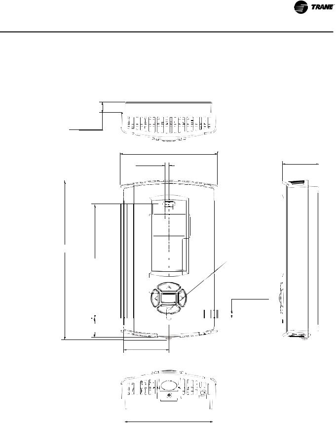
Dimensions
The following illustration provides specific dimension details. The dimensions are the same for all models.
0.31 in (8 mm)
2.9 in (73.5 cm)
1.08 in (27.5 mm)
0.12 in (3 mm)
4.68 in (118.9 mm)
3.39 in (86 mm) |
|
TYP R.07 in |
||
|
||||
|
(R1.80 mm) |
|||
|
|
|
||
|
|
|
0.24 in (6.00 mm) |
|
|
|
|
|
|
|
|
|
|
|
0.58 in (14.76 mm) 


1.34 in (34.14 mm)
2.62 in (66.5 mm)
BAS-SVX17B-EN |
5 |

Pre-Installation
This section provides the following pre-installation information:
•Location considerations
•Height requirements
•Mounting surfaces
•Recommended wire lengths
Location Considerations
Placement of the sensor is critical to proper operation. When selecting a location, avoid the following:
•Areas of direct sunlight
•Areas in the direct airstream of air diffusers
•Exterior walls and other walls that have a temperature differential between the two sides
•Areas that are close to heat sources such as sunlight, appliances, concealed pipes, chimneys, or other heat-generating equipment
•Drafty areas
•Dead spots behind doors, projection screens, or corners
•Walls that are subject to high vibration
•Areas with high humidity
•High traffic areas (to reduce accidental damage or tampering)
Height Requirements
It is recommended that you mount the back plate a maximum distance of 54 inches above the floor. If a parallel approach by a person in a wheelchair is required, reduce the maximum height to 48 inches.
Note: Consult section 4.27.3 of the 2002 ADA (Americans with Disability Act) guideline, and local building codes, for further details regarding wheelchair requirements.
Mounting Surfaces
Using the hardware provided, mount the back plate to a flat surface such as sheetrock or plaster, or an electrical junction box. The sensor must be mounted plumb for accurate temperature control and to ensure proper air movement through the sensor.
•If mounting onto sheetrock or plaster, use the plastic threaded anchors (pre-drilling holes is not usually necessary) and the two M3.5 x 20 mm mounting screws.
•For mounting onto an electrical junction box, use the two 6-32 x 3/4 in. screws.
•If you are replacing a horizontally mounted sensor and need to cover an opening in the wall, use the adapter kit (p/n BAYMTPL103A).
6 |
BAS-SVX17B-EN |

Pre-Installation
Wire Length
Maximum recommended wire lengths for the sensor are given in Table 1:
Table 1. Recommended wire lengths
|
|
|
Maximum recommended wire length from unit |
|
Wire size |
|
controller to sensor |
|
|
|
|
|
|
|
AWG |
|
mm2 |
Meters |
Feet |
22 |
|
0.33 |
0–46 |
0–150 |
|
|
|
|
|
20 |
|
0.50 |
47–73 |
151–240 |
|
|
|
|
|
18 |
|
0.75 |
74–117 |
241–385 |
|
|
|
|
|
16 |
|
1.30 |
118–185 |
386–610 |
|
|
|
|
|
14 |
|
2.00 |
186–296 |
611–970 |
|
|
|
|
|
Note: The total resistance of these low voltage wires must not exceed 2.5 Ω/conductor. Any resistance greater than 2.5 Ω may cause the control to malfunction due to an excessive voltage drop.
BAS-SVX17B-EN |
7 |
Installation
This section provides step-by-step installation instructions. Read through the pre-installation information before proceeding with the installation.
Note: Before installing the sensor, ensure that:
•A wire access hole is available at the sensor location
•The wires are accessible through the hole
•The wires are attached to the appropriate unit controller
•There is continuity between the sensor location and the unit controller
•The wires are accurately labeled or identified by color
Mounting the Back Plate
WARNING
Hazardous voltage!
Disconnect all electric power, including remote disconnects before servicing. Follow proper lockout/tagout procedures to ensure the power cannot be inadvertently energized. Failure to disconnect power before servicing could result in death or serious injury.
NOTICE
Equipment damage!
Applying excessive voltage to the sensor will permanently damage it.
Note: Refer to the illustration below when installing the sensor.
1.Shut off power to the unit controller.
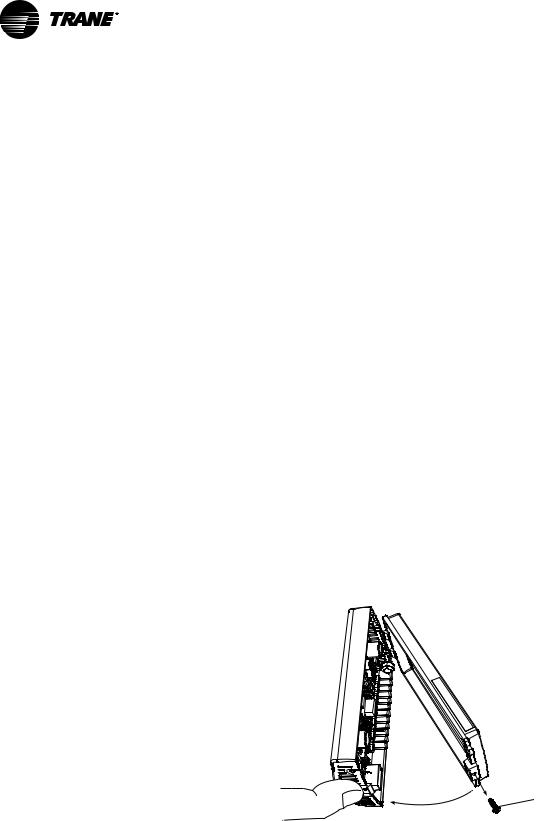
2.Remove the cover by firmly pressing the thumb tab at the bottom of the cover and pulling the cover away from the back plate.
Note: If present, remove the security screw before removing the cover.
 Security screw
3.Determine the number of wires required by referring to Table 2, p. 10.
4.Feed the wires through the opening in the back plate.
5.Hold the back plate against the mounting surface and mark the screw locations.
6.Secure the back plate to the mounting surface using the included hardware.
8 |
BAS-SVX17B-EN |

Installation
Wiring the Sensor
WARNING
Hazardous voltage!
Disconnect all electric power, including remote disconnects before servicing. Follow proper lockout/tagout procedures to ensure the power cannot be inadvertently energized. Failure to disconnect power before servicing could result in death or serious injury.
NOTICE
Equipment damage!
Applying excessive voltage to the sensor will permanently damage it.
To wire the sensor to the unit controller (see guidelines for wire sizes and lengths in Table 1, p. 7.):
1.Ensure that the wires are connected to the appropriate terminals at the unit controller.
2.Connect the wires to the terminal block (included in the hardware package with the sensor). See Table 2, p. 10 to determine where to terminate wires in the terminal block.
Note: The numbers on the terminal block correspond to the numbers on the terminals of the unit controllers most frequently used with the sensor.
3.Attach the terminal block to the pins on the circuit board inside the sensor cover (Figure 1).
Figure 1. Attaching the terminal block to the pins on the circuit board
4.Push the excess wire into the wall cavity and plug it with nonflammable insulation to prevent drafts from affecting the sensor.
Important: Do not coil excess wire inside the back plate.
BAS-SVX17B-EN |
9 |
10 |
Table 2. Programmable zone sensor wiring diagram |
|
|
|
|
|
|
|
|
|||||||||
|
|
|
|
|
|
|
|
|
|
|
|
|
|
|
|
|
|
|
|
|
|
|
|
|
|
|
|
|
|
|
|
|
|
|
YC* TE* |
YC* TE* |
|
|
|
|
|
|
|
|
|
|
|
|
|
|
|
20–130 |
|
TC |
TC |
|
|
|
|
|
|
|
|
|
|
|
|
3–20 |
|
|
ton |
90–162 |
330–600 |
330–600 |
Commercial |
|
|
|
|
|
|
|
|
|
3–25 ton |
split |
|
|
packaged |
ton |
model |
model |
self- |
|
|
|
|
|
|
|
|
|
|
packaged rooftops |
system |
27.5–50 ton |
rooftops |
packaged |
number |
number |
contained |
||
|
|
|
|
|
|
|
|
|
|
|
units |
packaged rooftops |
|
rooftops |
10thdigit |
10thdigit |
(CSC) |
|
|
|
|
|
|
|
|
|
|
*CD/*CH/*SC/ |
|
|
|
S*HF/ |
|
= A+ L |
= M+ |
|
|
|
|
|
|
|
|
|
|
|
*HC |
TTA/TWA |
YC*/TC*/TE* |
W*HB |
S*HJ |
LTB1 |
RTRM J6 |
S**F, S**G |
||
|
|
|
|
|
|
|
|
|
UCP |
ReliaTel |
ReliaTel |
UCP |
ReliaTel |
|
|
UCP |
ReliaTel |
|
|
|
|
|
|
|
|
|
|
control |
Control |
Control |
control |
Control |
IntelliPak |
IntelliPak |
control |
Control |
|
|
Sensor |
|
|
LTB(1) |
J6 |
J6 |
LTB1(1) |
J6 |
1TB4 |
1TB4 |
LTB1(1) |
J6 |
IntelliPak |
|||||
|
REMOTE SENSOR INPUT(2) |
S2 |
|
|
|
|
|
Optional |
remote sensor |
|
|
|
||||||
|
REMOTE SENSOR INPUT(2) |
S1 |
|
|
|
|
|
Optional remote sensor |
|
|
|
|||||||
|
24 VAC INPUT(3) |
14 |
------- |
14(4) |
14 |
14 |
14 |
14 |
14 |
1 |
14 |
14 |
1TB11-4 |
|||||
|
COMMUNICATIONS(5) |
12 |
------- |
12 |
12 |
12 |
12 |
12 |
12 |
12 |
12 |
12 |
1TB8-12 |
|||||
|
COMMON(3) |
11 |
------- |
11 |
11 |
11 |
11 |
11 |
6 |
7 |
11 |
11 |
1TB8-11 |
|||||
|
SERVICE STATUS (UCM INPUT) |
10 |
------- |
10 |
10 |
10 |
10 |
10 |
10 |
11 |
10 |
10 |
1TB8-10 |
|||||
|
|
|
|
|
|
|
|
|
|
|
|
|
|
|
|
|
|
|
|
SYSTEM STATUS (ON/OFF INPUT) |
9 |
------- |
9 |
9 |
9 |
9 |
9 |
9 |
10 |
9 |
9 |
1TB8-9 |
|||||
|
|
|
|
|
|
|
|
|
|
|
|
|
|
|
|
|
|
|
|
COOL STATUS |
8 |
------- |
8 |
8 |
8 |
8 |
8 |
8 |
9 |
8 |
8 |
1TB8-8 |
|||||
|
(UCM INPUT) |
|||||||||||||||||
|
|
|
|
|
|
|
|
|
|
|
|
|
||||||
|
|
|
|
|
|
|
|
|
|
|
|
|
|
|
|
|
|
|
|
HEAT STATUS |
7 |
------- |
7 |
7 |
7 |
7 |
7 |
7 |
8 |
7 |
7 |
1TB8-7 |
|||||
|
(UCM INPUT) |
|||||||||||||||||
|
|
|
|
|
|
|
|
|
|
|
|
|
||||||
|
|
|
|
|
|
|
|
|
|
|
|
|
|
|
|
|
|
|
|
AUX RELAY (CLOSED— |
|
|
|
|
|
A3 |
|
|
|
|
|
|
|
|
|
|
|
|
|
|
|
|
|
|
|
|
|
|
|
|
|
|
|
|||
|
UNOCCUPIED) |
|
|
|
|
|
|
|
|
|
|
|
|
|
|
|
|
|
|
|
|
|
|
|
|
|
|
|
|
|
|
|
|
|
|
|
|
|
AUX RELAY (COMMON) |
|
|
|
|
|
A2 |
|
The auxiliary relay on the sensor is form C, rated for 1.25 A at 30 Vac. It is energized during occupied periods. |
|||||||||
|
|
|
|
|
|
|
||||||||||||
|
AUX RELAY (CLOSED— |
|
|
|
|
|
|
|
|
|
|
|
|
|
|
|
|
|
|
|
|
|
|
|
A1 |
|
|
|
|
|
|
|
|
|
|
|
|
|
|
|
|
|
|
|
|
|
|
|
|
|
|
|
|
|
||
|
OCCUPIED) |
|
|
|
|
|
|
|
|
|
|
|
|
|
|
|
|
|
|
|
|
|
|
|
|
|
|
|
|
|
|
|
|
|
|
|
|
|
|
|
|
|
|
|
|
|
|
|
|
|
|
|
|
|
|
|
(1)LTB and LTB1 refer to low-voltage terminal boards with numbers 1–20 and two test terminals.
(2)Connect an optional remote sensor (p/n BAYSENS017) to terminals S1 and S2. Connect the shield wire (drain wire) from the shielded cable to terminal 11. (3)Connect the 24 Vac power supply from the unit controller to terminals 11 and 14. (IntelliPak power supply voltage is 12–15 Vac.)
(4)Use terminal 15 on older 3–25 ton Voyager units with low-voltage terminal boards numbered 1–18 with two test terminals. (5)Data communication between the unit controller and the sensor is accomplished by a serial link connected at terminal 12.
EN-SVX17B-BAS
Installation
Loading...