


ZG 215N
MOUNTING INSTRUCTIONS
Compact control units
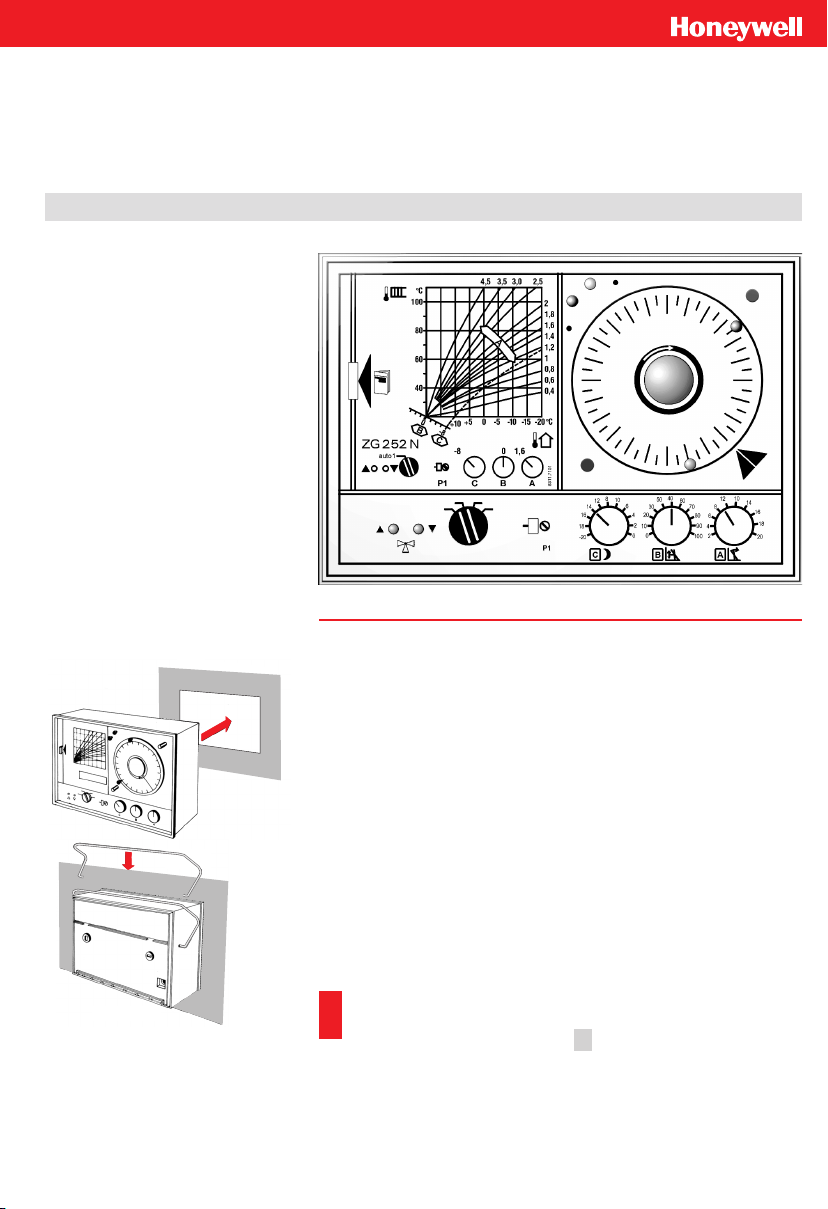
ZG 215N / 215 VN / 252 N
Ê
Ë
Mounting of the Control Unit
It can be mounted in any dry room, e. g. the boiler room. The device
can be mounted either in a cubicle door or on the wall.
Maximum permissible ambient temperature: 45 °C.
Door Mounting
Ê The casing cover isheldby a snap hinge closure.Press it inthe di
-
rection of the arrow on the left side and pull out.
Ë Insert the control unit in the dedicated door opening
(183 x 126 mm).
Ì Expand the retaining clips at the ends and insert in the relevant
holes. Fix into place the retaining clips by pressing down in the
fastening position.
Í Execute the electrical connection in the base (see the next page).
Then put on the base.
Important:
If the heating system is empty, the ZG 252N’s operating mode
selector is to be positioned on 2 . By doing so, the circulation
pump is deactivated and protected against dry-running.
ÊË
ÎÏ
ÌÍ
Ð
Ñ
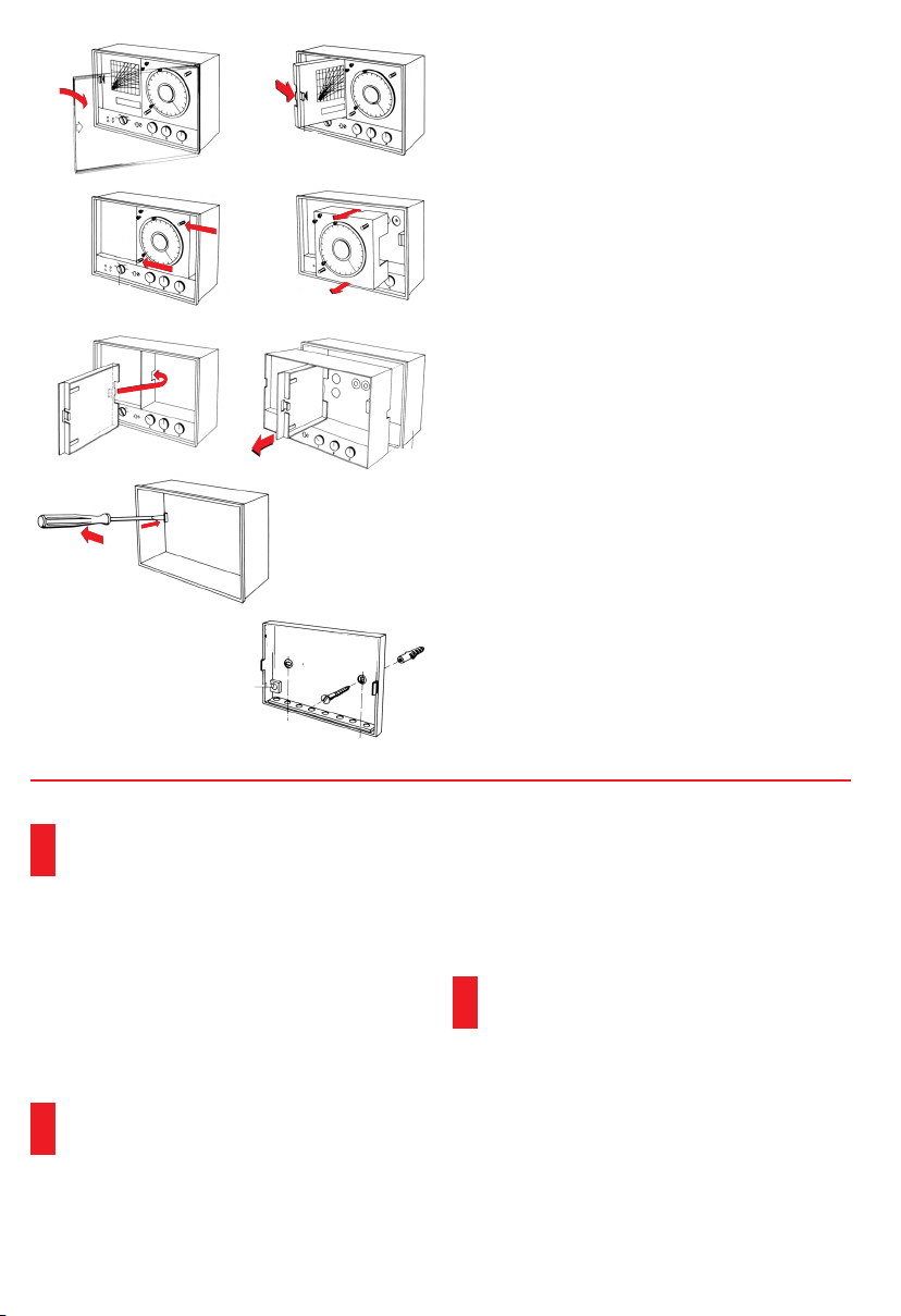
Wall mounting
Ê The casing cover is held by a snap hinge closure.
Press it in the direction of the arrow on the left
side and pull out.
Ë Hold the discharge compartment by the handle
and turn out to the right by exerting a light pres
-
sure. The instructions manual is kept here.
Ì Press the timer on bothpin inthe direction of the
arrow.
Í Pull out the timer.
Î Hang the slide of the instructions case in the
relevant recess of the insert.
Ï Pull the controller insert out of the casing with
the aid of the slide on the instructions case.
Ð Press the left lock pinto theleft witha screwdri
-
ver; by doing so, the case is freed from the devi
-
ce’s base.
Ñ Mount the device’s base with two 0.4 mm Æ
screws and dowels horizontally on the wall.
The assembly is to be carried out in the opposite
order.
Electrical Connections
The electrical connections are to be carried
out by a technician!
Cross sections
n
Left terminal strip (base):
230 V AC 1.5 mm²
(connection to the control unit, servomotor,
pump)
n
Right terminal strip (base):
18 V DC >= 0.75 mm²
(connection to the sensors and selectors)
The 18 V lines are to be laid separately from
the 230 V lines. Use shielded cablesin the pre
-
sence of intense HF disturbance fields!
Wiring
The single accessory parts are to be connected ac
-
cording to the wiring diagram on the back of the ca
-
sing of this device model. When using the ZG 252N
in low temperature heating systems (e.g. floor hea
-
ting) an additional thermostat is recommended to
provide separate over-temperature limitation. With
230 V/50 Hz the servomotor and circulation pump
require the jumper from terminal 5 to 6.
The local regulations on earthing and
resetting are to be followed carefully
when connecting the device.
Earlier temperature selector and sensor versions
without additional letters A (e. g. TW 20, RF 20,
TF 20, etc.) have the same electrical connections
and the same resistance values as the device
versions with with additional letter A.
Noise suppression
Our control units are all provided with noise sup
-
pression.
 Loading...