


 Loading...
WSK-24 Wireless Occupancy Solution
INSTALLATION INSTRUCTIONS
PRODUCT DESCRIPTION
The WSK-24 Wireless Occupancy Solution automatically controls HVAC equipment by determining when a room is occupied. The WSK-24 uses the combination of an occupancy sensor and a door switch to provide optimal control. The WSK-24 is packaged in a kit that includes the following components:
•One 24V dry contact receiver
•One wireless PIR (passive infrared receiver) occupancy sensor with mounting kit
•One wireless door sensor with mounting kit
•One wiring harness.
The receiver can be wired into any thermostat or controller that supports the connection of a remote setback device. The receiver communicates wirelessly to a PIR occupancy sensor, a door sensor, and an optional 2nd door/window sensor. After the receiver determines
that the room is unoccupied it closes a dry contact switch. After the thermostat or controller recognizes the contact closure, it places the thermostat in economy setback mode, which provides energy savings for when the room is unoccupied.
FEATURES
•Wireless system provides quick and easy installation
•Pre-configured door sensor and occupancy sensor
•Guest comfort is maintained by never turning off HVAC equipment when someone is in the room – even if they are sleeping
•Fuse protection
•Long battery life
•Low battery indication
•Receiver memory retained after power loss
•Optional sliding door/window sensor can be easily added
Contents |
|
Product Description .................................................... |
1 |
Features ..................................................................... |
1 |
Ordering Information .................................................. |
2 |
Specifications ............................................................. |
2 |
Installation .................................................................. |
3 |
Thermostat Configuration ................................. |
3 |
Wiring ................................................................ |
3 |
Setting the Delay on the Receiver .................... |
4 |
Mounting ........................................................... |
4 |
Battery Replacement ........................................ |
6 |
Operation ................................................................... |
6 |
Door (Zone 1) and PIR Occupancy Motion Sensor |
|
(Zone 2) ............................................................ |
6 |
Optional Sliding Door/Window Sensor (Zone 3) |
6 |
Sensor Discovery ....................................................... |
7 |
System Testing ........................................................... |
7 |
Front Door Sensor & PIR Sensor ..................... |
7 |
2nd Door Sensor ............................................... |
7 |
Limited Two-Year Warranty ........................................ |
8 |
Customer Assistance ................................................. |
8 |
62-0300ES-01
WSK-24 WIRELESS OCCUPANCY SOLUTION
ORDERING INFORMATION
When purchasing replacement and modernization products from your TRADELINE® wholesaler or distributor, refer to the TRADELINE® catalog or price sheets for complete ordering number. Orders can also be placed at http://customer.honeywell. com.
If you have additional questions, need further information, or would like to comment on our products or services, please write or phone:
1.Your local Honeywell Automation and Control Products sales office (check the white pages of your phone directory).
2.Honeywell Customer Care 1885 Douglas Drive North
Minneapolis, Minnesota 55422-4386 (763) 954-5720
3.In Canada–Honeywell Limited/Honeywell Limitée, 35 Dynamic Drive, Toronto, Ontario M1V 4Z9.
International sales and service offices are located in all principal cities of the world. Manufacturing is in Australia, Canada, Finland, France, Germany, Japan, Mexico, the Netherlands, Spain, Taiwan, United Kingdom, and U.S.A.
SPECIFICATIONS
Operating Temperature:
Receiver: -21 to 60°C (-5 to 140°F) Door Sensora: -20 to 60°C (-4 to 140°F) PIR Sensor: -20 to 40°C (-4 to 104°F)
Power Supply:
Receiver: 24 Vac/Vdc at 50/60 Hz; Standby power consumption 15 mA; Channel 1 relay output, N.O.
Door Sensora: Two CR2032 lithium batteries
PIR Sensor: Three AAA E92 1.5V alkaline batteries
Battery Life:
Door Sensora: Two years (under normal usage) PIR Sensor: One year (under normal usage)
Receiver Operating Frequency:
Receiver: 433.92 MHz
Door Sensora: 433.92 MHz
PIR Sensor: 433.92 MHz
Receiver Frequency Range:
•With antenna exposed:
•Open Range: 200 ft.
•Typical Range: 100 ft.
•With antenna coiled inside receiver:
•Open Range: 50 ft.
•Typical Range: 40 ft.
aand 50037735-001, the optional sliding door/window sensor
ORDERING INFORMATION
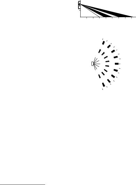
PIR Detection Pattern:
Length: 3 to 8 meters when mounted 2 meters above the floor (see Fig. 1)
Angle: 140 degrees (see Fig. 2)
M
2
1
1 |
2 C 3 |
4 B 5 |
6 |
7 A 8 |
M |
|
|
LENGTH 3 ~ 8 M |
|
|
M29142 |
Fig. 1. Side view of PIR detection pattern.
70°
60°
50°
|
40° |
|
30° |
|
20° |
|
10° |
|
0° |
|
10° |
|
20° |
|
30° |
|
40° |
|
50° |
|
60° |
70° |
M29143 |
Fig. 2. Top view of PIR detection pattern.
Dimensions:
Door Sensora: 1.4 x 2.3 x 0.6 in (35.8 x 57.6 x 15.2 mm)
Receiver: 3.6 x 3.4 x 1.2 in (91.4 x 86.4 x 30.5 mm) PIR Sensor: 2.8 x 3.9 x 1.1 in (71 x 100 x 28 mm)
Approvals: FCC Part 15 Class B
Accessories:
• 50037735-001: Optional Sliding Door/Window Sensor
Replacement Parts:
•50037737-001: Wireless Receiver
•50037736-001: Wireless PIR Occupancy Sensor
62-0300ES—01 |
2 |
INSTALLATION
INSTALLATION
When Installing this Product…
1.Read these instructions carefully. Failure to follow them could damage the product or cause a hazardous condition.
2.Check the ratings given in the instructions and on the product to make sure the product is suitable for your application.
3.Installer must be a trained and experienced service technician.
 WARNING
Risk of electrical shock.
Can cause severe injury, property damage or death.
Disconnect power supply before installation and before servicing.
IMPORTANT
The thermostat may be a line voltage powered device. All wiring must comply with national and local electrical codes, ordinances and regulations.
The WSK-24 must be powered by an Approved 24 Vac, Class 2, NEMA rated transformer.
Thermostat Configuration
Refer to the thermostat’s installation instructions for programming, mounting, and wiring the thermostat.
The receiver has a normally open dry contact relay. Therefore, the thermostat should be set so that the relay on the thermostat is normally closed.
Use Table 2 or Table 1 to determine the desired Installer Codes for the thermostat being used with the WSK-24.
Table 1. MultiPRO™ Installer Setup Codes.
IS |
Code |
Option |
Option Description |
Code |
Description |
Value |
|
0160 |
Schedule Options |
0 |
Non-Programmable |
0340 |
Remote Temp |
5 |
Remote Setback |
(Non- |
Sensor/Remote |
|
|
program |
Setback/ |
|
|
mable) |
Changeover |
|
|
|
Input |
|
|
0341 |
Delay for Remote |
0 |
No Delay |
|
Setback |
|
|
|
2 |
Two Minute Delay |
|
|
|
||
|
|
|
|
0342 |
Override Option |
0 |
No Override during |
|
|
|
unoccupied |
|
|
1 |
Override during |
|
|
|
unoccupied |
0343 |
Unoccupied |
50-65 |
Range is 50 to 65°F |
|
Heating Setpoint |
|
(10 to 18°C) |
0346 |
Unoccupied |
75-90 |
Range is 75 to 90°F |
|
Cooling Setpoint |
|
(24 to 30°C) |
WSK-24 WIRELESS OCCUPANCY SOLUTION
Table 2. SuitePRO™ Installer Setup (IS) Codes.
IS |
Code |
Option |
Option Description |
Code |
Description |
Value |
|
|
|
|
Hotel Card enabled N.C. with |
|
|
|
1 second software delay |
|
|
2 |
going from UnOccupied to |
|
|
Occupied; |
|
|
|
|
|
|
|
|
2 minute delay going from |
19 |
Remote |
|
Occupied to UnOccupied. |
Setback |
|
Hotel Card enabled N.C. with |
|
|
|
||
|
|
|
1 second software delay |
|
|
4 |
going from UnOccupied to |
|
|
Occupied; |
|
|
|
|
|
|
|
|
30 minute delay going from |
|
|
|
Occupied to UnOccupied. |
20 |
Remote |
50-70 |
Range is 50 to 70°F |
|
Setback for |
|
(10 to 21°C) |
|
Heating |
|
|
21 |
Remote |
72-90 |
Range is 72 to 90°F |
|
Setback for |
|
(22 to 32°C) |
|
Cooling |
|
|
Wiring
Prepare Thermostat for Receiver Wiring
Turn off the thermostat and remove the power source from the thermostat.
 WARNING
Risk of electrical shock.
Can cause severe injury, property damage or death.
Disconnect power supply before servicing.
 CAUTION
Equipment Damage Hazard.
Improper removal can damage the thermostat.
Carefully follow the thermostat removal directions.
Receiver and Thermostat Terminal Wiring
Table 3. Wiring Designations
Receiver |
Typical |
|
Harness |
Thermostat |
|
Wire |
Terminals |
Connection |
Red |
R |
24 Vac Power |
|
|
|
White |
C |
24 Vac Common |
|
|
|
White/ |
Sc |
Dry Contact; Normally |
Brown |
|
Open |
Brown |
Sb |
Dry Contact; Common |
|
|
|
3 |
62-0300ES—01 |
WSK-24 WIRELESS OCCUPANCY SOLUTION |
INSTALLATION |
TO THERMOSTAT
 WIRING
HARNESS
 RECEIVER
1.WIRE RED AND WHITE WIRES TO 24 VAC POWER AND COMMON.
2.WIRE WHITE/BROWN AND BROWN WIRES TO DRY CONTACT TERMINALS ON THERMOSTAT.
 ANTENNA
M29150
Fig. 3. Receiver and wiring harness.
Using Table 3 on page 3 and Fig. 3, wire the harness to the thermostat and connect the harness to the receiver.
1.Wire the red and white power leads on the wiring harness into the power terminals on the thermostat.
2.Wire the white/brown and brown dry contact leads on the wiring harness into the remote setback terminals on the thermostat.
3.Plug the wiring harness into the receiver. The harness is keyed and fits only one way.
4.Supply power to the thermostat.
5.The LED on the receiver flashes twice to show it has power.
6.Continue with “Setting the Delay on the Receiver”.
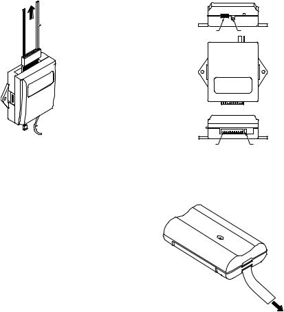
Setting the Delay on the Receiver
Refer to Fig. 4 and position the jumper to the desired delay option:
Position the jumper near the pushbutton:
—Front Door - 3 minute delay
—2nd optional door - 1 minute delay
Position the jumper away from the pushbutton (default position):
—Front Door - 15 second delay
—2nd optional door - 1 minute delay
The receiver delay and the delay that is programmed in the thermostat will be combined to provide an overall delay.
Mounting
Mounting the Receiver
The receiver can be mounted behind the thermostat in the wall, inside the fan coil unit, or mounted on the wall.
Mounting screws or double-sided adhesive tape can be used to mount the receiver.
TOP END VIEW
JUMPER PUSHBUTTON
BOTTOM END VIEW |
|
WIRING |
LED |
HARNESS |
|
CONNECTOR |
M29151 |
Fig. 4. Receiver components.
Mounting the Door Sensor
1. Remove battery tab before installation. See Fig. 5.
PULL OUT
BEFORE USE
M29152
Fig. 5. Battery tab removal.
2.Remove the plastic mounting bracket from the door sensor housing.
3.Place the mounting bracket for the door sensor high on the frame of the front door. Secure the bracket to the door frame by using the two screws or adhesive tape provided. See Fig. 6 on page 5.
62-0300ES—01 |
4 |

INSTALLATION
SCREWS TO
HOLD BRACKET
MOUNTING
BRACKET
TAB TO RELEASE
DOOR SENSOR
ADHESIVE
TAPE
M29153
Fig. 6. Door sensor bracket mounting.
4.Make sure the notched side of the door sensor is pointing in the direction that you will mount the magnet. See Fig. 7 and Fig. 8.
TAB
NOTCHES
WSK-24 WIRELESS OCCUPANCY SOLUTION
8.Secure the magnet to the door by using the two screws or adhesive tape provided. An optional spacer is provided, as well. See Fig. 9.
 SCREWS TO
MAGNET OR
SPACER
OPTIONAL
SPACER
 ADHESIVE
TAPE
M29156
Fig. 9. Door magnet mounting options.
9.Open and close the door to ensure that there is no interference.
CHECK THE DOOR SENSOR FUNCTION
1.Open the door and verify that the LED on the door sensor flashes three times when the contact is opened.
2.Close the door and verify that the LED on the door sensor flashes another three times.
TAB
NOTCHES M29154
Fig. 7. Door sensor tab notches.
5.Snap the sensor in place.
6.Align one end of the magnet with the notched side of the door sensor housing.
7.Mount the magnet a maximum of 3/4 in. (19 mm) from the door sensor, as illustrated in Fig. 8.
TAB
NOTCHES
MUST FACE
THE MAGNET
1
1 MAXIMUM DISTANCE BETWEEN SENSOR AND
MAGNET 3/4 (19). |
M29155 |
|
Fig. 8. Maximum distance between door sensor and magnet.
Mounting the PIR Occupancy Motion Sensor
COVER
SCREWS
TO HOLD
SENSOR
PLASTIC
CONICAL
ANCHORS
|
|
PIR BACK |
|
|
PLATE |
|
ADHESIVE |
SCREW TO |
|
TAPE |
RELEASE |
SCREWS |
MOUNTING |
COVER |
TO FIX THE BRACKET |
|
|
BRACKET |
|
M29157 |
Fig. 10. PIR occupancy motion sensor mounting options.
1.Take off the cover by removing the cover release screw on the bottom of the PIR back plate.
2.Power the PIR sensor by inserting the three AAA batteries provided. See Fig. 12 for proper battery orientation.
3.Secure the PIR sensor to the wall using one of the following three options
5 |
62-0300ES—01 |
Loading...