


UDC3500
01/06 Kit Instruction 51-52-33-153 1
UDC3500 Universal Digital Controller
Printed Wiring Board Replacements
Instruction 51-52-33-153
• Kit contents
This kit contains one of the following replacement Printed Wiring Boards:
• UDC3500 MCU/Input Board – Part No. 51452828-502
• UDC3500 Power 90-264 Vac Board – Part No. 51452831-501
• UDC3500 Power 24 Vac/dc Board – Part No. 50006376-501
• UDC3500 Display/Keyboard – Part No. 51452845-501
• UDC3500 Dual Relay Board – Part No. 51452807-501
• UDC3500 Optional Input Board – Part No. 51452825-501
• UDC3500 Third Current Output Board – Part No. 51452834-501
• UDC3500 Aux Out/Digital Inputs/RS-485 – Part No. 51452837-502
• UDC3500 Digital Inputs/Ethernet Board – Part No. 51452840-501
• UDC3500 Optional Relay Board – Part No. 51452843-501
Equipment needed
• Small flat-bladed screwdriver
• Small pliers
Procedures
The procedure tables that follow list the steps required to replace the old
Printed Wiring Board in your controller with the one supplied in this kit.
Continued on next page
2 Kit Instruction 51-52-33-153 01/06
Replacement Instruction, Continued
Chassis removal
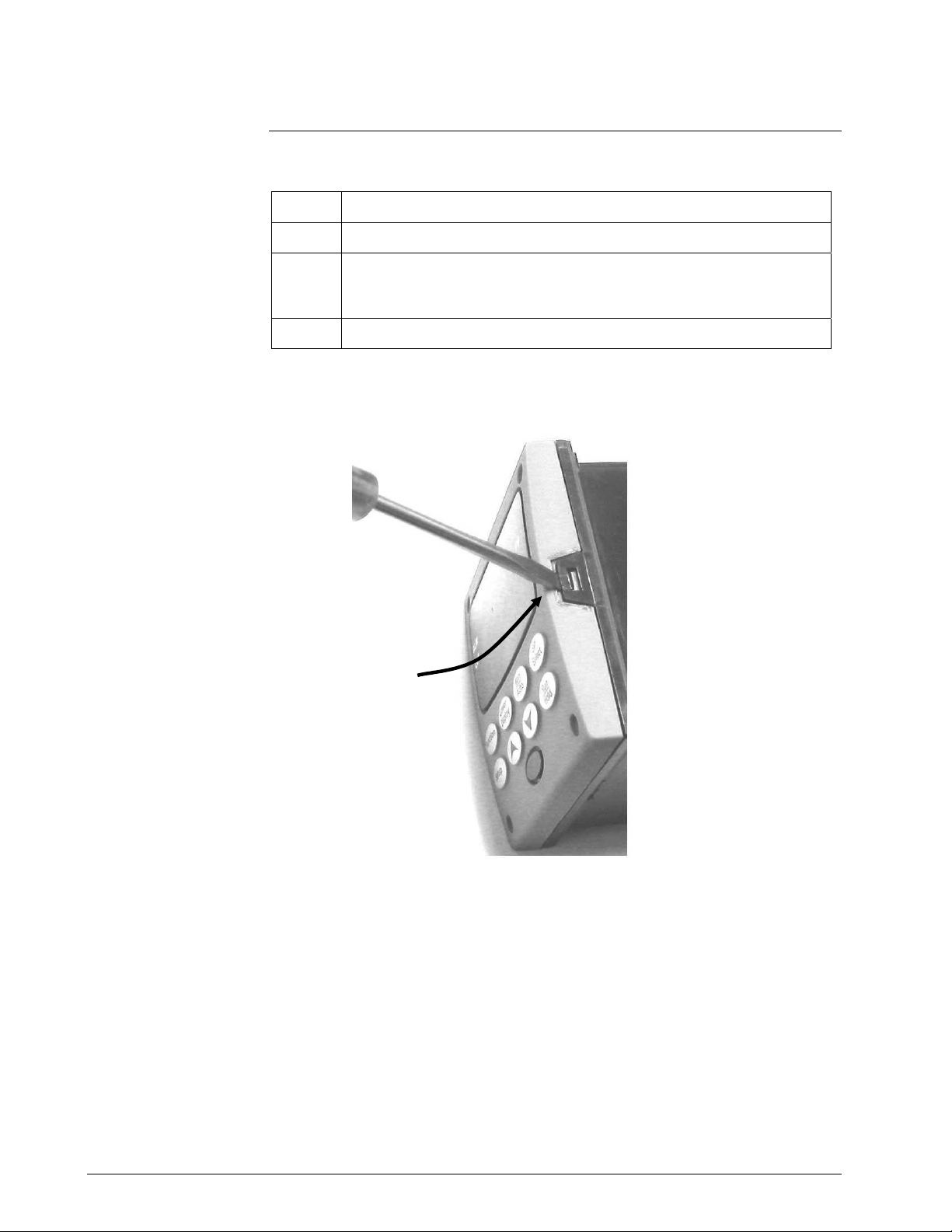
Table 1 How to Remove the Chassis
Step Action
1
Remove any screws in the front face.
2
Insert a flat-bladed screwdriver into the tabs of the case as shown in
Figure 1 and pry chassis forward slightly until the chassis connectors
separate from the back of the case.
3
Grasp the bezel and pull the chassis out of the case.
Figure 1 Chassis Removal
Using a thin screwdriver, gently twist the screwdriver to pry the side tabs from the front
face. Pry just enough to release it, otherwise you’ll bend or break the tab. If you break or
bend the tab and can’t reattach the front snugly, you’ll need to reattach the front using the 4
NEMA4 screws provided.
Continued on next page
Insert thin screwdriver under
tabs and twist slightly and
gently to disengage front
01/06 Kit Instruction 51-52-33-153 3
Replacement Instruction, Continued
Printed wiring board
removal
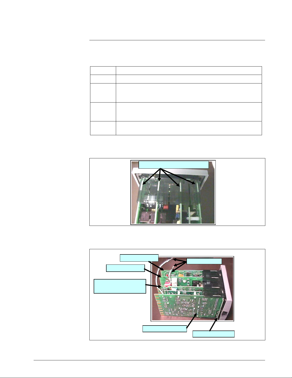
Table 2 How to Remove the Printed Wiring Boards from the Chassis
Step Action
1
Remove the chassis from the case as shown in Figure 1.
2
Separate the chassis frame at the release points shown in Figure 2
and wiggle each printed wiring board out of its socket on the
display/keyboard assembly. Pull all boards out of the chassis.
3
Remove the wire connectors from plug WG1 on Power/Output
Board. Slide a small screwdriver under the connectors and lift the
release.
4
Lay the printed wiring boards flat on a static-free surface. Use
Figures 3 through 6 to locate the board being replaced.
Figure 2 Removing the Printed Wiring Boards
Printed wiring board
identification
Figure 3 Major Printed Wiring Board Identification
Continued on next page
Release points (top and bottom)
Power / Out
p
ut Bd.
Auxiliary output / Digital
Inputs / Communication Bd.
MCU / Input Board
O
p
tional Rela
y
s Bd.
WG1 and Wires
Display / Keyboard
 Loading...