Honeywell TH8321U, TH8110U, TH8320U User Manual

Installation
Guide
VisionPRO® TH8000 Series
Touch-screen Programmable Thermostat
This manual covers the following models
•TH8110U: For 1 Heat/1 Cool systems
•TH8320U: For up to 3 Heat/2 Cool systems
•TH8321U: For up to 3 Heat/2 Cool systems with dehumidification
(Pull thermostat from wallplate and turn over to find model number)
System Types
•Gas, oil, or electric heat with air conditioning
•Warm air, hot water, highefficiency furnaces, heat pumps, steam, gravity
•Heat only — two-wire systems, power to open and close zone valves (Series 20), and normally open zone valves
•Heat only with fan
•Cool only
•750 mV heating systems
This thermostat contains a Lithium battery which may contain Perchlorate material.
Perchlorate Material—special handling may apply, See www.dtsc.ca.gov/hazardouswaste/perchlorate
Need Help?
For assistance with this product please visit http://customer.honeywell.com or call Honeywell Customer Care toll-free at 1-800-468-1502
® U.S. Registered Trademark. |
|
Copyright © 2012 Honeywell International Inc. |
|
All rights reserved. |
69-2693-01 |
|

Installation Guide
Wallplate installation
1.Separate wallplate from thermostat.
2.Mount wallplate as shown below.
Grasp top and bottom of wallplate and pull to remove from thermostat.
Drill 3/16” holes for drywall.
Drill 7/32” holes for plaster.
|
MCR29480 |
Wire hole |
Mounting screws |
Wall anchors
ENGLISH
MCR29481
Must be installed by a trained, experienced technician
•Read these instructions carefully. Failure to follow these instructions can damage the product or cause a hazardous condition.
CAUTION: ELECTRICAL HAZARD
Can cause electrical shock or equipment damage. Disconnect power before beginning installation.
MERCURY NOTICE
If this product is replacing a control that contains mercury in a sealed tube, do not place the old control in the trash. Contact your local waste management authority for instructions regarding recycling and proper disposal.
69-2693—01 |
2 |

VisionPROTM TH8000 Series
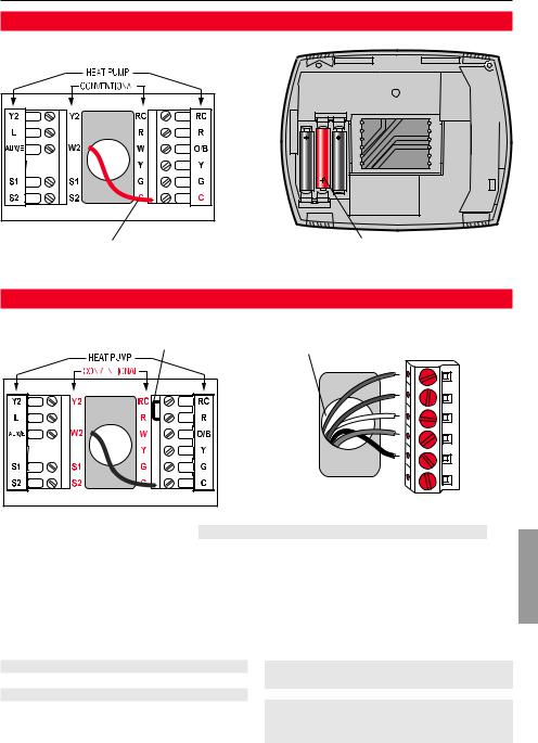
Power options
NOT |
USED |
For 24VAC primary power, connect common side of transformer to “C” terminal.
MCR29482
Insert supplied batteries for primary or backup power.
Wiring
Remove factory-installed jumper |
Push excess wire back into the wall opening. Plug |
only for two-transformer systems. |
wall opening with non-flammable insulation. |
NOT |
USED |
MCR29483 |
Terminal Designations Shaded areas below apply only to TH8320/TH8321. |
Conventional Terminal Letters:
RHeating power. Connect to secondary side of heating system transformer.
Rc Cooling power. Connect to secondary side of cooling system transformer.
CCommon wire from secondary side of cooling transformer (if 2 transformers).
W 1st stage heat relay. W2 2nd stage heat relay.
Y 1st stage compressor contactor. Y2 2nd stage compressor contactor.
G Fan relay.
S1 Optional outdoor or remote sensor.
S2 Optional outdoor or remote sensor.
Heat Pump Terminal Letters:
RHeating power. Connect to secondary side of heating system transformer.
Rc Cooling power. Connect to secondary side of cooling system transformer.
CCommon wire from secondary side of cooling system transformer.
Y 1st stage compressor contactor. Y2 2nd stage compressor contactor.
Aux/E Auxiliary/Emergency heat relay. G Fan relay.
LHeat pump reset (powered continuously when System is set to Em Heat; system monitor when set to Heat, Cool or Off).
O/B Changeover valve for heat pumps. S1 Optional outdoor or remote sensor. S2 Optional outdoor or remote sensor.
ENGLISH
3 |
69-2693—01 |

Installation Guide
Wiring
ENGLISH
Wiring guide—conventional systems
Shaded areas below apply only to TH8320/TH8321. |
|
|
|
|||
1H/1C System (1 transformer) |
1H/1C System (2 transformers) |
|||||
|
Rc |
Power [1] |
|
|
Rc |
Power (cooling transformer) [1, 2] |
|
R |
[R+Rc joined by jumper] |
|
|
R |
Power (heating transformer) [1, 2] |
|
W |
Heat relay |
|
|
W |
Heat relay |
|
Y |
Compressor contactor |
|
|
Y |
Compressor contactor |
|
G |
Fan relay |
|
|
G |
Fan relay |
|
C |
24VAC common [3] |
|
|
C |
24VAC common [3, 4] |
|
S1 |
Optional outdoor/remote sensor |
|
|
S1 |
Optional outdoor/remote sensor |
|
S2 |
Optional outdoor/remote sensor |
|
|
S2 |
Optional outdoor/remote sensor |
Heat Only System |
Heat Only System With Fan |
|||||||
|
Rc |
Power [1] |
|
|
Rc |
Power [1] |
|
|
|
R |
[R+Rc joined by jumper] |
|
|
R |
[R+Rc joined by jumper] |
|
|
|
W |
Heat relay |
|
|
W |
Heat relay |
|
|
|
C |
24VAC common [3] |
|
|
G |
Fan relay |
|
|
|
S1 |
Optional outdoor/remote sensor |
|
|
C |
24VAC common [3] |
|
|
|
S2 |
Optional outdoor/remote sensor |
|
|
S1 |
Optional outdoor/remote sensor |
|
|
Heat Only System (Series 20) |
|
S2 |
Optional outdoor/remote sensor |
|
||||
Cool Only System |
||||||||
|
Rc |
[R+Rc joined by jumper] |
|
|||||
|
R |
Series 20 valve terminal “R” [1] |
|
|
Rc |
Power [1] |
|
|
|
W |
Series 20 valve terminal “B” |
|
|
R |
[R+Rc joined by jumper] |
|
|
|
Y |
Series 20 valve terminal “W” |
|
|
Y |
Compressor contactor |
|
|
|
C |
24VAC common [3] |
|
|
G |
Fan relay |
|
|
|
S1 |
Optional outdoor/remote sensor |
|
|
C |
24VAC common [3] |
|
|
|
S2 |
Optional outdoor/remote sensor |
|
|
S1 |
Optional outdoor/remote sensor |
|
|
|
|
|
|
|
S2 |
Optional outdoor/remote sensor |
||
2H/2C System (1 transformer) |
|
|||||||
|
|
|
|
|
||||
|
Y2 |
Cool relay 2 |
|
2H/2C System (2 transformers) |
||||
|
W2 |
Heat relay 2 |
|
|
Y2 |
Cool relay 2 |
|
|
|
Rc |
Power [1] |
|
|
W2 |
Heat relay 2 |
|
|
|
R |
[R+Rc joined by jumper] |
|
|
Rc |
Power (cooling transformer) [1, 2] |
|
|
|
W |
Heat relay 1 |
|
|
R |
Power (heating transformer) [1, 2] |
|
|
|
Y |
Cool relay 1 |
|
|
W |
Heat relay 1 |
|
|
|
G |
Fan relay |
|
|
Y |
Cool relay 1 |
|
|
|
C |
24VAC common [3] |
|
|
G |
Fan relay |
|
|
|
S1 |
Optional outdoor/remote sensor |
|
|
C |
24VAC common [3, 4] |
|
|
|
S2 |
Optional outdoor/remote sensor |
|
|
S1 |
Optional outdoor/remote sensor |
|
|
|
|
|
|
|
S2 |
Optional outdoor/remote sensor |
||
|
|
|
|
|
|
|
|
|
See [notes] below
[1]Power supply. Provide disconnect means and overload protection as required.
[2]Remove jumper for 2-transformer systems.
[3]Optional 24VAC common connection.
[4]Common connection must come from cooling transformer.
69-2693—01 |
4 |
 Loading...