


TH8321WF
Reference to key features
* Password is the date code.
Wi-Fi VisionPRO® 8000
Installation Guide
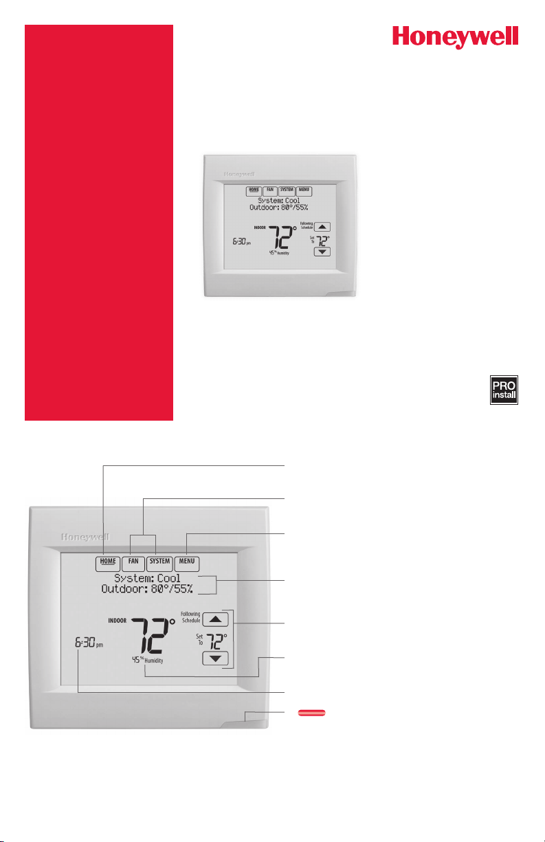
Current display. Underlined label
signifies the current display.
Mode control buttons. Use to change
settings for Fan or System Heat/Cool.
Menu. Select options to: set schedules,
view equipment status, change IAQ
settings, access installer options*, etc.
Current status. Shows system mode
(heat/cool), outdoor temperature and
humidity.
Current schedule. Shows desired
temperature and schedule status.
Indoor conditions. Shows indoor
temperature and humidity.
Current Time.
Alert Light. On when alert
message is active or system is set to
Em Heat.
1-855-733-5465
yourhome.honeywell.com
Honeywell
Golden
TH8321WF1001
M35343A
NO MERCURY
ATTENTION: MERCURY RECYCLING NOTICE
This product does not contain mercury. However, this
product may replace a product that contains mercury.
Hg
Mercury and products containing mercury should not be
discarded in household trash.
For more information on how and where to properly recycle
a thermostat containing mercury in the United States,
please refer to the Thermostat Recycling Corporation at
www.thermostat-recycle.org.
For mercury thermostat recycling in Canada, please refer
to Switch the Stat at
www.switchthestat.ca
Getting started
Follow these basic steps to install this thermostat,
set installer options, and connect to the Wi-Fi
network.
NOTE: For the product data sheet, please go to
forwardthinking.honeywell.com
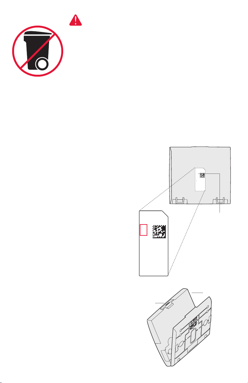
Installing the thermostat
1 Separate wallplate from thermostat.
Press button on top and pull to remove
the wallplate.
RoHs Compliant
Conformité RoHs
Assembled in Mexico
Assemblé au Mexique
1524
1
Button
Thermostat (back view)
RoHs Compliant
Conformité RoHs
Assembled in Mexico
Assemblé au Mexique
1524
1
TH8321WF1001
Residential/Résidentiel
1-800-468-1502
http://yourhome.honeywell.com
Commercial/Commerciale
1-888-245-1051
http://customer.honeywell.com
Honeywell, Golden Valley, MN 55422
Password
(Date Code)
Valley, MN 55422
Thermostat
2
Wallplate
(back view)
CONVENTIONAL
CONVENTIONAL
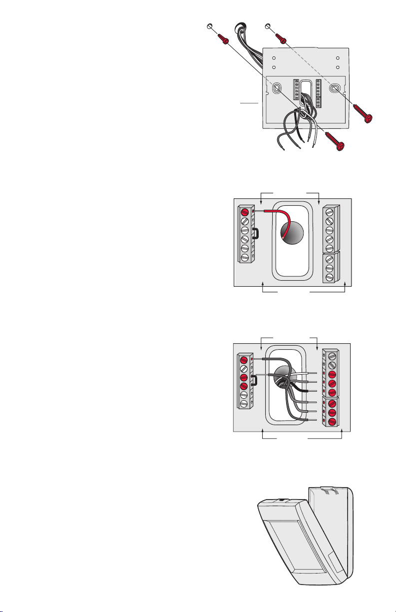
2 Mount wallplate as shown.
Mount new wallplate using screws
and anchors included with the
thermostat.
Drill 3/16-in holes for drywall.
Drill 7/32-in holes for plaster.
3 Connect power.
24VAC power is required. Connect
common side of transformer to C
terminal.
Wallplate
S1
C
K
R
R
U1
U1
U2
U2
C
K
RC
R
U1
U1
U2
U2
HEAT PUMP
S1
S1
S1
C
W
O/B
Y
Y
G
G
AUX
W2
-E
Y2
Y2
L/A
A
S1
S1
S1
S1
O/B
W
Y
Y
G
G
AUX
W2
-E
Y2
Y2
A
L/A
4 Wire the thermostat.
Refer to the table and wiring
diagrams on the next page.
a Turn on 24VAC NOW.
24VAC (C wire) is required.
5 Mount thermostat on wallplate.
Align thermostat at bottom and
snap into place as shown.
3
C
K
RC
R
U1
U1
U2
U2
Thermostat
HEAT PUMP
S1
S1
S1
S1
O/B
W
Y
Y
G
G
AUX
W2
-E
Y2
Y2
A
L/A
Wallplate
Terminal Designations
SYSTEM
1
1
SYSTEM
TRANSFORMER
Conventional System Heat Pump
Terminal Description Terminal Description
Common wire from secondary side of
C
cooling transformer (if 2 transformers).
Rc* Cooling power. Rc Cooling power.
R* Heating power. R Heating power.
W Heat Stage 1 O/B Changeover valve for heat pumps.
W2 Heat Stage 2 AUX-E Backup Heat/Emergency Heat
Y Compressor Stage 1 Y Compressor Stage 1
Y2 Compressor Stage 2 Y2 Compressor Stage 2
G Fan Relay G Fan Relay
Connect to Economizer Module or
A
Lighting Panel (TOD).
U1 / U1
S1 / S1
Universal relay for humidification,
dehumidification, ventilation, or a stage of
heating/cooling.
Universal input for a wired indoor, outdoor
or discharge sensor.
U1 / U1
S1 / S1
K** Connect to K on Wire Saver module. K** Connect to K on Wire Saver module.
Common wire from secondary side of
C
cooling transformer.
Connect to Compressor Monitor, Zone
L/A
Panel, Economizer Module or Lighting
Panel (TOD).
Universal relay for humidification,
dehumidification, ventilation, or a stage of
heating/cooling.
Universal input for a wired indoor, outdoor
or discharge sensor.
* Remove factory installed jumper for two transformer systems.
** The THP9045A1023 Wire Saver module is used on heat/cool systems when you only have four wires at the thermostat and you
need a fifth wire for a common wire. Use the K terminal in place of the Y and G terminals on conventional or heat pump systems to
provide control of the fan and the compressor through a single wire—the unused wire then becomes your common wire. See THP9045
instructions for more information.
TRANSFORMER
C
THERMOSTAT
C
K
R
C
R
U1
U1
OR
POWERED
HUMIDIFIER,
DEHUMIDIFIER
OR VENTILATOR
THERMOSTAT
C
K
C
R
R
1
U1
U1
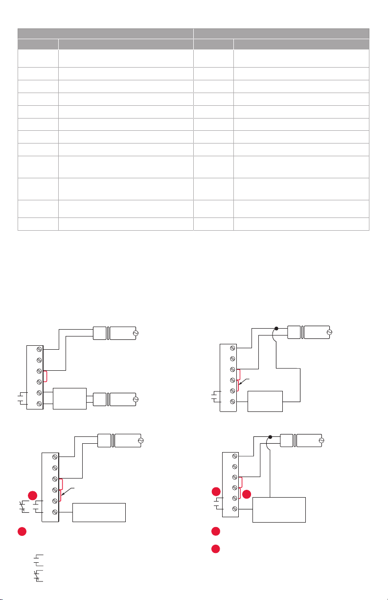
Wire the thermostat universal relay to the low speed fan
for dehumidication control at the equipment. The
thermostat relay can be set to normally open or
normally closed in the thermostat installer setup.
R
FIELD INSTALL JUMPER
BETWEEN R AND U1
DEHUMIDIFICATION
WITH LOW SPEED FAN
24
VAC
HUM, DEHUM OR
TRANSFORMER
24
VAC
C
24
VAC
R
VENT
120
VAC
120
VAC
120
VAC
Normally open, dry contacts
Normally closed, dry contacts
NON-POWERED HUMIDIFIER, DEHUMIDIFIER OR VENTILATORPOWERED HUMIDIFIER, DEHUMIDIFIER OR VENTILATOR
THERMOSTAT
C
K
R
C
FIELD INSTALL JUMPER
R
BETWEEN R AND U1
U1
NON-POWERED
U1
CONNECTING A HEAT OR COOL STAGE TO U1DEHUMIDIFICATION WITH LOW SPEED FAN
THERMOSTAT
1
2
HUMIDIFIER,
DEHUMIDIFIER
OR VENTILATOR
C
K
R
C
R
2
U1
U1
U1 terminals are normally open dry contacts when set
up for a stage of heating or cooling.
You must install a eld jumper if the stage of heating
or cooling is powered by system transformer. Do NOT
install a eld jumper if the stage of heating has its own
transformer.
HEAT STAGE 3, COOL
STAGE 3, BACKUP HEAT
STAGE 2 FOR HEAT
PUMPS, OR GEOTHERMAL
RADIANT HEAT
C
R
TRANSFORMER
C
24
VAC
R
SYSTEM
TRANSFORMER
24
VAC
120
VAC
VAC
120
4
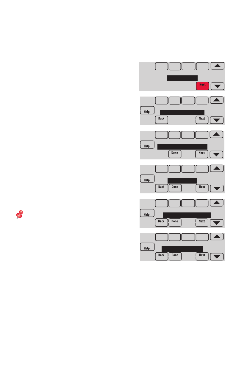
Performing installer setup
Setup options define the type of system you are installing and preferences for the
display.
1 Follow prompts on the screen to select the appropriate options. Among the
screens you might see will be options for:
1.1 Application, either Residential or
Commercial.
1.2 Thermostat Name, which will enable
you to identify it if you’re installing
more than one thermostat (for a zoned
HVAC application, for instance).
1.3 Thermostat Type, either programmable
or not, depending on preference.
1.4 Temperature scale, either Fahrenheit
or Celsius.
1.5 Use outdoor temp.
NOTE: Choose WIRED/SENSOR if your
application will require a wired sensor, or
will use the Internet for weather data.
1.6 The type of heating system.
1.7 For all installer options, press the s or
t buttons to change the option.
1.8 Press Next to move to the next setting,
and Done when setup is complete.
APPLICATION
residential
THERMOSTAT NAME
THERMOSTAT
THERMOSTAT TYPE
programmable
TEMPERATURE SCALE
fahrenheit
USE OUTDOOR TEMP
wired / sensor
HEATING SYSTEM
conv. forced air
5
 Loading...