


 Loading...
UDC3200
Universal Digital Controller
Operator Manual
51-52-25-143 April 2008
Honeywell Process Solutions

Notices and Trademarks
Copyright 2008 by Honeywell
April 2008
WARRANTY/REMEDY
Honeywell warrants goods of its manufacture as being free of defective materials and faulty workmanship. Contact your local sales office for warranty information. If warranted goods are returned to Honeywell during the period of coverage, Honeywell will repair or replace without charge those items it finds defective. The foregoing is Buyer's sole remedy and is in lieu of all other warranties, expressed or implied, including those of merchantability and fitness for a particular purpose. Specifications may change without notice. The information we supply is believed to be accurate and reliable as of this printing. However, we assume no responsibility for its use.
While we provide application assistance personally, through our literature and the Honeywell web site, it is up to the customer to determine the suitability of the product in the application.
Contacts
World Wide Web
The following lists Honeywell’s World Wide Web sites that will be of interest to our customers.
Honeywell Organization |
WWW Address (URL) |
|
|
Corporate |
http://www.honeywell.com |
Honeywell Process Solutions |
http://hpswebhoneywell.com |
|
|
Telephone
Contact us by telephone at the numbers listed below.
|
Organization |
Phone Number |
|
|
|
|
|
United States and Canada |
Honeywell |
1-800-423-9883 |
Tech. Support |
|
|
1-800-525-7439 |
Service |
Web
http://content.honeywell.com/ipc/faq/
Honeywell Process Solutions
512 Virginia Drive
Fort Washington, PA 19034
UDC3200 is a U.S. registered trademark of Honeywell
Other brand or product names are trademarks of their respective owners.
4/08 |
UDC3200 Universal Digital Controller Operator Manual |
ii |
Symbol Definitions
The following table lists those symbols used in this document to denote certain conditions.
Symbol |
Definition |
|
|
This CAUTION symbol on the equipment refers the user to the Product Manual for additional information. This symbol appears next to required information in the manual.
WARNING
PERSONAL INJURY: Risk of electrical shock. This symbol warns the user of a potential shock hazard where HAZARDOUS LIVE voltages greater than 30 Vrms, 42.4 Vpeak, or 60 VDC may be accessible. Failure to comply with these instructions could result in death or serious injury.
ATTENTION, Electrostatic Discharge (ESD) hazards. Observe precautions for handling electrostatic sensitive devices
Protective Earth (PE) terminal. Provided for connection of the protective earth (green or green/yellow) supply system conductor.
Functional earth terminal. Used for non-safety purposes such as noise immunity improvement. NOTE: This connection shall be bonded to protective earth at the source of supply in accordance with national local electrical code requirements.
Earth Ground. Functional earth connection. NOTE: This connection shall be bonded to Protective earth at the source of supply in accordance with national and local electrical code requirements.
Chassis Ground. Identifies a connection to the chassis or frame of the equipment shall be bonded to Protective Earth at the source of supply in accordance with national and local electrical code requirements.
4/08 |
UDC3200 Universal Digital Controller Operator Manual |
iii |

|
|
|
Contents |
|
1 |
INTRODUCTION ................................................................................................... |
1 |
||
1.1 |
|
Operator Interface ........................................................................................................................... |
1 |
|
1.2 |
|
Function of Displays and Keys ....................................................................................................... |
1 |
|
1.3 |
|
CE Conformity (Europe)................................................................................................................. |
2 |
|
2 |
INSTALLATION..................................................................................................... |
5 |
||
2.1 |
|
Pre-installation Information ............................................................................................................ |
5 |
|
2.2 |
|
Model Number Interpretation ......................................................................................................... |
5 |
|
2.3 |
|
Control and Alarm Relay Contact Information............................................................................... |
6 |
|
2.4 |
|
Mounting......................................................................................................................................... |
7 |
|
2.5 |
|
Wiring ............................................................................................................................................. |
9 |
|
|
2.5.1 |
Electrical Considerations ..................................................................................................... |
9 |
|
2.6 |
|
Wiring Diagrams........................................................................................................................... |
10 |
|
3 |
CONFIGURATION............................................................................................... |
24 |
||
3.1 |
|
Configuration Prompt Hierarchy .................................................................................................. |
24 |
|
3.2 |
|
Configuration Procedure............................................................................................................... |
25 |
|
3.3 |
|
Tuning Set Up Group.................................................................................................................... |
26 |
|
3.4 |
|
SP Ramp Set Up Group ................................................................................................................ |
29 |
|
3.5 |
|
Accutune Set Up Group ................................................................................................................ |
32 |
|
3.6 |
|
Algorithm Set Up Group............................................................................................................... |
33 |
|
3.7 |
|
Output Set Up Group .................................................................................................................... |
39 |
|
3.8 |
|
Input 1 Set Up Group.................................................................................................................... |
42 |
|
3.9 |
|
Input 2 Set Up Group.................................................................................................................... |
45 |
|
3.10 Control Set Up Group ............................................................................................................... |
48 |
|||
3.11 |
Options Group ........................................................................................................................... |
53 |
||
3.12 |
Communications Group ............................................................................................................ |
57 |
||
3.13 Alarms Set Up Group ................................................................................................................ |
59 |
|||
3.14 Display Set Up Group ............................................................................................................... |
63 |
|||
4 |
MONITORING AND OPERATING THE CONTROLLER..................................... |
65 |
||
4.1 |
|
Operator Interface ......................................................................................................................... |
65 |
|
4.2 |
|
Entering a Security Code .............................................................................................................. |
65 |
|
4.3 |
|
Individual key lockout .................................................................................................................. |
66 |
|
4.4 |
|
Monitoring Your Controller.......................................................................................................... |
67 |
|
|
4.4.1 |
Annunciators ...................................................................................................................... |
67 |
|
|
4.4.2 Viewing the operating parameters...................................................................................... |
68 |
||
|
4.4.3 |
Diagnostic Messages.......................................................................................................... |
69 |
|
4.5 |
|
Accutune III .................................................................................................................................. |
71 |
|
|
4.5.1 Tune for Simplex Outputs.................................................................................................. |
72 |
||
|
|
|
|
|
4/08 |
|
|
UDC3200 Universal Digital Controller Operator Manual |
iv |

|
4.5.2 Tune for Duplex (Heat/Cool)............................................................................................. |
73 |
|
4.5.3 Using AUTOMATIC TUNE at start-up for Duplex (Heat/Cool) ...................................... |
74 |
|
4.5.4 Using BLENDED TUNE at start-up for Duplex (Heat/Cool) ........................................... |
75 |
|
4.5.5 Using MANUAL TUNE at start-up for Duplex (Heat/Cool)............................................. |
75 |
|
4.5.6 Error Codes ........................................................................................................................ |
77 |
4.6 |
Fuzzy Overshoot Suppression....................................................................................................... |
78 |
5 |
TROUBLESHOOTING/SERVICE........................................................................ |
79 |
5.1 |
Background Tests.......................................................................................................................... |
79 |
5.2 |
Controller Failure Symptoms........................................................................................................ |
81 |
6 |
SALES AND SERVICE........................................................................................ |
82 |
v |
UDC3200 Universal Digital Controller Operator Manual |
4/08 |
1 Introduction
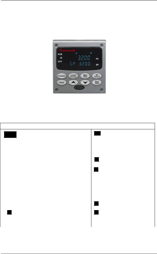
1.1 Operator Interface
Figure 1-1 UDC3200 Operator Interface
1.2 Function of Displays and Keys
Table 1-1 Function of Displays and Keys
Display Indicators
3200 |
Upper display with 4 large digits shows |
Process Variable value (normal operation) |
|
|
and special annunciator features. During |
|
Configuration, the upper display provides |
|
guidance for the operator through prompts (7 |
|
– characters) |
|
|
|
|
During normal operation, the lower display |
SP 3200 |
||||
|
|
|
|
shows key-selected operating parameters |
|
|
|
|
|
|
|
|
|
such as Output, Setpoints, Inputs, Deviation, |
|
|
|
|
active Tuning Parameter Set, Timer Status, or |
|
|
|
|
minutes remaining in a setpoint ramp (4 |
|
|
|
|
digits). During configuration, the lower display |
|
|
|
|
provides guidance for the operator through |
|
|
|
|
prompts (8-characters). |
|
|
|
|
Indicates Alarm 1 and/or Alarm 2 conditions |
|
ALM |
|
||
|
|
|
|
exist. |
|
|
|
|
|
|
|
|
Indicates Digital Input 1 and/or 2 on. |
|
|
|
DI |
|
|
OUT Indicates Control Relay 1 and/or 2 on.
|
F |
|
|
Or |
Indicates either degrees |
||
|
|
Fahrenheit or Centigrade. |
|
|
C |
|
|
MAN |
|
|
Or |
Indicates either Manual or Auto |
|
A |
|
mode. |
|
Indicates Local Setpoint #1. |
|
SP |
|
|
|
|
Also, a bar is lighted when the |
|
|
setpoint being used is shown on |
|
|
the lower display. |
04/08 |
UDC3200 Universal Digital Controller Operator Manual |
1 |

Keys and Functions
Function |
Selects functions within each |
|
configuration group. |
||
|
Scrolls through the configuration Setup groups.
Lower |
Returns Controller to normal display |
Display |
from Set Up mode. Toggles various |
|
operating parameters for display. |
|
Increases setpoint or output value. Increases the configuration values or changes functions in Configuration mode groups.
Infrared transceiver
Man
Auto
SP
Select
Run
Hold
Selects Manual or Auto mode.
Hold key down to cycle through configured setpoints.
Enables Run/Hold of the SP Ramp or Program plus Timer start.
Decreases setpoint or output value. Decreases the configuration values or changes functions in Configuration mode groups.
NEMA4X and IP66 screw attachment (each corner)
1.3 CE Conformity (Europe)
This product is in conformity with the protection requirements of the following European Council Directives: 73/23/EEC, the Low Voltage Directive, and 89/336/EEC, the EMC Directive. Conformity of this product with any other “CE Mark” Directive(s) shall not be assumed.
Product Classification: Class I: Permanently connected, panel-mounted Industrial Control Equipment with protective earthing (grounding) (EN61010-1).
Enclosure Rating: This controller must be panel-mounted with the rear terminals enclosed within the panel. The front panel of the controller is rated at NEMA4X and IP66 when properly installed.
Installation Category (Overvoltage Category): Category II (EN61010-1)
Pollution Degree: Pollution Degree 2: Normally non-conductive pollution with occasional conductivity caused by condensation. (Ref. IEC 664-1)
EMC Classification: Group 1, Class A, ISM Equipment (EN61326, emissions), Industrial Equipment (EN61326, immunity)
Method of EMC Assessment: Technical File (TF) Declaration of Conformity: 51453663
Deviation from the installation conditions specified in this manual, and the special conditions for CE conformity in Subsection 2, may invalidate this product’s conformity with the Low Voltage and EMC Directives.
2 |
UDC3200 Universal Digital Controller Operator Manual |
04/08 |

ATTENTION
The emission limits of EN61326 are designed to provide reasonable protection against harmful interference when this equipment is operated in an industrial environment. Operation of this equipment in a residential area may cause harmful interference. This equipment generates, uses, and can radiate radio frequency energy and may cause interference to radio and television reception when the equipment is used closer than 30 meters (98 feet) to the antenna(e). In special cases, when highly susceptible apparatus is used in close proximity, the user may have to employ additional mitigating measures to further reduce the electromagnetic emissions of this equipment.
WARNING
If this equipment is used in a manner not specified by the manufacturer, the protection provided by the equipment may be impaired.
04/08 |
UDC3200 Universal Digital Controller Operator Manual |
3 |
2Installation
2.1Pre-installation Information
If the controller has not been removed from its shipping carton, inspect the carton for damage then remove the controller.
•Inspect the unit for any obvious shipping damage and report any damage due to transit to the carrier.
•Make sure a bag containing mounting hardware is included in the carton with the controller.
•Check that the model number shown on the inside of the case agrees with what you have ordered.
2.2Model Number Interpretation
Write your controller’s model number in the spaces provided below and circle the corresponding items in each table. This information will also be useful when you wire your controller.
Instructions
Select the desired key number. The arrow to the right marks the selection available.
Make the desired selections from Tables I through VI using the column below the
proper arrow. |
|
A dot ( |
) denotes availability. |
|
|
|
|
|
|
||||
Key Number |
|
I |
|
II |
|
III |
|
IV |
V |
|
VI |
||
_ _ _ _ _ _ |
- |
_ _ |
- |
_ _ _ _ |
- |
_ _ _ |
- |
_ _ _ _ _ |
- |
_ _ |
|
_ |
|
KEY NUMBER - UDC3200 Single Loop Controller
Description
Digital Controller for use with 90 to 264Vac Power Digital Controller for use with 24Vac/dc Power
TABLE I - Specify Control Output and/or Alarms
Selection Availability
DC3200
DC3201
|
Current Output (4 to 20ma, 0 to 20 ma) |
|
Electro Mechanical Relay (5 Amp Form C) |
Output #1 |
Solid State Relay (1 Amp) |
|
Open Collector transistor output |
|
Dual 2 Amp Relays (Both are Form A) (Heat/Cool Applications) |
|
No Additional Outputs or Alarms |
Output #2 and Alarm |
One Alarm Relay Only |
#1 or Alarms 1 and 2 |
E-M Relay (5 Amp Form C) Plus Alarm 1 (5 Amp Form C Relay) |
|
Solid State Relay (1 Amp) Plus Alarm 1 (5 Amp Form C Relay) |
|
Open Collector Plus Alarm 1 (5 Amp Form C Relay) |
C _ E _ A _ T _ R _
_ 0 _ B _ E _ A _ T
TABLE II - Communications and Software Selections
|
None |
|
Communications |
Auxiliary Output/Digital Inputs (1 Aux and 1 DI or 2 DI) |
|
RS-485 Modbus Plus Auxiliary Output/Digital Inputs |
||
|
||
|
10 Base-T Ethernet (Modbus RTU) Plus Auxiliary Output/Digital Inputs |
|
|
Standard Functions, Includes Accutune |
|
Software Selections |
Math Option |
|
|
Set Point Programming (1 Program, 12 Segments) |
|
|
Set Point Programming Plus Math |
|
Reserved |
No Selection |
|
Infrared interface |
Infrared Interface Included (Can be used with a Pocket PC) |
0 _ _ _
1 _ _ _
2 _ _ _
3 _ _ _
_ 0 _ _ _ A _ _ _ B _ _ _ C _ _
_ _ 0 _
_ _ _ R
TABLE III - Input 1 can be changed in the field using external resistors
|
TC, RTD, mV, 0-5V, 1-5V |
|
Input 1 |
TC, RTD, mV, 0-5V, 1-5V, 0-20mA, 4-20mA |
|
TC, RTD, mV, 0-5V, 1-5V, 0-20mA, 4-20mA, 0-10V |
||
|
||
|
Carbon, Oxygen or Dewpoint (Requires Input 2) |
|
|
None |
|
Input 2 |
TC, RTD, mV, 0-5V, 1-5V, 0-20mA, 4-20mA |
|
TC, RTD, mV, 0-5V, 1-5V, 0-20mA, 4-20mA, 0-10V |
||
|
||
|
Slidewire Input (Requires two Relay Outputs) |
1 _ _
2 _ _
3 _ _
1 6 0
_ 00 _ 10 _ 20 _ 40
04/08 |
UDC3200 Universal Digital Controller Operator Manual |
5 |
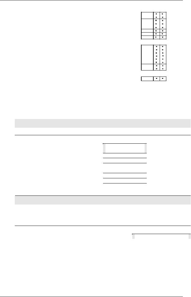
TABLE IV - Options
Approvals |
CE (Standard) |
|
CE, UL and CSA |
||
|
||
Tags |
None |
|
Linen Customer ID Tag - 3 lines w/22 characters/line |
||
|
Stainless Steel Customer ID Tag - 3 lines w/22 characters/line |
|
Future Options |
None |
|
None |
||
|
None |
TABLE V - Product Manuals
|
Product Information on CD - All Languages |
|
|
English Manual |
|
Manuals |
French Manual |
|
German Manual |
||
|
||
|
Italian Manual |
|
|
Spanish Manual |
|
Certificate |
None |
|
Certificate of Conformance (F3391) |
||
|
||
TABLE VI |
|
No Selection |
None |
0 _ _ _ _
1 _ _ _ _
_ 0 _ _ _
_ T _ _ _
_ S _ _ _
_ _ 0 _ _
_ _ _ 0 _
_ _ _ _ 0
0 _
E_
F_
G_
I _
S _
_ 0 _ C
0 _
Figure 2-1 Model Number Interpretation
2.3 Control and Alarm Relay Contact Information
Control Relays
ATTENTION
Control relays operate in the standard control mode (that is, energized when output state is on).
Table 2-1 Control Relay Contact Information
|
Unit Power |
Control Relay |
|
Control Relay |
|
Output #1 or #2 |
|
|
Wiring |
|
Contact |
|
Indicator Status |
|
Off |
N.O. |
|
Open |
|
Off |
|
|
N.C. |
|
Closed |
|
|
|
On |
N.O. |
|
Open |
|
Off |
|
|
|
|
Closed |
|
On |
|
|
N.C. |
|
Closed |
|
Off |
|
|
|
|
Open |
|
On |
Alarm Relays
ATTENTION
Alarm relays are designed to operate in a failsafe mode (that is, de-energized during alarm sate). This results in alarm actuation when power is OFF or when initially applied, until the unit completes self-diagnostics. If power is lost to the unit, the alarms will de-energize and thus the alarm contacts will close.
Table 2-2 Alarm Relay Contact Information
|
Unit |
|
|
Alarm Relay |
|
Variable NOT in Alarm State |
|
Variable in Alarm State |
|
||
|
Power |
|
|
Wiring |
|
Relay |
Indicators |
|
Relay |
Indicators |
|
|
|
|
|
|
|
Contact |
|
|
Contact |
|
|
|
Off |
|
N.O. |
Open |
Off |
|
Open |
Off |
|
||
|
|
|
|
N.C. |
Closed |
|
|
Closed |
|
|
|
|
On |
|
N.O. |
Closed |
Off |
|
Open |
On |
|
||
|
|
|
|
N.C. |
Open |
|
|
Closed |
|
|
|
6 |
UDC3200 Universal Digital Controller Operator Manual |
04/08 |

2.4 Mounting
Physical Considerations
The controller can be mounted on either a vertical or tilted panel using the mounting kit supplied. Adequate access space must be available at the back of the panel for installation and servicing activities.
•Overall dimensions and panel cutout requirements for mounting the controller are shown in Figure 2-2.
•The controller’s mounting enclosure must be grounded according to CSA standard C22.2 No. 0.4 or Factory Mutual Class No. 3820 paragraph 6.1.5.
•The front panel is moisture rated NEMA3 and IP55 rated and can be easily upgraded to NEMA4X and IP66.
Overall Dimensions
|
Max. panel thickness |
||||
mm |
19,1 |
|
|
|
|
9,0 |
|
||||
.75 |
|
||||
inches |
0,35 |
|
|||
|
|
||||
|
|
|
|
|
|
|
|
|
|
|
|
|
|
|
|
|
|
92,0 + 0,8 - 0,00
3,62 + 0,03 -0,00
90,6 108,6 3,57 4,28
Panel
Cutout
|
|
|
|
|
|
|
|
|
92,0 |
+ 0,8 |
|
|
|
|
|
|
|
|
|
|
|
|
113,1 |
|||
|
- 0,00 |
|
|
|
|
|
||
|
17,9 |
4,45 |
||||||
3,62 |
+ 0,03 |
|||||||
|
||||||||
0,70 |
|
|||||||
|
-0,00 |
|
||||||
|
|
|
|
|
|
|
||
Figure 2-2 Mounting Dimensions (not to scale)
04/08 |
UDC3200 Universal Digital Controller Operator Manual |
7 |
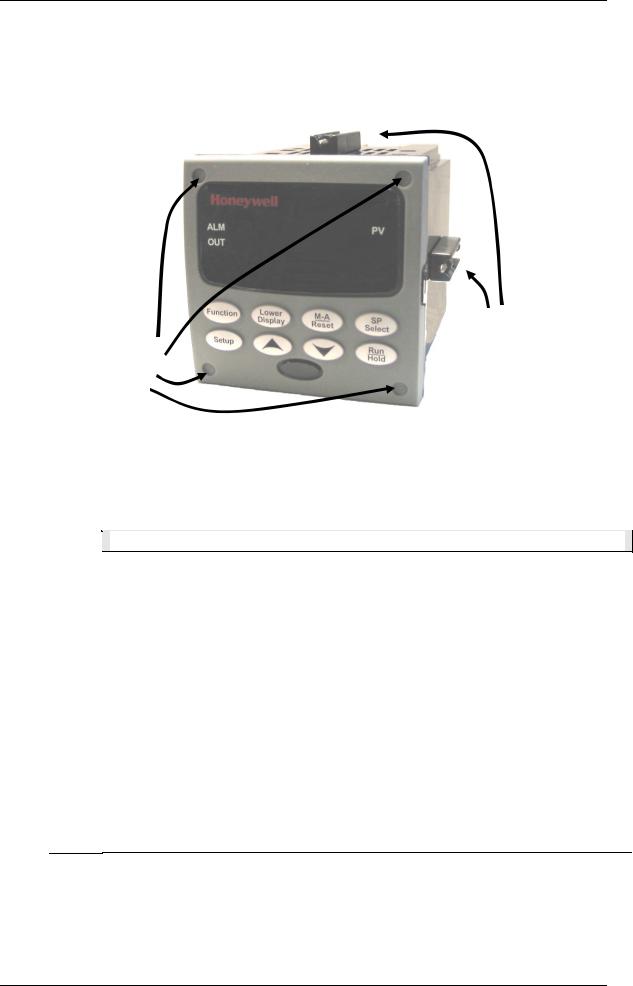
Mounting Method
Before mounting the controller, refer to the nameplate on the outside of the case and make a note of the model number. It will help later when selecting the proper wiring configuration.
Mounting clips
Attach screws and washers here for water protection
|
|
|
|
Figure 2-3 Mounting Methods |
Mounting Procedure |
|
|||
|
|
|
|
Table 2-3 Mounting Procedure |
|
|
|
|
|
|
Step |
|
|
Action |
1Mark and cut out the controller hole in the panel according to the dimension information in Figure 2-2.
2Orient the case properly and slide it through the panel hole from the front.
3Remove the mounting kit from the shipping container and install the kit as follows:
•For normal installation two mounting clips are required. Insert the prongs of the clips into the two holes in the top and bottom center of the case
•For water-protected installation four mounting clips are required. There are two options of where to install the mounting clips:
1)Insert the prongs of the clips into the two holes on the left and right side of the top and bottom of the case or
2)on the center on each of the four sides.
•Tighten screws to 2 lb-inch (22 N•cm) to secure the case against the panel. CAUTION: Over tightening will cause distortion and the unit may not seal properly.
4For water-protected installation, install four screws with washers into the four recessed areas in the corners of the front bezel (Figure 2-3). Push the point of the screw through the center piercing the elastomeric material and then tighten screws to 5 lb-in (56 N•cm).
8 |
UDC3200 Universal Digital Controller Operator Manual |
04/08 |

2.5 Wiring
2.5.1 Electrical Considerations
Line voltage wiring
This controller is considered “rack and panel mounted equipment” per EN61010-1, Safety Requirements for Electrical Equipment for Measurement, Control, and Laboratory Use, Part 1: General Requirements. Conformity with 72/23/EEC, the Low Voltage Directive requires the user to provide adequate protection against a shock hazard. The user shall install this controller in an enclosure that limits OPERATOR access to the rear terminals.
Mains Power Supply
This equipment is suitable for connection to 90 to 264 Vac or to 24 Vac/dc 50/60 Hz, power supply mains. It is the user’s responsibility to provide a switch and non-time delay (North America), quick-acting, high breaking capacity, Type F (Europe), 1/2A, 250V fuse(s), or circuit-breaker for 90-264 Vac applications; or 1 A, 125 V fuse or circuit breaker for 24 Vac/dc applications, as part of the installation. The switch or circuit-breaker shall be located in close proximity to the controller, within easy reach of the OPERATOR. The switch or circuit-breaker shall be marked as the disconnecting device for the controller.
CAUTION |
Applying 90-264 Vac to an instrument rated for 24 Vac/dc will |
|
|
|
|
|
severely damage the instrument and is a fire and smoke hazard. |
When applying power to multiple instruments, make certain that sufficient current is supplied. Otherwise, the instruments may not start up normally due to the voltage drop caused by the in-rush current.
Controller Grounding
PROTECTIVE BONDING (grounding) of this controller and the enclosure in which it is installed shall be in accordance with National and Local electrical codes. To minimize electrical noise and transients that may adversely affect the system, supplementary bonding of the controller enclosure to a local ground, using a No. 12 (4 mm2) copper conductor, is recommended.
Control/Alarm Circuit Wiring
The insulation of wires connected to the Control/Alarm terminals shall be rated for the highest voltage involved. Extra Low Voltage (ELV) wiring (input, current output, and low voltage Control/Alarm circuits) shall be separated from HAZARDOUS LIVE (>30 Vac, 42.4 Vpeak, or 60 Vdc) wiring per Permissible Wiring Bundling, Table 2-4.
Electrical Noise Precautions
Electrical noise is composed of unabated electrical signals which produce undesirable effects in measurements and control circuits.
Digital equipment is especially sensitive to the effects of electrical noise. Your controller has built-in circuits to reduce the effect of electrical noise from various sources. If there is a need to further reduce these effects:
04/08 |
UDC3200 Universal Digital Controller Operator Manual |
9 |

•Separate External Wiring—Separate connecting wires into bundles
(See Permissible Wiring Bundling - Table 2-4) and route the individual bundles through separate conduit metal trays.
Use Suppression Devices—For additional noise protection, you may want to add suppression devices at the external source. Appropriate suppression devices are commercially available.
ATTENTION
For additional noise information, refer to document number 51-52-05-01, How to Apply Digital Instrumentation in Severe Electrical Noise Environments.
Permissible Wiring Bundling
Table 2-4 Permissible Wiring Bundling
Bundle No. |
|
Wire Functions |
1• Line power wiring
•Earth ground wiring
•Line voltage control relay output wiring
•Line voltage alarm wiring
2Analog signal wire, such as:
•Input signal wire (thermocouple, 4 to 20 mA, etc.)
•4-20 mA output signal wiring
Digital input signals
3• Low voltage alarm relay output wiring
•Low voltage wiring to solid state type control circuits
•Low voltage wiring to open collector type control circuits
2.6Wiring Diagrams
Universal Output Functionality and Restrictions
Instruments with multiple outputs can be configured to perform a variety of output types and alarms. For example, an instrument with a current output and two relays can be configured to perform any of the following:
1)Current Simplex with two alarm relays;
2)Current Duplex 100% with two alarm relays;
3)Time Simplex with one alarm relay;
4)Time Duplex with no alarm relays; or
5)Three Position Step Control with no alarm relays.
These selections may all be made via the keyboard and by wiring to the appropriate output terminals; there are no internal jumpers or switches to change. This flexibility allows a customer to stock a single instrument which is able to handle a variety of applications.
Table 2-5 shows what control types and alarms are available based upon the installed outputs. In this table, when Duplex Control and Reverse Action are configured, “Output 1” is HEAT while “Output 2” is COOL. When Three Position Step Control is configured, “Output 1” is OPEN while “Output 2” is CLOSE. The Output 1/2 option “Single Relay” can be any of the following selections: Electro-Mechanical Relay, Solid-State Relay or Open Collector Output.
Table 2-5 Universal Output Functionality and Restrictions
10 |
UDC3200 Universal Digital Controller Operator Manual |
04/08 |

|
Output Algorithm |
|
|
Output 1/2 |
|
|
Function of |
|
|
Function of Other Outputs |
||||
|
Type |
|
|
Option |
|
|
Output 1/2 |
|
|
Output #3 |
|
Output #4 |
|
Auxiliary Output |
Time Simplex |
Single Relay |
|
Output 1 |
|
Alarm 2 |
|
Alarm 1 |
|
Not Needed |
|||||
|
|
|
Current Output |
|
INU |
|
Output 1 |
|
Alarm 1 |
|
Not Needed |
|||
|
|
|
Dual Relay |
|
Output 1 |
|
Alarm 2 |
|
Alarm 1 |
|
Not Needed |
|||
Time Duplex or |
Single Relay |
|
Output 1 |
|
Output 2 |
|
Alarm 1 |
|
Not Needed |
|||||
TPSC or Position |
Current Output |
|
INU |
|
Output 2 |
|
Output 1 |
|
Not Needed |
|||||
Proportional |
|
|
|
|
|
|
|
|
|
|
|
|
||
Dual Relay |
|
Outputs 1 and |
|
Alarm 2 |
|
Alarm 1 |
|
Not Needed |
||||||
|
|
|
|
|
|
|
||||||||
|
|
|
|
|
|
2 |
|
|
|
|
|
|
|
|
Current Simplex |
Single Relay |
|
INU |
|
Alarm 2 |
|
Alarm 1 |
|
Output 1 |
|||||
|
|
|
Current Output |
|
Output 1 |
|
Alarm 2 |
|
Alarm 1 |
|
Not Needed |
|||
|
|
|
Dual Relay |
|
INU |
|
Alarm 2 |
|
Alarm 1 |
|
Output 1 |
|||
Current Dup. 100% |
Single Relay |
|
INU |
|
Alarm 2 |
|
Alarm 1 |
|
Outputs 1 and 2 |
|||||
Current = COOL |
Current Output |
|
Outputs 1 and |
|
Alarm 2 |
|
Alarm 1 |
|
Not Needed |
|||||
and HEAT |
|
|
|
2 |
|
|
|
|
|
|
|
|||
|
|
|
Dual Relay |
|
INU |
|
Alarm 2 |
|
Alarm 1 |
|
Outputs 1 and 2 |
|||
Current Duplex |
Single Relay |
|
N/A |
|
N/A |
|
N/A |
|
N/A |
|||||
50% |
|
Current Output |
|
Output 1 |
|
Alarm 2 |
|
Alarm 1 |
|
Output 2 |
||||
Current = HEAT |
|
|
|
|
|
|
|
|
|
|
|
|
||
Dual Relay |
|
N/A |
|
N/A |
|
N/A |
|
N/A |
||||||
Aux Out = COOL |
|
|
|
|
||||||||||
|
|
|
|
|
|
|
|
|
|
|
|
|||
Current/Time |
Single Relay * |
|
Output 1 |
|
Output 2 |
|
Alarm 1 |
|
Output 2 |
|||||
Current = COOL |
Current Output |
|
Output 2 |
|
Output 2 |
|
Alarm 1 |
|
Not Needed |
|||||
Time = HEAT |
Dual Relay * |
|
Outputs 1 & 2 |
|
Alarm 2 |
|
Alarm 1 |
|
Output 2 |
|||||
Time/Current |
Single Relay * |
|
Output 1 |
|
Output 2 |
|
Alarm 1 |
|
Output 1 |
|||||
Time = COOL |
Current Output |
|
Output 1 |
|
Output 2 |
|
Alarm 1 |
|
Not Needed |
|||||
Current = HEAT |
Dual Relay * |
|
Outputs 1 & 2 |
|
Alarm 2 |
|
Alarm 1 |
|
Output 1 |
|||||
TPSC = Three Position Step Control
N/A = Not Available – This output algorithm type cannot be performed with this Output 1/2 option.
INU = Installed, Not Used – The installed Output 1/2 option is not used for the configured output algorithm type.
Not Needed = Auxiliary Output is Not Needed to provide the desired output algorithm and can be used for another purpose. With the proper configuration, Auxiliary Output could also be used as a substitute for the Current Output.
*To obtain this output algorithm type with these Output 1/2 Options: 1) Configure the OUTALG selection as “TIME D”; 2) Configure Auxiliary Output for “OUTPUT” and; 3) Scale the Auxiliary Output as necessary for the desired output algorithm type. For these selections, the Output 1 (HEAT) and Output 2 (COOL) signals will be present both on the Auxiliary Output and on the two relays normally used for Time Duplex.
04/08 |
UDC3200 Universal Digital Controller Operator Manual |
11 |
Wiring the Controller
|
|
|
7 |
|
|
|
10 |
19 |
|
1 |
L1 |
11 |
20 |
4 |
|
L2/N |
12 |
21 |
|
|
4 |
13 |
22 |
|
2 |
5 |
14 |
23 |
5 |
|
6 |
15 |
24 |
|
3 |
7 |
16 |
25 |
|
8 |
17 |
26 |
6 |
|
|
9 |
18 |
27 |
|
8
See table for callout details
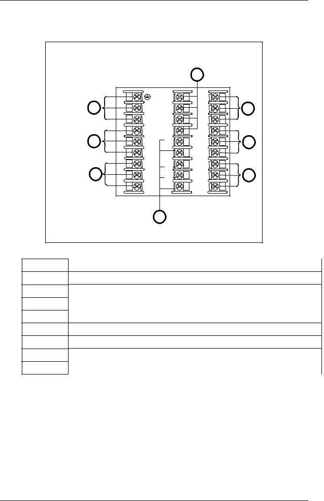
Figure 2-4 Composite Wiring Diagram
Callout |
Details |
1AC/DC Line Voltage Terminals. See Figure 2-5.
2Output 3 Terminals. See Figure 2-8 through Figure 2-14.
3Output 4 Terminals. See Figure 2-8 through Figure 2-14.
4Outputs 1 and 2 Terminals. See Figure 2-8 through Figure 2-14.
5Input #2 Terminals. See Figure 2-7.
6Input #1 Terminals. See Figure 2-6.
7Aux. Output and Digital Inputs Terminals. See Figure 2-17.
8Communications Terminals. See Figure 2-15 and Figure 2-16.
12 |
UDC3200 Universal Digital Controller Operator Manual |
04/08 |
|
1 |
Earth |
|
|
3 |
Ground |
10 |
19 |
|
2 |
Hot |
|||
AC/DC |
|
11 |
20 |
|
|
L1 |
|||
Line |
|
Neutral |
12 |
21 |
Voltage |
|
L2/N |
||
|
|
4 |
13 |
22 |
|
|
|
||
|
|
5 |
14 |
23 |
|
|
|
||
|
|
6 |
15 |
24 |
|
|
|
||
|
|
7 |
16 |
25 |
|
|
|
||
|
|
8 |
17 |
26 |
|
|
|
||
|
|
9 |
18 |
27 |
|
|
|
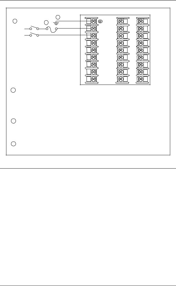
1PROTECTIVE BONDING (grounding) of this controller and the enclosure in which it is installed, shall be in accordance with National and local electrical codes. To minimize
electrical noise and transients that may adversely affect the system, supplementary bonding of the controller enclosure to local ground using a No. 12 (4 mm2) copper conductor is recommended. Before powering the controller, see “Prelimnary Checks” in this section of the Product Manual.
2It is the user’s responsibility to provide a switch and non-time delay (North America), quick-acting, high breaking capacity, Type F (Europe), 1/2A, 250V fuse(s), or circuitbreaker for 90-264 Vac applications; or 1 A, 125 V fuse or circuit breaker for 24 Vac/dc applications, as part of the installation.
3CAUTION Applying 90-264 Vac to an instrument rated for 24 Vac/dc will severely
damage the instrument and is a fire and smoke hazard.
Figure 2-5 Mains Power Supply
04/08 |
UDC3200 Universal Digital Controller Operator Manual |
13 |
Input #1
Thermocouple |
RTD |
Millivolt or Volts |
|||
except 0-10 Volts |
|||||
|
|
||||
Use Thermocouple |
|
|
|
|
|
extension wire only |
|
source |
|
25 R |
|
25 R |
25 R |
|
|||
|
|
||||
3 |
|
|
+ |
|
|
26 + |
26 + |
mV or |
26 + |
||
|
|
Volt |
|
|
|
27 – |
27 – |
source |
– |
27 – |
|
0-10 Volts |
Milliamps |
Thermocouple Differential |
|||
0–10 + |
100K 1 |
|
Volt |
1 |
2 |
source |
|
|
|
|
|
–100K 3
|
|
|
|
|
|
|
Use Thermocouple |
|
|
|
25 |
R |
– |
|
|
|
25 R |
extension wire only |
25 |
R |
|
|
|
|
+ |
|
||||||
|
|
Xmitter |
1 |
|
|
|
|
|||
26 |
+ |
+ |
|
26 + |
|
4 |
26 |
+ |
||
250 |
|
Ω |
– |
|||||||
|
|
|
|
|
2 |
|
|
|||
27 |
– |
|
Power |
|
|
27 – |
– |
27 |
– |
|
|
+ – |
|
|
|||||||
|
|
|
Supply |
|
|
|
+ |
|
|
|
1The 250 ohm resistor for milliamp inputs or the voltage divider for 0-10 Volt inputs are supplied with the controller when those inputs are specified. These items must be installed prior to start up when the controller is wired. For 0-20 mA applications, the resistor should be located at the transmitter terminals if Burnout detection is desired.
2Splice and tape this junction between the two thermocouples. This junction may be located anywhere between the thermocouples and the instrument terminals, it does not need to be close to the other thermocouple junctions. Both thermocouples must be of the same type. For best accuracy, the two thermocouples should be matched or, preferably, made from the same batch of wire.
3This controller does not produce a steady current for burnout detection. For that reason, when a thermocouple is used in parallel with another instrument, it may be desirable to configure the burnout selection for this controller to “NOFS” and use the burnout current from the other instrument to also drive this controller.
4The millivolt values for the Thermocouple Differential Input are for a pair of J thermocouples at an ambient temperature mean of 450°F / 232°C.
Figure 2-6 Input 1 Connections
14 |
UDC3200 Universal Digital Controller Operator Manual |
04/08 |
Input #2
Thermocouple |
RTD |
|
Millivolt or Volts |
||
|
except 0-10 Volts |
||||
|
|
|
|||
Use Thermocouple |
|
|
|
|
|
extension wire only |
22 |
R |
source |
|
22 R |
22 R |
|
||||
|
|
||||
3 |
|
|
|
+ |
|
23 + |
23 |
+ |
mV or |
23 + |
|
|
|
|
Volt |
|
|
24 – |
24 |
– |
source |
– |
24 – |
0-10 Volts |
Milliamps |
|
Thermocouple Differential |
||
0–10 |
+ |
100K 1 |
|
|
|
Volt |
1 |
2 |
source |
|
|
|
|
–100K 3
|
|
|
|
|
Use Thermocouple |
|
|
|
22 |
R |
– |
|
22 R |
extension wire only |
22 |
R |
|
|
+ |
|
||||||
|
|
Xmitter |
1 |
|
|
|
|
|
23 |
+ |
+ |
23 + |
– |
|
23 |
+ |
|
Ω |
|
|||||||
|
|
250 |
|
2 |
|
|
||
24 |
– |
Power |
|
24 – |
– |
24 |
– |
|
+ – |
|
|||||||
|
|
Supply |
|
|
+ |
|
|
|
Slidewire Input
(for Position Proportional Control or Three Position Step Control)
|
4 |
|
Open |
22 |
R |
Wiper |
23 |
+ |
Close |
24 |
– |
1The 250 ohm resistor for milliamp inputs or the voltage divider for 0-10 Volt inputs are supplied with the controller when those inputs are specified. These items must be installed prior to start up when the controller is wired. For 0-20 mA applications, the resistor should be located at the transmitter terminals if Burnout detection is desired.
2Splice and tape this junction between the two thermocouples. This junction may be located anywhere between the thermocouples and the instrument terminals, it does not need to be close to the other thermocouple junctions. Both thermocouples must be of the same type. For best accuracy, the two thermocouples should be matched or, preferably, made from the same batch of wire.
3This controller does not produce a steady current for burnout detection. For that reason, when a thermocouple is used in parallel with another instrument, it may be desirable to configure the burnout selection for this controller to “NOFS” and use the burnout current from theother instrument to also drive this controller.
4 Input 2 is used to measure the Slidewire Input for Position Proportional Control. |
xxxx |
|
Figure 2-7 Input 2 Connections
04/08 |
UDC3200 Universal Digital Controller Operator Manual |
15 |
|
|
|
Time Simplex |
|
|
|
||
|
|
|
|
|
|
19 |
|
|
|
|
|
|
Output |
N.C. |
|
Load |
|
|
|
|
L1 |
|
20 |
Relay Load |
||
|
|
|
Relay#1 |
|
||||
|
|
|
|
|
N.O. |
|
Supply |
|
|
|
|
L2/N |
|
|
21 |
To terminal |
Power |
|
|
|
4 |
|
|
22 |
19 or 21 |
2 |
|
|
|
|
|
|
|||
Load |
|
Relay Load |
N.C. Alarm |
|
|
|||
|
5 |
23 |
|
|
||||
Supply |
|
To terminal |
N.O.Relay#2 |
|
|
|||
Power |
|
6 |
|
|
24 |
|
|
|
2 |
4 or 6 |
|
|
|
|
|||
|
|
7 |
|
|
25 |
|
|
|
Load |
|
Relay Load |
N.C. Alarm |
|
|
|||
|
8 |
26 |
|
|
||||
Supply |
|
To terminal |
N.O. Relay#1 |
|
|
|||
Power |
|
9 |
|
|
27 |
|
|
|
2 |
7 or 9 |
|
|
|
|
|||
|
|
|
|
|
|
|
||
|
|
|
|
|
|
|
|
|
|
|
|
Time Duplex |
|
|
|
|
|
|
|
|
|
19 |
|
|
|
|
Output |
N.C. |
|
|
|
|
L1 |
|
20 |
|
|
|
|
Relay#1 |
|
||
|
|
|
N.O. |
|||
|
|
|
L2/N |
|
|
21 |
Load |
|
Relay Load |
4 |
N.C. Output |
22 |
|
|
|
23 |
||||
|
5 |
N.O.Relay#2 |
||||
Supply |
|
To terminal |
||||
Power |
|
6 |
1 |
|
24 |
|
2 |
4 or 6 |
|
|
|||
|
|
7 |
|
|
25 |
|
Load |
|
Relay Load |
N.C. Alarm |
|||
|
8 |
N.O. Relay#1 |
26 |
|||
Supply |
|
To terminal |
||||
Power |
|
9 |
|
|
27 |
|
2 |
7 or 9 |
|
|
|||
|
|
|
|
|
||
|
|
|
|
|
|
|
Relay Load |
Load |
|
Supply |
||
|
To terminal |
Power |
19 or 21 |
2 |
|
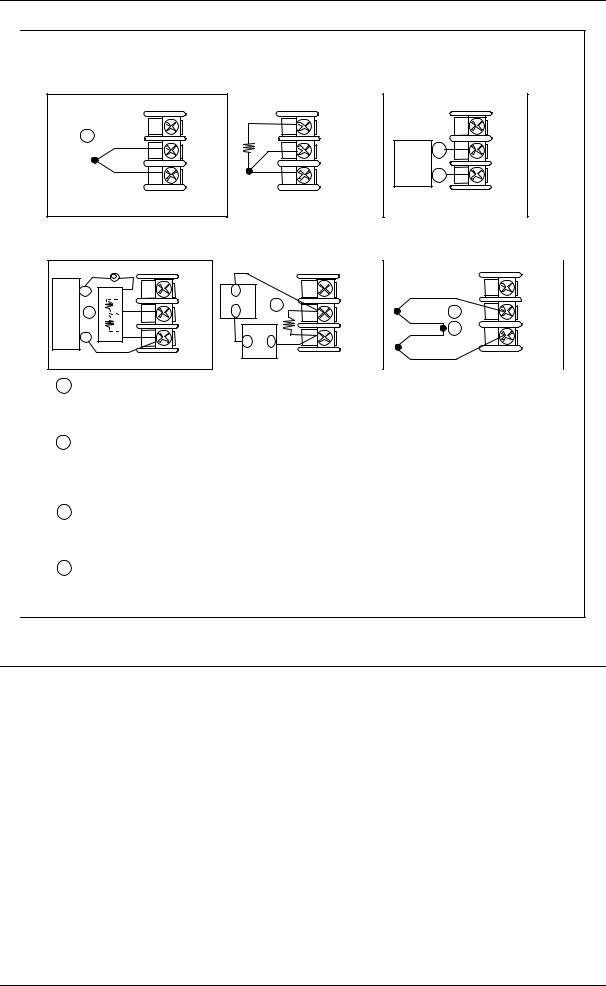
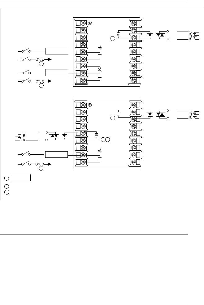
1 Alarm #2 is not available with Time Proportional Duplex or Three Position Step Control unless the Dual Relay Option is used.
2Electromechanical relays are rated at 5 Amps @ 120 Vac or 240 Vac or 30 Vdc. Customer should size fuses accordingly. Use Fast Blo fuses only.
Figure 2-8 Electromechanical Relay Output
See Table 2-5 for relay terminal connections for other Output Algorithm Types.
16 |
UDC3200 Universal Digital Controller Operator Manual |
04/08 |

|
|
|
Time Simplex |
|
|
1 |
||
|
|
|
|
|
|
19 |
Dummy Resistor |
|
|
|
|
|
|
|
|
|
|
|
|
|
L1 |
Output |
|
20 |
Relay Load |
Load |
|
|
|
Relay#1 |
|
||||
|
|
|
N.O. |
Supply |
||||
|
|
|
L2/N |
|
|
21 |
2 |
Power |
|
|
|
4 |
N.C. Alarm |
22 |
|
||
Load |
|
Relay Load |
|
|
||||
|
5 |
N.O. Relay#2 |
23 |
|
|
|||
Supply |
|
|
|
|||||
Power |
|
To terminal |
6 |
|
|
24 |
|
|
3 |
4 or 6 |
|
|
|
|
|||
|
|
|
|
|
|
|
||
|
|
7 |
|
|
25 |
|
|
|
Load |
|
Relay Load |
N.C. Alarm |
|
|
|||
|
8 |
Relay#1 |
26 |
|
|
|||
Supply |
|
To terminal |
N.O. |
|
|
|
||
Power |
|
9 |
|
|
27 |
|
|
|
3 |
7 or 9 |
|
|
|
|
|||
|
|
|
|
|
|
|
|
|
|
|
|
Time Duplex |
|
|
1 |
||
|
|
|
|
|
|
|
||
|
|
|
|
|
|
19 |
Dummy Resistor |
|
|
|
|
|
|
|
|
|
|
|
|
L1 |
Output |
|
20 |
Relay Load |
Load |
|
|
Relay#1 |
|
||||
|
1 |
|
|
N.O. |
|
Supply |
|
|
L2/N |
|
|
21 |
|
Power |
|
|
Dummy Resistor |
|
|
2 |
|||
|
|
|
|
22 |
|
||
|
|
4 |
Output |
|
|
||
Load |
Relay Load |
|
|
|
|||
|
|
|
|
|
|||
Supply |
5 |
Relay#2 |
|
23 |
|
|
|
|
N.O. |
|
|
|
|||
Power |
2 |
6 |
|
|
24 |
|
|
|
7 |
|
|
25 |
|
|
|
Load |
Relay Load |
N.C. Alarm |
|
|
|||
8 |
Relay#1 |
26 |
|
|
|||
Supply |
|
N.O. |
|
|
|
||
To terminal |
9 |
|
27 |
|
|
||
Power |
|
|
|
|
|||
7 or 9 |
|
|
|
|
|||
|
3 |
|
|
|
|
|
|
If the load current is less than the minimum rated value of 20 mA, then there may be residual voltage across both
1ends of the load even if the relay is turned off. Use a dummy resistor as shown to counteract this. The total current through the resistor and the the load must exceed 20 mA. Solid State Relays are zero-crossing type.
2 |
Solid State relays are rated at 1 Amp at 25°C and derated linearly to 0.5 Amp at 55°C. Customer should size |
fuse accordingly. Use Fast Blo fuses only. |
|
3 |
Electromechanical relays are rated at 5 Amps @ 120 Vac or 240 Vac or 30 Vdc. |
|
Customer should size fuses accordingly. Use Fast Blo fuses only. |
Figure 2-9 Solid State Relay Output
See Table 2-5 for relay terminal connections for other Output Algorithm Types.
04/08 |
UDC3200 Universal Digital Controller Operator Manual |
17 |
Time Simplex
|
|
|
|
|
19 |
|
Customer Supplied |
|
|
|
|
|
|
Electromechanical relay |
|
|
|
|
L1 |
+ |
20 |
+ |
+ |
|
|
|
L2/N |
Output #1 |
21 |
– |
|
|
|
|
1 – |
– |
|||
|
|
|
4 |
|
22 |
|
|
Load |
|
|
N.C. Alarm |
Customer Supplied |
|||
|
Relay Load |
5 |
Relay#2 |
23 |
Solid-State relay |
||
Supply |
|
To terminal |
N.O. |
|
|
||
Power |
|
6 |
|
24 |
|
|
|
|
3 |
4 or 6 |
|
|
25 |
|
|
|
|
7 |
|
|
|
||
Load |
|
Relay Load |
N.C. Alarm |
|
|
||
|
8 |
Relay#1 |
26 |
|
|
||
Supply |
|
|
N.O. |
|
|
||
|
To terminal |
|
|
|
|
||
Power |
|
9 |
|
27 |
|
|
|
3 |
7 or 9 |
|
|
|
|||
|
|
|
|
|
|
||
|
|
|
|
|
|
|
|
|
|
|
Time Duplex |
|
|
Customer Supplied |
|||
|
|
|
|
|
|
|
|
|
|
|
|
|
|
|
|
|
19 |
|
Electromechanical relay |
|
|
|
|
|
|
+ |
|
+ |
|
|
|
|
L1 |
|
|
20 |
+ |
||
|
|
|
|
Output #1 |
|
||||
|
Customer Supplied |
L2/N |
|
|
1 – |
21 |
– |
– |
|
|
|
|
|
||||||
|
Electromechanical relay |
4 |
|
|
|
22 |
Customer Supplied |
||
|
+ |
|
+ |
|
|
||||
|
+ |
5 |
|
|
23 |
Solid-State relay |
|||
|
|
Output #2 |
|
|
|||||
|
– |
– |
6 |
– |
1 |
2 |
24 |
|
|
|
Customer Supplied |
|
|
|
|
|
|||
|
|
7 |
|
|
|
25 |
|
|
|
Load |
Solid-State relay |
|
N.C. Alarm |
|
|
||||
Relay Load |
8 |
|
|
Relay#1 |
26 |
|
|
||
Supply |
|
|
N.O. |
|
|
||||
To terminal |
9 |
|
27 |
|
|
||||
Power |
|
|
|
|
|
||||
7 or 9 |
|
|
|
|
|
||||
|
|
3 |
|
|
|
|
|
|
|
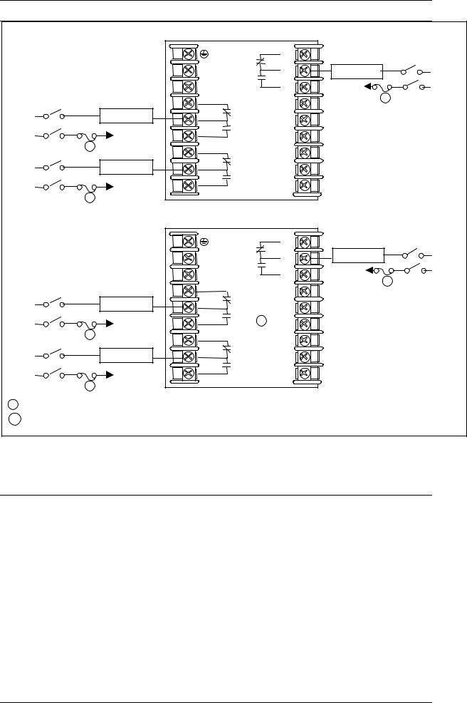
1 |
CAUTION |
Open collector outputs are internally powered at +30 Vdc. Connecting an external |
|
||||||
|
|
power supply will damage the controller. |
|
|
|
|
|
|
|
2 Alarm #2 is not available with Time Proportional Duplex or Three Position Step Control unless the Dual Relay option is used.
3Electromechanical relays are rated at 5 Amps @ 120 Vac or 240 Vac or 30 Vdc. Customer should size fuses accordingly. Use Fast Blo fuses only.
Figure 2-10 Open Collector Output
See Table 2-5 for relay terminal connections for other Output Algorithm Types.
18 |
UDC3200 Universal Digital Controller Operator Manual |
04/08 |

Time Duplex with a Dual Relay Board
|
|
|
Out Relay#2 |
|
19 |
Cool Relay Load |
Load |
|
|
|
|
N.O. |
|
||||
|
|
|
L1 Out Relay#1 |
N.O.20 |
Heat Relay Load |
Supply |
||
|
|
|
L2/N |
|
|
21 |
Power |
|
Load |
|
|
4 |
N.C. Alarm |
22 |
1 |
|
|
|
Relay Load |
5 |
23 |
|
|
|||
|
N.O. Relay#2 |
|
|
|||||
Supply |
|
To terminal |
|
|
||||
Power |
|
6 |
|
|
24 |
|
|
|
|
2 |
4 or 6 |
|
|
|
25 |
|
|
|
|
7 |
|
|
|
|
||
Load |
|
|
N.C. Alarm |
|
|
|||
|
Relay Load |
8 |
26 |
|
|
|||
Supply |
|
N.O. Relay#1 |
|
|
||||
|
To terminal |
|
|
|||||
Power |
|
9 |
|
|
27 |
|
|
|
2 |
7 or 9 |
|
|
|
|
|||
|
|
|
|
|
|
|
||
|
|
|
|
|
|
|
|
|
1Dual Electromechanical relays are rated at 2 Amps @120 Vac or 240 Vac or 30 Vdc. Customer should size fuses accordingly. Use Fast Blo fuses only.
2Electromechanical relays are rated at 5 Amps @120 Vac or 240 Vac or 30 Vdc. Customer should size fuses accordingly. Use Fast Blo fuses only.
Figure 2-11 Dual Electromechanical Relay Option Output
See Table 2-5 for relay terminal connections for other Output Algorithm Types.
|
|
|
|
|
19 |
+ |
|
|
|
|
|
|
|
|
|
|
|
|
L1 |
|
20 |
Current Output |
Controller Load |
|
|
|
L2/N |
|
21 |
4–20 mA |
0-1000 ohms |
|
|
|
|
– |
|
||
|
|
|
4 |
|
22 |
|
|
Load |
|
Relay Load |
N.C. Alarm |
|
|
||
|
5 |
23 |
|
|
|||
|
N.O. Relay#2 |
|
|
||||
Supply |
|
To terminal |
|
|
|||
Power |
|
6 |
|
24 |
|
|
|
2 |
4 or 6 |
|
|
|
|||
|
|
|
|
|
|
||
|
|
7 |
|
25 |
|
|
|
Load |
|
Relay Load |
N.C. Alarm |
|
|
||
|
8 |
Relay#1 |
26 |
|
|
||
Supply |
|
|
N.O. 1 |
|
|
||
|
To terminal |
|
|
|
|
||
Power |
|
9 |
|
27 |
|
|
|
2 |
7 or 9 |
|
|
|
|||
|
|
|
|
|
|
||
|
|
|
|
|
|
|
1When the instrument has the Current Output as shown, no Alarms are available when using the Time Proportional Duplex or Three Position Step Control Output Algorithms, as these outputs require both available relays.
2Electromechanical relays are rated at 5 Amps @120 Vac or 240 Vac or 30 Vdc Customer should size fuses accordingly. Use Fast Blo fuses only.
Figure 2-12 Current Output
See Table 2-5 for relay terminal connections for other Output Algorithm Types.
04/08 |
UDC3200 Universal Digital Controller Operator Manual |
19 |
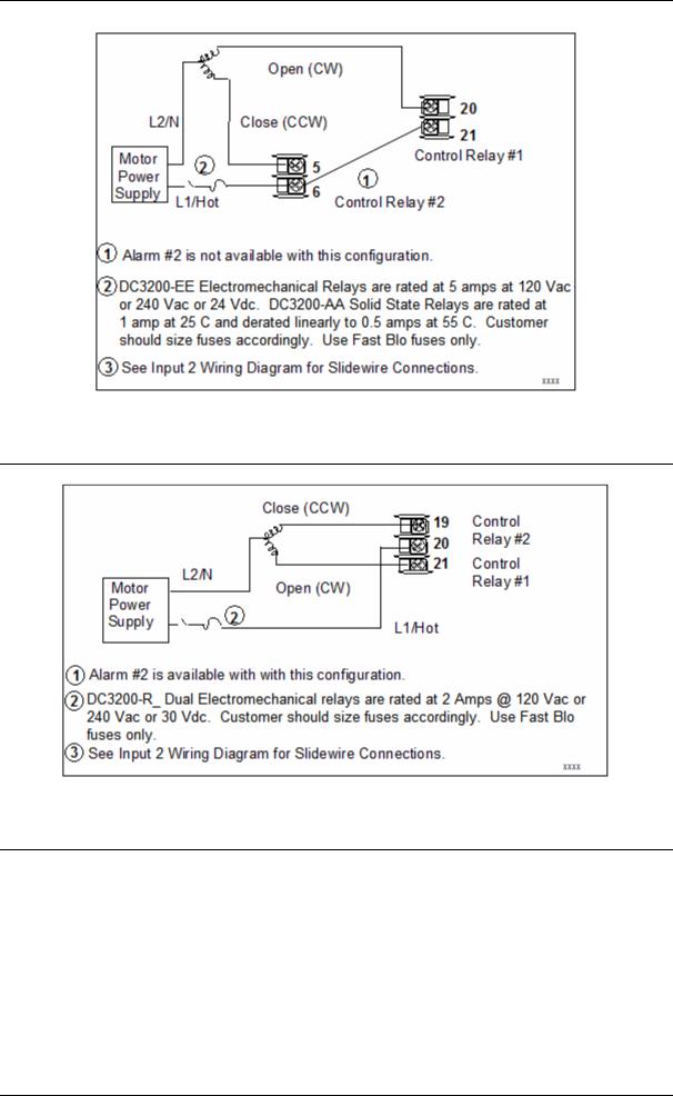
Figure 2-13 Position Proportional or Three Position Step Control Connection, Models DC3200-EE or DC3200-AA
Figure 2-14 Position Proportional or Three Position Step Control Connections, Model DC3200-R_
20 |
UDC3200 Universal Digital Controller Operator Manual |
04/08 |
COMMUNICATION MASTER
D+ (B) SHLD D– (A)
1 2
16 SHLD |
SHLD |
17 D+ (B) |
D+ |
18 D– (A) |
D– |
120 OHMS
|
|
|
|
Connect shield |
TO OTHER |
|
|
to ground at one |
|
COMMUNICATION |
|
|
end only. |
|
CONTROLLERS |
|
|
|
|
D– |
D+ |
|
|
|
120 OHMS ON LAST LEG
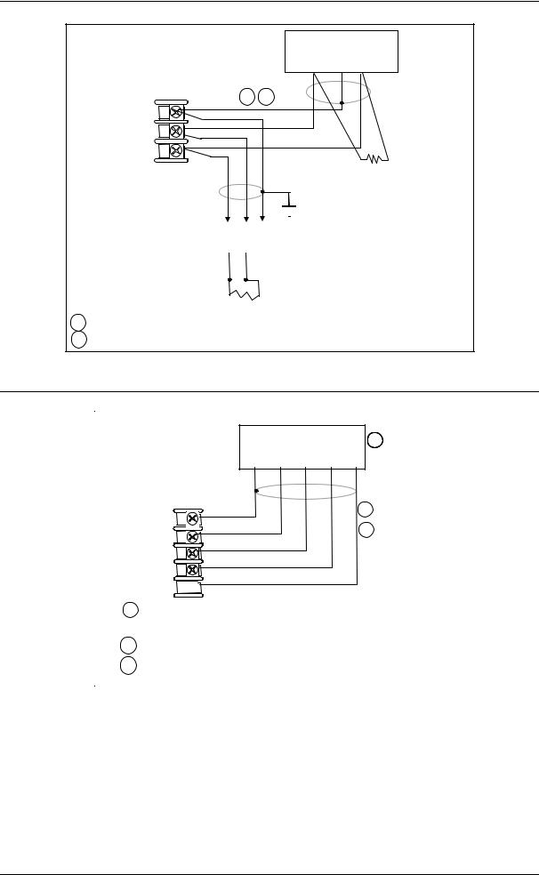
1 Do not run the communications lines in the same conduit as AC power. 2 Use shielded twisted pair cables (Belden 9271 Twinax or equivalent).
Figure 2-15 RS-422/485 Communications Option Connections
COMMUNICATION MASTER |
3 |
OR SWITCH |
SHLD TXDR –+ TXD+R - TRXD+– TRXD-+
1
1414SHLDSHLD
2
1515RXDRXD+
16 RXD –
16 RXD-
1717TXDTXD+
1818TXDTXD–-
1Do not run the communications lines in the same conduit as AC power. Correct connections may require the use of an Ethernet cross-over cable.
2Use Shielded twisted-pair, Category 5 (STP CAT5) Ethernet cable.
3Use Switch rather than Hub to maximize performance.
Figure 2-16 Ethernet Communications Option Connections
Figure 2-16 and Table 2-6 shows how to connect a UDC to a MDI Compliant Hub or Switch utilizing a straight-through cable or for connecting a UDC to a PC utilizing a crossover cable.
04/08 |
UDC3200 Universal Digital Controller Operator Manual |
21 |
Loading...