


TP970-72, TP970-74, TP9600, and TP9630
Pneumatic Sensors, Humidistats,
and Thermostats |
|
INSTALLATION INSTRUCTIONS |
|
|
Contents |
INTRODUCTION ............................................................................................................................ |
2 |
BEFORE INSTALLATION ............................................................................................................................ |
2 |
Tools and Accessories ........................................................................................ |
2 |
General ............................................................................................................... |
2 |
Dimensions ......................................................................................................... |
4 |
Covers ................................................................................................................ |
5 |
General ............................................................................................................... |
5 |
Removing and Replacing Covers ....................................................................... |
6 |
Installing Cover Inserts ....................................................................................... |
7 |
Painting (Beige Plastic Covers Only) .................................................................. |
7 |
INSTALLATION ............................................................................................................................ |
9 |
Installation with Recessed Tubing ...................................................................... |
9 |
Hollow-Core Studded Wall ................................................................................. |
9 |
Block or Brick Wall ............................................................................................ |
28 |
Concrete Pour .................................................................................................. |
34 |
Mullion .............................................................................................................. |
38 |
Installation with Surface-Mounted Tubing ........................................................ |
40 |
Piping ................................................................................................................ |
45 |
CALIBRATION .......................................................................................................................... |
45 |
Tools Required ................................................................................................. |
45 |
Humidistat/Humidity Sensor ............................................................................. |
45 |
General ............................................................................................................. |
45 |
Setpoint Lock .................................................................................................... |
46 |
Throttling Range Adjustment (HP970 and HP972) ........................................... |
46 |
Calibration Check ............................................................................................. |
46 |
Recalibration .................................................................................................... |
46 |
Thermostat/Temperature Sensor ...................................................................... |
47 |
General ............................................................................................................. |
47 |
Throttling Range Adjustment ............................................................................ |
47 |
Calibration Check ............................................................................................. |
47 |
Recalibration .................................................................................................... |
47 |
APPENDIX: BACKPLATES .......................................................................................................................... |
48 |
General ............................................................................................................. |
48 |
Removing Stat from Conventional Backplate ................................................... |
48 |
Removing Stat from Quick-Mount Backplate.................................................... |
48 |
® U.S. Registered Trademark |
|
Copyright © 1998 Honeywell Inc. • All Rights Reserved |
95-5597-1 |
TP970-72, TP970-74, TP9600, AND PNEUMATIC SENSORS, HUMIDISTATS, AND THERMOSTATS
INTRODUCTION
The BEFORE INSTALLATION section shows tools and accessories used during installation and calibration, dimensions of major accessories, and procedures for preparing thermostat and humidistat covers. The INSTALLATION section shows how to install thermostats, humidistats, sensors, and fittings and shows connections for oneand two-pipe applications. The CALIBRATION section describes calibration and adjustment procedures.
For information on how to remove a stat body from a stat backplate, refer to APPENDIX: BACKPLATES.
BEFORE INSTALLATION
Tools and Accessories
General
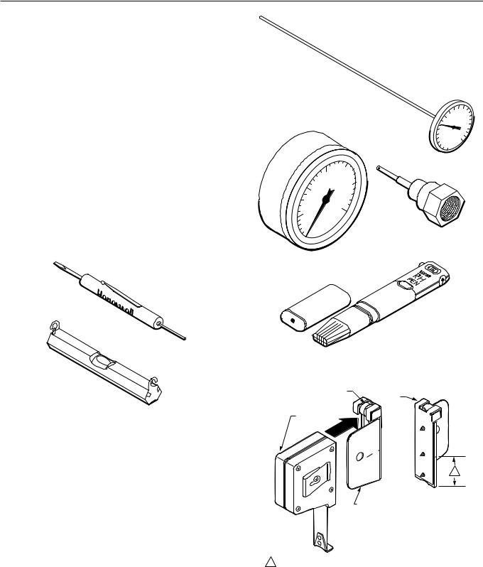
Figure 1 shows tools used for stat installation. Figure 2 shows tools used during calibration check. Figures 3 through 8 show accessories used for several mounting methods.
THERMOSTAT TOOL
POCKET LEVEL CCT348
C3150-1
Fig. 1. Installation Tools Used for All Mounting Methods.
TEST THERMOMETER |
|
100 |
120140 |
|
CCT902 |
|
160 |
||
80 |
||||
|
180 |
|||
|
60 |
|
||
|
|
200 |
||
|
40 |
|
||
|
|
220 |
||
|
20 |
|
||
|
0 |
|
||
20
15
25
10
30
5
0
GAGE 305965
0-30 PSI (0-207 kPa)
GAGE PORT NEEDLE (CCT729A CAN BE USED TO
CONNECT TO 5/32 IN. AND 1/4 IN. POLYETHYLENE TUBING)
DIGITAL RELATIVE
HUMIDITY INDICATOR
PEN CCT915
C3928
Fig. 2. Calibration Tools.
LEVEL |
BACK |
|
VIEW |
TAPE
MEASURE
C
L
1
THERMOSTAT
MOUNTING
GUIDE TOOL
11—1/2 IN. (38 MM) FROM BOTTOM OF TAPE MEASURE TO CENTER MARK CORRESPONDING TO CENTER OF STAT.
C3151
Fig. 3. Tape Measure CCT422 and Thermostat
Mounting Guide Tool CCT690.
95-5597—1 |
2 |
TP970-72, TP970-74, TP9600, AND TP9630 PNEUMATIC SENSORS, HUMIDISTATS, AND THERMOSTATS
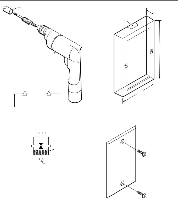
PROTECTIVE SLEEVE FOR BORE
REPLACEMENT PROTECTIVE SLEEVES
ARE AVAILABLE. ORDER CCT691A.
 THERMOSTAT STEP/BORING TOOL
CORDLESS DRILL
! WARNING |
! |
TO AVOID BODILY INJURY AND PROTECT |
|
BORE, LEAVE PROTECTIVE SLEEVE ON |
|
STEP/BORING TOOL EXCEPT WHEN |
|
DRILLING WITH BORE. |
C3152 |
Fig. 4. Thermostat Step/Boring Tool CCT691
and Cordless Drill CCT713.
SEE CHART FOR BARB SIZE
A B
|
|
|
|
|
|
|
|
FILTER |
|
|
|
|
|
|
|
|
|
|
|
|
|
|
|
|
|
INLET |
|
|
|
|
|
|
|
|
|
|
|
||
|
|
|
|
|
|
|
ALL INLET BARBS |
|
|
|
|
|
|
|
|
|
1/4 IN. (6 MM) |
|
|
|
REMOTE RESTRICTORS |
|
|||||||
|
|
|
|
|
|
|
|
|
|
|
|
|
|
|
|
|
|
BARB SIZE |
|
PART NO. |
ORIFICE |
|
BODY |
IN INCHES (MM) |
|||||
14002913– |
SIZE IN INCHES |
|
COLOR |
A |
B |
||||
|
|
|
|
|
|
|
|
|
|
–001* |
0.005 |
|
|
|
|
|
Blue |
1/4 (6) |
5/32 (4) |
|
|
|
|
|
|
|
|
|
|
–004 |
0.005 |
|
|
|
|
|
Blue |
5/32 (4) |
5/32 (4) |
|
|
|
|
|
|
|
|
|
|
* ONE BARB CAP 14003567-001 FURNISHED WITH RESTRICTOR
C3931-1
Fig. 5. Remote Restrictors Used for Piping.
1/2
(13)
REMOVABLE WEB (CUT AWAY WITH POCKET KNIFE)
3-17/32
(90)
2-5/16
(59)
C3153
Fig. 6. Wall Mounting Ring 14004458-001 for Flush or Surface Mounting to Brick or Block Wall or to Wall with Surface-Mounted Tubing.
NOTE: USE FOR APPLICATION WITH RECESSED TUBING WHEN STAT IS TO BE MOUNTED AT A LATER DATE
C3154
Fig. 7. Wall Plate Bag Assembly 14001905-001.
3 |
95-5597—1 |

TP970-72, TP970-74, TP9600, AND PNEUMATIC SENSORS, HUMIDISTATS, AND THERMOSTATS
Dimensions
Figures 9 through 13 show dimensions of major installation accessories.
4-5/8
(117)
2-3/4 (70) 

C5532
Fig. 7A. Wall Plate Bag Assembly 14002136-004.
TWIN TUBE
AK3240 (5/32 IN. O.D. X 0.030 IN. WALL) OR
AK3241 (1/4 IN. O.D. X 0.040 IN. WALL)
BUNDLED TUBING AK3168 (5/32 IN. O.D. X 0.030 IN. WALL)
C3155
Fig. 8. Twin Tube AK3240 (5/32 in. O.D. x 0.030 in. wall) or AK3241 (1/4 in. O.D. x 0.040 in. wall) and Bundled Tubing AK3168 (5/32 in. O.D. x 0.030 in. wall).
4-1/2
(115)
2-7/8
(73)
|
2-1/4 |
|
(57) |
1-11/16 |
|
(43) |
|
NO. 6-32 X 1/2 IN. |
|
MOUNTING SCREW (2) |
|
PROVIDED WITH |
C3180 |
SHALLOW WALLPLATE |
Fig. 9. Shallow Wall Plate 14001614-001
Dimensions in Inches (Millimeters).
KNOCKOUT FOR 1/2 IN. CONDUIT OR
FITTING SNAP RING (BOTH SIDES,
BACK, TOP AND BOTTOM)
3/16 (5) |
TAPPED HOLE (2) 6 x 32 |
|||
(6 PLACES) |
MOUNTING SCREWS |
|||
|
|
|
6 x 32 - 1/2 (PROVIDED) |
|
TAPPED HOLE |
ALIGNMENT |
|||
8 x 32 (2 PLACES) |
FOR FINISHED WALL |
|||
|
|
|
1/4 (6) |
|
GUIDES FOR |
1/2 (13) |
|||
|
||||
MOUNTING |
3/4 (19) |
|||
BRACKET |
||||
|
||||
|
|
|
|
|
2-5/8
(67)
2-9/16 (65) |
1-7/16 |
(37)
C3930
Fig. 10. Deep Wall Box 14001355-001
Dimensions in Inches (Millimeters).
95-5597—1 |
4 |
TP970-72, TP970-74, TP9600, AND TP9630 PNEUMATIC SENSORS, HUMIDISTATS, AND THERMOSTATS
1 IN. (25 MM) OFFSET FOR BOX
2 IN. (51 MM) OFFSET FOR BOX
1-1/2
(38)
 3-1/16 (78)
 1-7/16 (37)
C3179
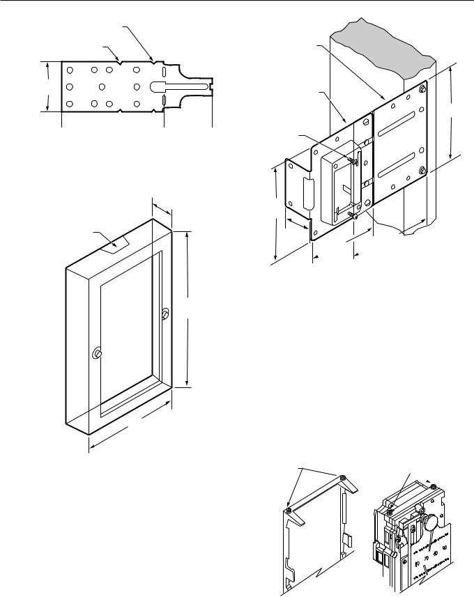
Fig. 11. Deep Wall Box Mounting Bracket 14001354-001
Dimensions in Inches (Millimeters).
1/2
(13)
REMOVABLE WEB (CUT AWAY WITH POCKET KNIFE)
3-17/32
(90)
2-5/16
(59)
C3153
Fig. 12. Wall Mounting Ring 14004458-001
Dimensions in Inches (Millimeters).
EXTENSION
PLATE
STUD-MOUNTED STAT PLATE (ALIGN OVER ELECTRICAL BOX)
NO. 6-32 X 1/2 IN.
MOUNTING SCREW (2)
PROVIDED WITH
STUD-MOUNTED
STAT PLATE
3-15/16
(100)
1-1/16
(27)
3-1/16  (78)
(78)
3-15/16
(100)
3-9/16  (91)
(91)
C3933
Fig. 13. Stud-Mounted Stat Plate 14004610-001
and Extension Plate 14004656-001
Dimensions in Inches (Millimeters).
Covers
General
This section shows how to remove and replace thermostat and humidistat covers and how to install Inserts over the setpoint and DAY/AUTO slots at the bottom of covers. This section also lists recommended paints for covers that can be painted and describes painting procedures.
Cover assembly and disassembly differs between conventional and Quick-Mount stats. On a conventional stat the cover mounts to setscrews in the backplate, while on a Quick-Mount stat the cover mounts to setscrews in the stat body (Fig. 14).
CONVENTIONAL STAT
SETSCREWS QUICK-MOUNT STAT  SETSCREWS
STAT BACKPLATE |
STAT BODY |
|
C3569 |
Fig. 14. Setscrew Locations for Conventional and Quick-Mount Stats.
5 |
95-5597—1 |
TP970-72, TP970-74, TP9600, AND PNEUMATIC SENSORS, HUMIDISTATS, AND THERMOSTATS
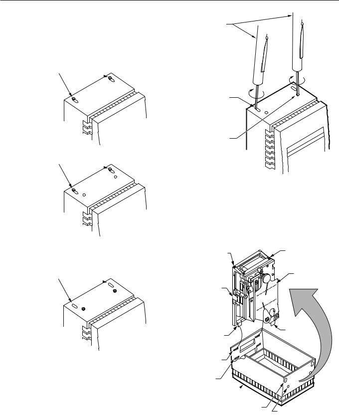
To determine the cover mounting method, look at the holes at
the top of the cover (Fig. 15). If the setscrews are raised
THERMOSTAT TOOL
against the back pair of slots (toward the wall), the setscrews are in the backplate and the stat is a conventional stat. If the setscrews are raised into the front pair of holes, the setscrews are in the stat body and the stat is a Quick-Mount stat.
CONVENTIONAL STAT
SETSCREWS VISIBLE 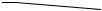
CONVENTIONAL STAT
SETSCREW SLOT (2)
SPECIAL COVER
QUICK-MOUNT STAT
SETSCREW HOLE (2)
COVER 
SETSCREWS VISIBLE 
90 80 70
60 Honeywell
C3158
STANDARD COVER
Fig. 16. Removing Cover.
Use the following procedure to replace a cover:
1.Hook slots at bottom of cover over two bottom tabs of stat (Fig. 17). Setpoint adjustment will align with setpoint slot.
QUICK-MOUNT STAT
SETSCREWS VISIBLE 
STANDARD COVER
C3157
Fig. 15. Conventional and Quick-Mount Stats.
Removing and Replacing Covers
Cover assembly/disassembly requires Thermostat Tool CCT735A (MQT735A). Use the following procedure to remove a cover:
1.Locate setscrews in cover (back pair of slots for conven tional stat, front pair of holes for Quick-Mount stat).
2.Place Allen wrench end of Thermostat Tool through slot/ hole and into setscrew (Fig. 16).
3.Rotate Thermostat Tool clockwise until setscrew no longer touches cover. Repeat for other setscrew.
4.Pull Cover out and down.
CONVENTIONAL STAT
SETSCREW LOCATION (2)  QUICK-MOUNT STAT SETSCREW LOCATION (2)
STAT
STAT
BACKPLATE
|
90 |
|
80 |
|
70 |
|
60 |
CONVENTIONAL |
QUICK-MOUNT |
STAT TAB (2) |
STAT TAB (2) |
CONVENTIONAL STAT
MOUNTING SLOT (2)
QUICK-MOUNT STAT
MOUNTING SLOT (2)
COVER
CONVENTIONAL STAT
SETSCREW SLOT (2)
QUICK-MOUNT STAT
SETSCREW HOLE (2)
C4110
Fig. 17. Replacing Cover.
95-5597—1 |
6 |

TP970-72, TP970-74, TP9600, AND TP9630 PNEUMATIC SENSORS, HUMIDISTATS, AND THERMOSTATS
2.Swing cover up and over stat.
3.Place Allen wrench end of Thermostat Tool through setscrew slot and into setscrew.
4.Rotate Thermostat Tool counterclockwise until setscrew holds cover securely onto stat backplate (conventional stat) or stat body (Quick-Mount stat). Repeat for other setscrew.
Installing Cover Inserts
The following Cover Inserts are available for the setpoint and DAY/AUTO lever slots on stat covers:
|
|
|
|
|
|
|
|
Applicable |
|
Part No. |
Finish |
Covers |
Slot |
|
|
|
|
|
|
14004437 |
-001 |
Satin |
14004406-XXX |
DAY/AUTO |
|
|
Chrome |
Standard Covers* |
|
|
|
|
|
|
|
-002 |
Beige |
14004407-XXX |
|
|
|
Plastic |
Standard Covers* |
|
|
|
|
|
|
14004438 |
-001 |
Satin |
14004406-XXX |
Setpoint |
|
|
Chrome |
Standard Covers* |
|
|
|
|
|
|
|
-002 |
Beige |
14004407-XXX |
|
|
|
Plastic |
Standard Covers* |
|
|
|
|
|
|
14004442 |
-001 |
Black |
14002132-XXX |
DAY/AUTO |
|
|
|
Special Covers† |
Setpoint |
|
|
|
|
|
*See HP970 and TP970 Series Standard Covers and Accessories Specification Data 77-1003.
†See HP970 and TP970 Series Standard Covers Specification Data 77-9828.
Cover Inserts are removable. Covers ship with setpoint and DAY/AUTO lever slots “open” (without Insert) or “closed” (with Insert present) as follows:
—Setpoint slot: Open or closed as ordered (see HP970 and TP970 Series Standard Covers and Accessories Specification Data 77-1003 and HP970 and TP970 Series Special Covers and Accessories Specification Data 77-9828)
—DAY/AUTO lever slot:
•No Insert on vertical stat covers
•Insert present on horizontal stat covers
Figures 18 and 19 show how to install Inserts.
COVER
UNUSED
SLOT
SLOT
COVER
INSERT
M10828
Fig. 18. Installing DAY/AUTO Cover Insert
14004437-001/-002.
 COVER
COVER
|
SETPOINT |
|
SLOT |
SETPOINT |
|
COVER |
M10827 |
INSERT |
Fig. 19. Installing Setpoint Cover Insert
14004438-001/-002.
Painting (Beige Plastic Covers Only)
Beige Plastic Covers can be painted with recommended paints before or after Covers are installed.
Recommended Paints
If a non-latex paint is required, use Rust-Oleum Enamel (a fish-oil type enamel). No primer is needed.
If a latex paint is required, use one of the following as a primer and follow with any latex wall paint:
—Sears Anti-Rust Enamel (a soya-alkyd type enamel in a spray can)
—True Value Tru-Test X-O Stain Primer/Sealer Stain Killer XOS-1 White (a white-pigmented, shellac type primer)
Painting Procedures
Painting Cover before Window is Installed
Order the following equipment:
—Cover Assembly 14004402-002
—DAY/AUTO Cover Insert 14004437-002 (optional)
—Setpoint Cover Insert 14004438-002 (optional)
—Window 14004405-XXX according to the following table:
1.Remove or add Inserts to Cover Assembly as required (see INSTALLING COVER INSERTS).
2.Wash Cover Assembly with mild dish detergent solution.
3.Dry with paper towel.
4.Paint with approved paint.
5.Allow to dry.
6.When Window has been assembled to Cover, disassembly may damage Window. Before installing Window, note the following:
a.Check that Window display is correct for job requirements.
b.Check Window orientation to cover. Cover setpoint and DAY/AUTO lever slots should be on the bottom (vertical mounting) or to the right (horizontal mounting).
7.Remove liner from adhesive on back of Window. Slide Window into Cover opening (Fig. 20) and press in place.
7 |
95-5597—1 |

TP970-72, TP970-74, TP9600, AND PNEUMATIC SENSORS, HUMIDISTATS, AND THERMOSTATS
90 80
70
60
90 80
70
60
COVER
WINDOW CURVED FOR INSTALLATION
C3156
Painting Cover after Window is Installed
Order the following equipment:
—Cover Assembly 14004407-XXX (select from HP970 and TP970 Series Standard Covers and Accessories Spec Data 77-1003)
—Paint Mask 14002193-001
—DAY/AUTO Cover Insert 14004437-002 (optional)
—Setpoint Cover Insert 14004438-002 (optional)
1.Remove or add Inserts to Cover Assembly as required (see INSTALLING COVER INSERTS).
2.Wash Cover Assembly with mild dish detergent solution. Do not immerse.
3.Dry with paper towel.
4.Apply Paint Mask to window. Trim around window as needed.
5.Paint with approved paint.
6.Allow to dry.
7.Remove Paint Mask.
Fig. 20. Installing Window.
|
|
|
|
|
|
|
|
|
Window 14004405-XXX |
|
Stat |
|
|
|
|
||
Silver |
Beige |
Orientation |
Honeywell |
Display (Unit) |
|
|||
Background |
Background |
Vert. |
|
Horiz. |
Logo |
Setpoint |
|
Thermometer |
-001 |
-101 |
X |
|
|
X |
None |
|
None |
|
|
|
|
|
|
|
|
|
-002 |
-102 |
|
|
X |
X |
None |
|
None |
-003 |
-112 |
X |
|
X |
|
None |
|
None |
-004 |
-113 |
X |
|
|
|
60-90 (F) |
|
60-90 (F) |
|
|
|
|
|
|
|
|
|
-005 |
-103 |
X |
|
|
X |
60-90 (F) |
|
60-90 (F) |
-006 |
N/A |
X |
|
|
X |
40-70 (F) |
|
40-70 (F) |
-007 |
-104 |
X |
|
|
X |
15-30 (C) |
|
15-30 (C) |
|
|
|
|
|
|
|
|
|
-008 |
-106 |
X |
|
|
X |
60-90 (F) |
|
None |
-009 |
N/A |
X |
|
|
X |
40-70 (F) |
|
None |
-010 |
N/A |
X |
|
|
X |
15-30 (C) |
|
None |
|
|
|
|
|
|
|
|
|
-011 |
N/A |
X |
|
|
X |
None |
|
60-90 (F) |
-012 |
N/A |
X |
|
|
X |
None |
|
15-30 (C) |
-013 |
N/A |
|
|
X |
|
60-90 (F) |
|
60-90 (F) |
|
|
|
|
|
|
|
|
|
-014 |
N/A |
|
|
X |
X |
60-90 (F) |
|
60-90 (F) |
-015 |
-105 |
|
|
X |
X |
15-30 (C) |
|
15-30 (C) |
-016 |
-107 |
X |
|
|
X |
20-80 (% rh) |
|
None |
|
|
|
|
|
|
|
|
|
-017 |
N/A |
|
|
X |
X |
20-80 (% rh) |
|
None |
-018 |
N/A |
X |
|
|
X |
COOLER/WARMER |
|
None |
-019 |
N/A |
X |
|
|
X |
HEAT RANGE/COOL RANGE |
|
60-90 (F) |
|
|
|
|
|
|
60-90 (F) |
|
|
N/A |
-110 |
X |
|
|
X |
15-30 (C) |
|
60-90 (F) |
-021 |
N/A |
|
|
X |
X |
40-70 (F) |
|
40-70 (F) |
|
|
|
|
|
|
|
|
|
95-5597—1 |
8 |

TP970-72, TP970-74, TP9600, AND TP9630 PNEUMATIC SENSORS, HUMIDISTATS, AND THERMOSTATS
INSTALLATION
This section categorizes stat installation according to the following factors:
—Location of tubing: recessed or surface-mounted
—Type of wall: hollow-core studded, block or brick, concrete, or mullion
—Condition of wall: rough-in or finished
Installation with Recessed Tubing
Examples of installations with recessed tubing include: hollow-core stud walls, block or brick walls, concrete walls, and mullions.
Hollow-Core Studded Wall
A hollow-core studded wall requires either rough-in mounting or finished-wall installation.
Rough-In Installation
Rough-in installation is done to a stud before the wall is drywalled or to lath before the wall is plastered.
NOTE: If the wall is already drywalled or plastered, see FINISHED WALL INSTALLATION.
Mounting to Stud with Stud-Mounted Stat Plate
Mounting to a stud using a Stud-Mounted Stat Plate requires the following equipment:
—Stud-Mounted Stat Plate 14004610-001 (Fig. 21)
—Extension Plate 14004656-001 (optional) (Fig. 21)
—Tape Measure CCT422
—No. 8 sheet metal screws
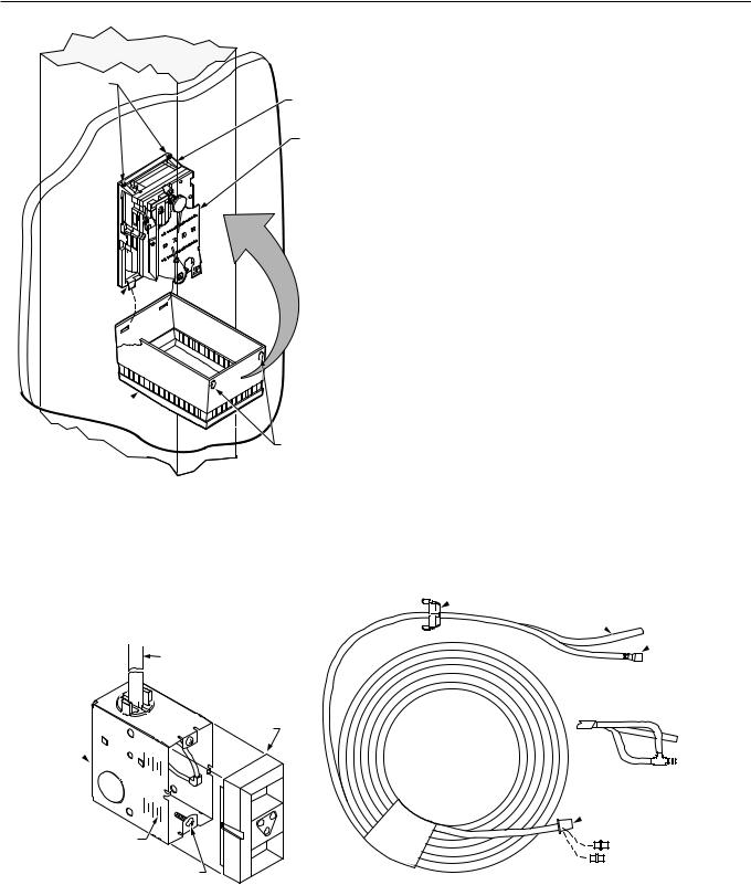
—Cordless Drill CCT713 (Fig. 22)
—TEK Drill Adapter Screwdriver CCT240 (Fig. 22)
—No. 8 x 1/2 in. TEK Screws CCT2444 (two per stat)
—Stud Mount Box Clip CCT2642 for mounting StudMounted Stat Plate to metal stud (Fig. 23) (optional)
—Thermostat Tool CCT735A (MQT735A)
SCREWS |
|
|
PROVIDED |
|
|
STUD-MOUNTED |
EXTENSION PLATE |
|
STAT PLATE |
|
|
NOTE: MAXIMUM EXTENSION IS 2-3/4 IN. (70 MM) USING |
C3932 |
|
ONE PLATE, 5-3/8 IN. (137MM) USING TWO PLATES. |
||
Fig. 21. Stud-Mounted Stat Plate and
Optional Extension Plate.
 TEK DRILL ADAPTER
SCREWDRIVER
CORDLESS DRILL
C3167
Fig. 22. TEK Drill Adapter Screwdriver and Cordless Drill.
C3181
Fig. 23. Stud Mount Box Clip.
TAPE
MEASURE
C3162
1. Measure and mark approximate stat location on stud.
9 |
95-5597—1 |
TP970-72, TP970-74, TP9600, AND PNEUMATIC SENSORS, HUMIDISTATS, AND THERMOSTATS
HORIZONTAL MOUNTING TO HORIZONTAL STUD
HORIZONTAL MOUNTING TO VERTICAL STUD
OR VERTICAL MOUNTING TO HORIZONTAL STUD
 OR
OR
VERTICAL MOUNTING TO VERTICAL STUD
TEK SCREW (2)
EXTENSION PLATE
SHEET METAL SCREW (2)
EXTENSION PLATE
BUTTON (2)
STUD-MOUNTED
STAT PLATE 
STUD MOUNT
BOX CLIP
MOUNTING TO METAL STUD
(REQUIRES STUD MOUNT BOX CLIP CCT2642)
NOTE:
TO ATTACH STUD-MOUNTED STAT PLATE TO EXTENSION PLATE:
A.FIT TWO BUTTONS ON EXTENSION PLATE INTO SLOTS ON STUD-MOUNTED STAT PLATE.
B.ALIGN TWO OUTER HOLES AND/OR SINGLE CENTER HOLES ON TWO PLATES.
C.FASTEN PLATES TOGETHER WITH NO. 8 x 1/2 IN. SHEET METAL SCREWS.
D.FASTEN EXTENSION PLATE TO STUD USING NO. 8 x 1/2 IN. TEK SCREWS.
C3937
TYPICAL MOUNTING WITH EXTENSION PLATE
2.Attach Stud-Mounted Stat Plate, using Extension Plate if required to center stat over electrical box. Use Cordless Drill and TEK Screwdriver Drill Adapter to drive No. 8 x 1/2 in. TEK screws, or use Stud Mount Box Clip as required.
95-5597—1 |
10 |

TP970-72, TP970-74, TP9600, AND TP9630 PNEUMATIC SENSORS, HUMIDISTATS, AND THERMOSTATS
TUBING
STUD-MOUNTED
STAT PLATE
 TAB
TAB
C3934
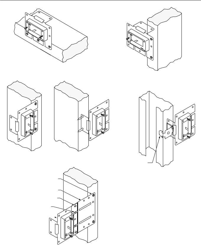
3.Fish tubing through Stud-Mounted Stat Plate. Anchor tubing in upper-right or lower-left corner of Plate by crimping Plate tab with pliers.
TUBING
 STAT
STAT
BACKPLATE
C3935
4.After drywall or plaster is up, release tubing from corner of Plate. Connect tubing to barbs on stat backplate.
STUD MOUNTED
STAT PLATE
 STAT
STAT
BACKPLATE
C3936
5.Hook keyhole slots of stat backplate over backed-out screws on Stud-Mounted Stat Plate. Level stat backplate and tighten screws.
STAT
BACKPLATE
STAT
C3573
6. Mount stat to stat backplate.
11 |
95-5597—1 |
TP970-72, TP970-74, TP9600, AND PNEUMATIC SENSORS, HUMIDISTATS, AND THERMOSTATS
SETSCREWS
STAT
BACKPLATE
STAT
TAB (2) 
COVER
SETSCREW
SLOTS
C4116
7.Hook slots on stat cover over bottom tabs on stat backplate. Swing stat cover up and over stat. Use Thermostat Tool to raise stat backplate setscrews into setscrew slots on top of cover.

 PROTECTOR CAP
PLASTIC CABLE
ASSEMBLY 8 FT (2.5 M)
 BUSHING
FITTING
FINDER
DEEP WALL
BOX 
ALIGNMENT GUIDE
FOR FINISHED WALL
NO. 6–32 X 1/2 IN. SCREW (2)
PROVIDED WITH DEEP WALL BOX
Mounting to Stud with Deep Wall Box
Mounting to a stud using a Deep Wall Box requires the following equipment:
—Deep Wall Box Assembly 14001492-001 (includes two pipe plastic cable assembly, see Fig. 24) or separate parts for oneand three-pipe applications as follows:
•Deep Wall Box 14001355-001
•Fitting Finder 14000706-001 (optional)
•One of the following:
14001491-001 one-pipe or -003 three-pipe Plastic Cable Assembly
or
14001494-001 one-pipe, -002 two-pipe, or -003 three-pipe Copper Cable Assembly
—Barb Couplings CCT1606B (MJP1606B) (5/32 x 1/4 in.) or CCT1628B (MJP1628B) (5/32 x 5/32 in.) for plastic tubing (one, two, or three Couplings required according to application)
—Tape Measure CCT422
—Cordless Drill CCT713 (Fig. 25)
—TEK Drill Adapter Screwdriver CCT240 (Fig. 25)
—The following items according to mounting method:
•Directly to stud:
Two No. 8 x 2 in. Pan Head Sheet Metal Screws CCT2310 (MVH2310)
or
Two 6d 2 in. (51 mm) nails
•Between two studs:
Universal Strap CCT2630 (MVP2630) (Fig. 26) Two No. 8 x 1/2 in. TEK Screws CCT2444
One No. 8-32 x 1/2 in. Round Head Screw CCT2410
•Offset from stud (e.g., to center over electrical box): Deep Wall Box Mounting Bracket 14001354-001 One No. 8-32 x 1/4 in. Round Head Screw CCT2408 Two No. 8 x 1/2 in. TEK Screws CCT2444
—Thermostat Tool CCT735A (MQT735A)


 BUSHING
MAIN
 BARB CAP
BRANCH
ONE-PIPE ASSEMBLY
SWITCH
MAIN
BRANCH |
BARB TEE |
THREE - PIPE ASSEMBLY
 PROTECTOR CAP
BARB
COUPLINGS
FOR PLASTIC
TUBING C3562
CABLE ASSEMBLY
Fig. 24. Deep Wall Box Assembly and Cable Assemblies.
95-5597—1 |
12 |
TP970-72, TP970-74, TP9600, AND TP9630 PNEUMATIC SENSORS, HUMIDISTATS, AND THERMOSTATS
 TEK DRILL ADAPTER
SCREWDRIVER
CORDLESS DRILL
C3167
DEEP WALL BOX
MOUNTING
BRACKET
 NO. 8–32 X 1/4 IN.
SCREW
NO. 6–32 X 1/2 IN.
SCREW (2) PROVIDED
 DEEP WALL BOX
NO. 8–32 X 1/4 IN.
SCREW
Fig. 25. TEK Drill Adapter Screwdriver and Cordless Drill.
1 (25) |
3/4 (19) |
|
NO. 8–32 |
||
|
 24 (610)
C3161
Fig. 26. Universal Strap.
MOUNTING
BRACKET
C3566
2.If offset from stud is required (e.g., to center stat over electrical box), attach Deep Wall Box to Deep Wall Box Mounting Bracket with No. 8-32 x 1/4 in. Round Head Screw.
TAPE
MEASURE
C3162
1. Measure and mark approximate stat location on stud.
13 |
95-5597—1 |

TP970-72, TP970-74, TP9600, AND PNEUMATIC SENSORS, HUMIDISTATS, AND THERMOSTATS
STUD
CABLE
ASSEMBLY
 DEEP WALL BOX
NO. 8 x 2 IN.
SHEET METAL SCREWS
OR 6d 2 IN. (51 MM) NAILS
MOUNTING DEEP WALL BOX DIRECTLY TO STUD
NO. 8 x 1/2 IN. TEK SCREW
UNIVERSAL STRAP
DEEP WALL BOX
8-32 x 1/2 IN. ROUND HEAD SCREW (INSTALL FROM INSIDE BOX)
NO. 8 x 1/2 IN.
TEK SCREW
MOUNTING DEEP WALL BOX BETWEEN STUDS
USING UNIVERSAL STRAP
DEEP WALL BOX |
DEEP WALL BOX |
NO. 8 TEK |
|
NO. 8 TEK |
|
SCREWS (2) |
|
||
|
SCREWS (2) |
||
|
|
||
DEEP |
|
DEEP |
|
WALL BOX |
|
||
MOUNTING |
|
WALL BOX |
|
BRACKET |
|
MOUNTING |
|
1 (25) |
2 (51) |
BRACKET |
|
OFFSET |
|
||
|
OFFSET |
|
|
ALIGN BRACKET NOTCH |
C3939 |
||
WITH EDGE OF STUD |
|||
|
|||
USING DEEP WALL BOX MOUNTING BRACKET
3.Mount Deep Wall Box to stud so that front of Box will be flush with finished wall.
BARB |
PROTECTOR CAP |
|
|
COUPLINGS |
|
|
PLASTIC CABLE |
|
ASSEMBLY 8 FT (2.5 M) |
FITTING FINDER |
C3561 |
(IF WALL IS TO BE PLASTERED) |
4.Remove protector cap from Cable Assembly. Attach tubing to Cable with 5/32 x 1/4 in. or 5/32 x 5/32 in. Barb Couplings. If wall is to be plastered, snap Fitting Finder onto Deep Wall Box.
TUBING
 STAT
STAT
BACKPLATE
C3590
5.After drywall or plaster is up, remove Fitting Finder, if used, from box. Cut elbow from end of Cable Assembly. Connect tubing to barbs on stat backplate.
95-5597—1 |
14 |

TP970-72, TP970-74, TP9600, AND TP9630 PNEUMATIC SENSORS, HUMIDISTATS, AND THERMOSTATS
DEEP WALL
BOX
STAT
BACKPLATE
KEYHOLE
SLOTS
C3587
6.Back screws out of Deep Wall Box. Hook stat backplate keyhole slots onto backed-out screws. Level stat backplate and tighten screws.
STAT
BACKPLATE
 STAT
STAT
C3575
7. Mount stat onto stat backplate.
SETSCREWS
STAT
BACKPLATE
STAT
TAB (2) 
COVER
SETSCREW
SLOTS
C4115
8.Hook slots on stat cover over bottom tabs on stat backplate. Swing stat cover up and over stat. Use Thermostat Tool to raise stat backplate setscrews into setscrew slots on top of cover.
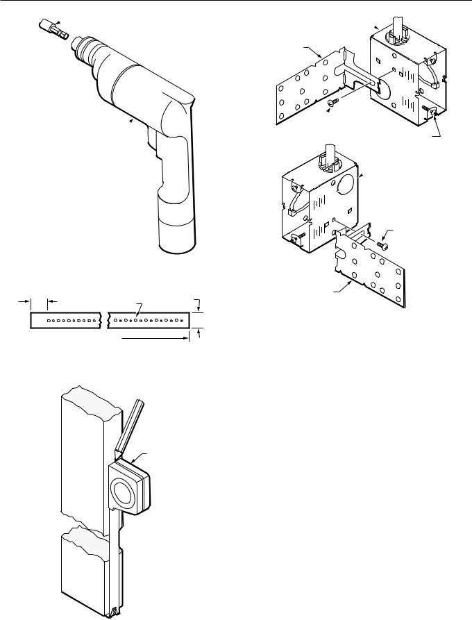
Mounting to Stud with Standard Electrical Box
Mounting to a stud using a standard electrical box requires the following equipment:
—Standard Utility Conduit Box CCT2967 (MVE2967) or Standard 4 x 4 in. Electrical Box CCT2960 (Fig. 27)
—One of the following (Fig. 28):
•Plastic Cable Assembly 14001491-001 (one pipe), -002 (two pipe), or -003 (three pipe) and Barb Couplings CCT1606B (MJP1606B) (5/32 x 1/4 in.) or CCT1628B (MJP1628B) (5/32 x 5/32 in.)
•Copper Cable Assembly 14001494-001 (one pipe), -002 (two pipe), or -003 (three pipe)
•1/2 in. emt conduit and 1/2 in. TW Setscrew Connector CCT2900 (MVE2900)
—Tape Measure CCT422
—No. 10 x 3 Pan Head Sheet Metal Screws CCT2317 (MVH2317) or 2-1/2 in. (64 mm) nails (two per stat)
—Stud Mount Box Clip CCT2642 for Standard Utility Conduit Box (Fig. 29)
—MFS Clip CCT2649E for Standard 4 x 4 in. Electrical Box (Fig. 29)
—If wall is to be plastered:
•Standoff Ring 14000885-001
•Fitting Finder 14000706-001
—Thermostat Tool CCT735A (MQT735A)
15 |
95-5597—1 |
 Loading...