


VisionPRO® IAQ
Total Home Comfort System
PRODUCT DATA
APPLICATION
The VisionPRO® IAQ Total Home Comfort System features an effortless, 7-Day programmable touchscreen thermostat that provides control of temperature, humidification, dehumidification, and ventilation.
FEATURES
•Large, clear display with backlight shows the current and set temperature and time—even in the dark.
•Touchscreen interaction
•Real-time clock keeps time during power failures and automatically updates to daylight savings.
•Change/check reminders let you know when to service or replace filters.
•Various Hold options allow you to override the program schedule, as desired.
•Controls humidification to increase homeowner comfort while protecting woodwork and furnishings.
•Controls dehumidification using air conditioner with high or low speed fan or a whole house dehumidifier.
•Controls ventilation with other HRV, ERV, or Freshair damper. Vent on demand and automatically using patented advanced ventilation control.
•Advanced heat pump control featuring balance point plus 2°F droop to increase homeowner comfort.
|
Contents |
Application/Features.......................................................... |
1 |
Specifications/Ordering Information .................................. |
2 |
Installation ........................................................................ |
4 |
Wiring ............................................................................... |
5 |
Power the Thermostat ...................................................... |
8 |
Installer Setup .................................................................. |
12 |
Operation .......................................................................... |
19 |
Programming .................................................................... |
25 |
Troubleshooting ................................................................ |
35 |
68-0287-1
VISIONPRO® IAQ TOTAL HOME COMFORT SYSTEM
SPECIFICATIONS
Thermostat Description:
Feature |
|
|
Description |
||
Powering method |
|
• |
Common wire only |
||
System types (up to |
• |
Gas, oil or electric heat with air |
|||
4 heat/2 cool) |
|
|
conditioning |
|
|
|
|
• Warm air, hot water, high-efficiency |
|||
|
|
|
furnaces, heat pumps, steam and |
||
|
|
|
gravity |
|
|
|
|
• Heat only with fan |
|
||
|
|
• |
Cool only |
|
|
Changeover |
|
Manual or Auto changeover selectable |
|||
|
|
|
|
|
|
System setting |
|
Heat-Off-Cool-Auto |
|
||
|
|
|
|
|
|
Fan setting |
|
Auto-On-Circ |
|
||
|
|
|
|
|
|
Electrical Ratings: |
|
|
|
||
|
|
|
|
||
Terminal |
Voltage (50/60 Hz) |
|
Running Current |
||
W1 Heating |
20 - 30 Vac |
|
.02 - 1.0A |
||
|
|
|
|
||
W2/Aux Heating |
20 - 30 Vac |
|
.02 - 1.0A |
||
|
|
|
|
||
W3/Aux2 Heating |
20 - 30 Vac |
|
.02 - 1.0A |
||
|
|
|
|
||
Y Cooling |
20 - 30 Vac |
|
.02 - 1.0A |
||
|
|
|
|
||
Y2 Cooling |
20 - 30 Vac |
|
.02 - 1.0A |
||
|
|
|
|
||
G Fan |
20 - 30 Vac |
|
.02 - 1.0A |
||
|
|
|
|
|
|
Temperature Setting Range:
Heating: 40°F to 90°F(4.5°C to 32°C).
Cooling: 50°F to 99°F (10°C to 37°C).
Operating Ambient Temperature:
VisionPRO® IAQ Thermostats: 0°F to 120°F (-18°C to 49°C).
THM5421C1008: -30°F to 150°F (-34°C to 66°C). C7089U1006: -40°F to 120°F (-40°C to 49°C). C7189U1005: 45°F to 88°F (7°C to 32°C).
Shipping Temperature:
VisionPRO® IAQ Thermostats: -30°F to 150°F (-34°C to 66°C).
THM5421C1008: -30°F to 150°F (-34°C to 66°C).
Operating Relative Humidity (Non-condensing):
VisionPRO® IAQ Thermostats: 5% to 90%. THM5421C1008: 5% to 90%. C7089U1006: 5% to 95%.
C7189U1005: 5% to 95%.
Humidification Setting Range:
Heating: 10% to 60% RH.
Dehumidification Setting Range:
Heating: 40% to 80% RH.
Humidity Display Range:
0% to 99%.
Cycle Rates (at 50% Load):
Heating: Selectable 1 - 12 cycles per hour.
Cooling: Selectable 1 - 6 cycles per hour.
Finish:
VisionPRO® IAQ Thermostats: Premier White® color. THM5421C1008: Premier White® color.
C7189U1005 Wall Mount Remote Indoor Sensor: Premier White® color.
Clock Accuracy: +/- 1 minute per year.
Resistance Characteristics of Remote Sensors:
C7089U1006 Outdoor Sensor: Negative temperature coefficient (NTC) means that resistance decreases as the temperature increases. See Table 12 in the Operation section for sensor resistance characteristics.
C7189U1005 Remote Indoor Sensor: Negative temperature coefficient (NTC), means that resistance decreases as the temperature increases. See Table 13 in the Operation section for sensor resistance characteristics.
Cool Indication:
VisionPRO® IAQ Comfort Systems show “Cool On” on the thermostat screen when Cool is activated.
Heat Indication:
VisionPRO® IAQ Comfort Systems show “Heat On” on the thermostat screen when Heat is activated.
Auxiliary Heat Indication:
VisionPRO® IAQ Comfort Systems show “Aux. Heat On” on the thermostat screen when Auxiliary Heat is activated.
Calibration:
C7089U1006, C7189U1005 and VisionPRO® IAQ Comfort Sys-
tems are factory-calibrated and require no field calibration.
Interstage Differential:
VisionPRO® IAQ Comfort Systems operate with droopless control. Once the thermostat senses that 1st stage is running at 90% capacity, the thermostat energizes 2nd stage.
Mounting Means:
VisionPRO® IAQ Comfort System: Thermostat mounts directly on the wall in the living space using mounting screws and anchors provided. Fits a vertical or horizontal 2 x 4 in. junction box.
THM5421C1008 Equipment Interface Module (EIM) mounts on HVAC equipment or on a wall in the equipment room.
C7089U1006 Outdoor Sensor: Mounts outside of living space with mounting clip and screws provided.
C7189U1005 Remote Indoor Sensor: Mounts directly on the wall using mounting screws and anchors provided.
Cover Plate:
32003796-001 Cover Plate is used to cover marks left on the wall by the old thermostat.
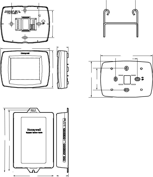
Dimensions:
VisionPRO® IAQ Comfort System: see Fig. 1. THM5421C1008: see Fig. 2
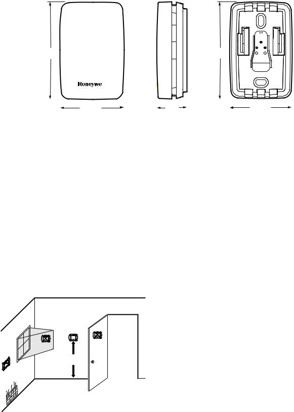
C7089U1006 Outdoor Sensor Mounting Clip: see Fig. 3. 32003796-001 Cover Plate: see Fig. 4.
C7189U1005 Remote Indoor Sensor: see Fig. 5.
68-0287—1 |
2 |
WALLPLATE  3-3/8 (86)
3-3/8 (86)
THERMOSTAT
AND WALLPLATE
THERMOSTAT
1-3/8 (35)
6 (152)
4-9/16
(116)
M23539
Fig. 1. VisionPRO® IAQ Comfort System
dimensions in in. (mm).
7-9/32
(185)
6-57/64
(175)
|
|
|
|
|
|
|
|
|
|
|
|
|
|
|
|
|
|
|
|
|
|
|
|
|
|
|
|
|
|
|
|
|
|
4-35/64 |
|
1-21/64 |
|||
|
|
|
|||||
|
|
(116) |
|
(34) |
|
||
FRONT VIEW |
SIDE VIEW |
|
M23544 |
Fig. 2. THM5421C1008 Equipment Interface Module
dimensions in in. (mm).
VISIONPRO® IAQ TOTAL HOME COMFORT SYSTEM
 1-1/2 (38)
M4488
Fig. 3. C7089U1006 Outdoor Sensor Mounting Clip dimensions in in. (mm).
7-7/8 (200)
 3-5/16 (84)
5-1/2
(140)
3-5/16
(84)
M22139
Fig. 4. 32003796-001 Cover Plate dimensions in in. (mm).
3 |
68-0287—1 |
VISIONPRO® IAQ TOTAL HOME COMFORT SYSTEM
2-9/32 |
2-9/32 |
(58) |
(58) |
|
|
|
|
|
|
45/64 |
|
|
|
|
|
|
|
|
|
|
|
|
|
|
|
|
|
|
|
|
|
|
|
|
|
|
|
|
|
|
|
|
|
|
|
|
|
|
|
|
|
|
|
|
|
|
|
|
|
|
|
|
|
|
|
1-1/2 (38) |
|
|
|
|
|
1-1/2 (38) |
|
||
|
|
|
|
|
|
|
|
||||
|
|
|
|
|
(18) |
|
|
|
|
|
|
M23522 |
FRONT VIEW |
|
SIDE VIEW |
FRONT VIEW (COVER OFF) |
|||||||
Fig. 5. C7189U1005 Remote Indoor Sensor dimensions in in. (mm).
INSTALLATION
When Installing this Product...
1.Read these instructions carefully. Failure to follow the instructions can damage the product or cause a hazardous condition.
2.Check the ratings given in the instructions to make sure the product is suitable for your application.
3.Installer must be a trained, experienced service technician.
4.After completing installation, use these instructions to verify the product operation.
Selecting Location
Install the thermostat about 5 ft. (1.5m) above the floor in an area with good air circulation at average temperature. See Fig. 6.
NO
|
YES |
|
NO |
NO |
5 FEET |
[1.5 METERS]
Do not install the thermostat where it can be affected by:
—Drafts or dead spots behind doors and in corners.
—Hot or cold air from ducts.
—Radiant heat from sun or appliances.
—Concealed pipes and chimneys.
—Unheated (uncooled) areas such as an outside wall behind the thermostat.
Installing Wallplate
 CAUTION
Electrical Hazard.
Can cause electrical shock or equipment damage.
Disconnect power before wiring.
The thermostat can be mounted horizontally on the wall or on a 4 in. x 2 in. (101.6 mm x 50.8 mm) wiring box.
1.Position and level the wallplate (for appearance only).
2.Use a pencil to mark the mounting holes.
3.Remove the wallplate from the wall and, if drywall, drill two 3/16-in. holes in the wall, as marked. For firmer material such as plaster, drill two 7/32-in. holes. Gently tap anchors (provided) into the drilled holes until flush with the wall.
M19925
Fig. 6. Selecting thermostat location.
68-0287—1 |
4 |
4.Position the wallplate over the holes, pulling wires through the wiring opening. See Fig. 7.
5.Insert the mounting screws into the holes and tighten.
WALL
WIRES THROUGH WALL
AND WIRE SLOT
 WALL ANCHORS (2)
MOUNTING
HOLES
M23541
MOUNTING
SCREWS (2)
M23543
Fig. 7. Mounting wallplate.
Installing Equipment Interface Module (EIM)
 CAUTION
Electrical Hazard.
Can cause electrical shock or equipment damage.
Disconnect power before wiring.
The EIM can be mounted vertically on the HVAC equipment or on a wall in the equipment room.
1.Position the EIM.
2.Use a pencil to mark the mounting holes.
3.Remove the wallplate from the wall and, if drywall, drill two 3/16-in. holes in the wall, as marked. For firmer material such as plaster, drill two 7/32-in. holes. Gently tap anchors (provided) into the drilled holes until flush with the wall.
4.Position the wallplate over the holes, pulling wires through the wiring opening.
5.Insert the mounting screws into the holes and tighten. See Fig. 8.
Communication LED
The EIM has an LED (see Fig. 8) that communicates the EIM status as follows.
•LED blinks rapidly: Normal information transfer.
•LED blinks once: Incoming message to EIM.
•LED blinks continuously: Wiring problem. Check wiring to terminals 1, 2, 3.
•LED always off: Wiring problem. Check wiring to terminals 1, 2, 3.
•LED always on: EIM may need replacement.
VISIONPRO® IAQ TOTAL HOME COMFORT SYSTEM
NOTE: It is normal for the LED to blink continuously during startup, and while checking equipment status (Auto Discover mode).
WALL ANCHOR
COMMUNICATION LED
DRILL 3/16 IN. HOLES FOR DRYWALL. DRILL 7/32 IN. HOLES FOR PLASTER
MOUNTING SCREW |
M23484 |
Fig. 8. Mounting EIM.
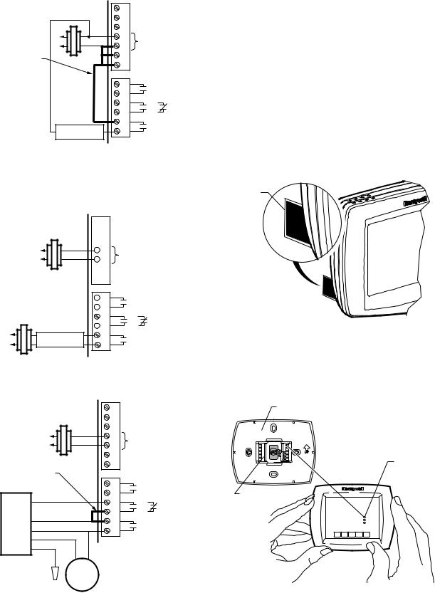
WIRING
All wiring must comply with local electrical codes and ordinances. See Fig. 10–20.
1.Select set of terminal identifications (Table 1) that corresponds with system type.
2.Loosen the screws for the appropriate system type selected; see Table 1. See Table 2 for terminal designation descriptions. Insert wires in the terminal block under the loosened screw. See Fig. 9.
3.Securely tighten each screw.
4.Push excess wire back into the hole.
5.Plug the hole with nonflammable insulation to prevent drafts from affecting the thermostat.
6.See Fig. 10–20 for typical wiring hookups.
Table 1. Selecting Terminal Identifications for System Type.
|
Wallplate Terminal |
Wiring Diagram |
System Type |
Identifications |
Reference |
|
|
|
Standard Heat/Cool |
Conventional |
10, 11 |
Standard Multistage |
Conventional |
12 |
up to 3 Heat/2 Cool |
|
|
Heat Pump with |
Heat Pump |
13 |
Auxiliary Heat |
|
|
5 |
68-0287—1 |
VISIONPRO® IAQ TOTAL HOME COMFORT SYSTEM
M23541
Fig. 9. Inserting wires in terminal block.
IMPORTANT
Use 18-gauge thermostat wire.
Table 2. Terminal Designation Descriptions.
THM5421C1008 |
|
Terminal |
|
Designations |
Function |
|
|
1 |
Terminal 1—data to/from thermostat |
2 |
Terminal 2—power from thermostat (24Vac) |
|
|
3 |
Terminal 3—common from thermostat |
|
(24Vac) |
C |
24 Vac Transformer Common |
|
|
R |
24 Vac Transformer |
|
|
RC |
24 Vac Cooling Transformer |
|
|
RH |
24 Vac Heating Transformer |
|
|
HUM1/HUM2 |
Humidification Connection (normally open) |
|
|
DHM1/DHM2 |
Dehumidification Connection (normally |
|
open or closed based on installer setup) |
VNT1/VNT2 |
Ventilation connection (normally open) |
|
|
W1/O/B |
Stage 1 Heating Relay (Conventional) |
|
Change-over Relay (Heat Pump) |
W2/AUX |
Stage 2 Heating Relay (Conventional) |
|
Auxiliary Heat (fossil fuel or electric) (Heat |
|
Pump) |
W3/AUX2 |
Stage 3 Heating Relay (Conventional) |
|
Auxiliary Heat (fossil fuel or electric) (Heat |
|
Pump) |
Y |
Stage 1 Compressor Relay |
|
|
Y2 |
Stage 2 Compressor Relay |
|
|
G |
Fan Relay |
|
|
L |
Heat Pump Equipment Monitor |
|
|
OUT1/OUT2 |
Outdoor Temperature Sensor |
|
|
IN1/IN2 |
Remote Indoor Temperature Sensor |
|
|
DATS1/DATS2 |
Discharge Air Temperature Sensor |
|
|
NOTES:
1.When used in a single-transformer system, leave the metal jumper wires in place between R and Rc, and Rc and Rh. If used on a two-transformer system, remove metal jumper wire between Rc and Rh.
2.If thermostat is configured for a heat pump system in the Installer Setup, configure changeover valve for cool (O-factory setting) or heat (B).
For wiring to a W8835 Zone panel please refer to the product data sheet included with the panel.
1 |
|
1 |
1 |
2 |
2 |
3 |
3 |
|
C |
|
R |
|
RC |
|
RH |
COMMUNICATION LED |
|
|
COMMUNICATION |
CONV. HP |
|
TERMINALS |
W1 |
O/B |
|
||
|
W2 |
AUX |
24 VAC |
W3 |
AUX2 |
|
Y |
Y |
|
Y2 |
Y2 |
|
G |
G |
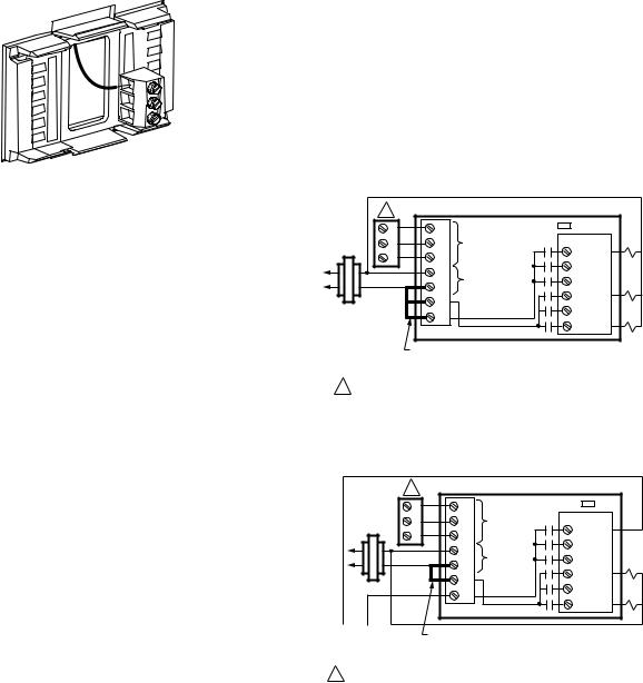
FACTORY INSTALLED
JUMPER BETWEEN R,
RC AND RH
1 WIRE TO TERMINALS ON THERMOSTAT. |
M23485 |
Fig. 10. Typical hookup of conventional single-stage heat and cool system with single transformer
(1H/1C conventional).
1 |
|
|
|
|
1 |
1 |
COMMUNICATION LED |
|
|
2 |
2 |
COMMUNICATION |
CONV. HP |
|
3 |
3 |
TERMINALS |
W1 |
O/B |
|
||||
|
W2 |
AUX |
||
|
C |
|
||
|
24 VAC |
W3 |
AUX2 |
|
|
R |
|||
|
|
Y |
Y |
|
|
RC |
|
||
|
|
Y2 |
Y2 |
|
|
RH |
|
||
|
|
G |
G |
|
|
|
|
||
OIL PRIMARY/ |
FACTORY INSTALLED JUMPER BETWEEN R, |
|
AQUASTAT |
AND RC (REMOVE FACTORY INSTALLED |
|
|
JUMPER BETWEEN RC AND RH |
|
|
|
|
1 WIRE TO TERMINALS ON THERMOSTAT. |
M23486 |
|
Fig. 11. Typical hookup of conventional single-stage heat and cool system with oil primary (1H/1C conventional).
68-0287—1 |
6 |

KEY
=NORMALLY OPEN, DRY CONTACTS
=NORMALLY CLOSED, DRY CONTACTS
M23685
1 |
|
|
|
|
HEAT 1 RELAY |
|
1 |
1 |
COMMUNICATION LED |
|
|||
|
|
|||||
2 |
2 |
COMMUNICATION |
CONV. HP |
HEAT 2 RELAY |
||
TERMINALS |
W1 |
O/B |
||||
3 |
3 |
|||||
|
|
|||||
|
W2 |
AUX |
|
|||
|
C |
|
HEAT 3 RELAY |
|||
|
24 VAC |
W3 AUX2 |
||||
|
R |
|
||||
|
|
Y |
Y |
COOL 1 RELAY |
||
|
RC |
|
||||
|
|
Y2 |
Y2 |
|
||
|
RH |
|
COOL 2 RELAY |
|||
|
|
G |
G |
|||
|
|
|
||||
|
|
|
|
|||
FACTORY INSTALLED |
|
FAN RELAY |
|
|
|
||
JUMPER BETWEEN R, |
|
|
|
RC AND RH |
|
|
|
1 WIRE TO TERMINALS ON THERMOSTAT. |
|
M23487 |
|
Fig. 12. Typical hookup of conventional system with up to three-stage heat and two-stage cool with one transformer (3H/2C, 2H/2C, 2H/1C, 1H/2C, 1H/1C conventional).
1 |
|
|
|
|
CHANGEOVER |
|
1 |
1 |
COMMUNICATION LED |
|
|||
|
|
|||||
2 |
2 |
COMMUNICATION |
CONV. HP |
AUX 1 (HEAT 3) |
||
TERMINALS |
W1 |
O/B |
||||
3 |
3 |
|||||
|
|
|||||
|
W2 |
AUX |
|
|||
|
C |
|
AUX 2 (HEAT 4) |
|||
|
24 VAC |
W3 AUX2 |
||||
|
R |
|
||||
|
|
Y |
Y |
COMP 1 |
||
|
RC |
|
||||
|
|
Y2 |
Y2 |
|
||
|
RH |
|
COMP 2 |
|||
|
|
G |
G |
|||
|
|
|
||||
|
|
|
|
|||
FACTORY INSTALLED |
|
FAN RELAY |
|
|
|
||
JUMPER BETWEEN R, |
|
|
|
RC AND RH |
|
|
|
1 WIRE TO TERMINALS ON THERMOSTAT. |
|
M23488 |
|
Fig. 13. Typical hookup of heat pump system (up to 4H/2C heat pump).
FIELD INSTALLED JUMPER BETWEEN R AND HUM 1
|
1 |
|
|
2 |
|
|
3 |
|
|
C |
24 VAC |
|
R |
|
|
|
|
|
RC |
|
|
RH |
|
|
H1 |
|
NON-POWERED |
U |
|
M2 |
|
|
HUMIDIFIER |
|
|
D1 |
|
|
|
OR |
|
|
H |
|
|
M2 |
|
|
V1 |
|
|
N |
|
|
T2 |
|
|
|
M23489 |
Fig. 14. Typical hookup of non-powered humidifier.
VISIONPRO® IAQ TOTAL HOME COMFORT SYSTEM
 1
1
 2
2
 3
3
 C
C
24 VAC
 R
R
|
RC |
|
|
RH |
|
POWERED |
H1 |
|
U |
||
HUMIDIFIER |
||
M2 |
||
|
D1
H OR
 M2
M2
 V1
V1
N
 T2
T2
M23490
Fig. 15. Typical hookup of powered humidifier.
|
1 |
|
|
2 |
|
|
3 |
|
|
C |
24 VAC |
|
R |
|
|
|
|
|
RC |
|
FIELD INSTALLED |
RH |
|
|
|
|
JUMPER BETWEEN |
|
|
R AND DHM 1 |
H1 |
|
|
U |
|
|
M2 |
|
|
D1 |
OR |
LOW SPEED |
H |
|
M2 |
|
|
FAN |
|
|
V1 |
|
|
|
|
|
|
N |
|
|
T2 |
|
|
|
M23491 |
Fig. 16. Typical hookup of variable speed blower for dehumidification in low speed (contacts normally closed).
NOTE: Connect DHM2 to low-speed fan terminal on air handler for dehumidification with air conditioner and a low-speed fan.
 1
1
 2
2
 3
3
 C
C
24 VAC
 R
R
 RC
RC  RH
RH
 H1
H1
U
 M2
M2
POWERED |
D1 |
|
|
H |
OR |
||
DEHUMIDIFIER |
|||
M2 |
|
||
|
|
 V1
V1
N
 T2
T2
M23492
Fig. 17. Typical hookup of powered whole house dehumidifier (contacts normally open).
7 |
68-0287—1 |
VISIONPRO® IAQ TOTAL HOME COMFORT SYSTEM
FIELD INSTALLED JUMPER BETWEEN R AND VNT 1
|
1 |
|
|
2 |
|
|
3 |
|
|
C |
24 VAC |
|
R |
|
|
|
|
|
RC |
|
|
RH |
|
|
H1 |
|
|
U |
|
|
M2 |
|
|
D1 |
OR |
|
H |
|
|
M2 |
|
|
V1 |
|
NON-POWERED |
N |
|
T2 |
|
|
VENTILATOR |
|
|
|
M23493 |
|
|
|
Fig. 18. Typical hookup of fresh air damper.
NOTE: Use this hookup for ventilation using a fresh air damper.
 1
1
 2
2
 3
3
 C
C
24 VAC
 R
R
 RC
RC  RH
RH
 H1
H1
U
 M2
M2
D1
H OR
 M2
M2
POWERED |
V1 |
|
N |
||
VENTILATOR |
||
T2 |
||
|
M23494
Fig. 19. Typical hookup of powered ventilation.
|
1 |
|
|
2 |
|
|
3 |
|
|
C |
24 VAC |
|
R |
|
|
|
|
|
RC |
|
|
RH |
|
FIELD INSTALLED |
|
|
JUMPER BETWEEN |
H1 |
|
DHM 1 AND VNT 1 |
|
|
U |
|
|
BLUE |
M2 |
|
D1 |
OR |
|
|
H |
|
|
M2 |
|
YELLOW
V1
DH90 N
GREEN
T2
RED
WHITE
FRESH
AIR
DAMPER
M23495
Fig. 20. Hookup of Honeywell DH90 with fresh air intake for ventilation.
POWER THE THERMOSTAT
• 24 Vac common wire only to EIM or zone panel.
Wiring 24 Vac Common
•Single-Transformer System—Connect the common side of the transformer to the C screw terminal of the EIM. Leave the metal jumper wires in place between R, Rc, and RH.
•Two-Transformer System—Connect the common side of the cooling transformer to the C screw terminal of the EIM. Remove the metal jumper wire between Rc and Rh. Connect the hot side of heating transformer to Rh and leave the jumper wire between R and Rc and connect the hot side of cooling transformer to R or Rc.
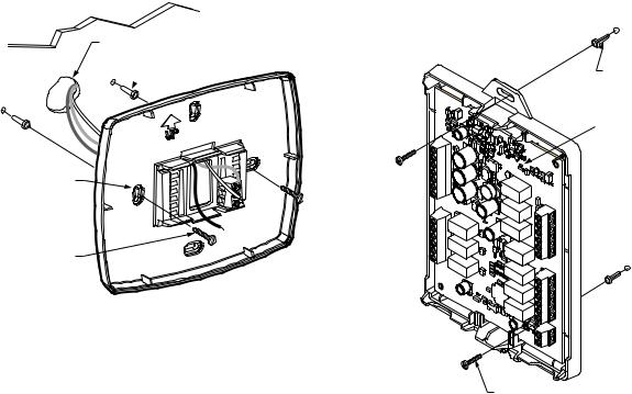
1.Locate and remove the tab labeled, Remove, in the lower left corner on the thermostat back. See Fig. 21.
REMOVE
TAB
DURINGINSTALLATION
REMOVE
DURINGINSTALLATION
REMOVE
M19920
Fig. 21. Remove tab labeled, Remove, on thermostat back
Mount Thermostat to Wallplate
1.Align the terminal screw blocks with the pins on the back of the thermostat. Push the thermostat straight onto the wallplate until it snaps into place. See Fig. 22.
WALLPLATE
PINS ON
BACK OF
THERMOSTAT
TERMINAL
SCREW
BLOCK
M23542
Fig. 22. Mount thermostat to wallplate.
68-0287—1 |
8 |
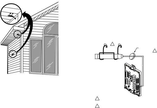
Locate and Mount C7089U1006 Outdoor Temperature Sensor (Optional)
Mount the sensor where (see Fig. 23):
•cannot tamper with settings.
•there is good air circulation.
•it can measure true outdoor ambient temperature.
•surface is flat.
•wire distance between C7089U1006 and EIM is less than 200 feet.
Do not mount the sensor:
•in direct sunlight.
•where hot or cold air blows on the sensor. Discharge line from an outdoor compressor unit, vent or fan causes inaccurate temperature readings.
•where snow, ice or debris can cover it.
Use the following steps to mount the sensor:
1.Remove the sensor from the mounting clip.
2.Mark the area on the location selected for mounting the sensor mounting clip.
3.Mount the clip.
VISIONPRO® IAQ TOTAL HOME COMFORT SYSTEM
IMPORTANT
Erratic temperature readings from a sensor can occur as a result of any of the wiring practices described below. Avoid these practices to assure correct operation. Use shielded cable to reduce interference if rerouting sensor wiring is not possible.
—Be sure wires have a cable separate from the thermostat cable.
—Do not route temperature sensor wiring with building power wiring, next to control contactors or near light dimming circuits, electric motors or welding equipment.
—Avoid poor wiring connections.
—Avoid intermittent or missing building earth ground.
 CAUTION
Electrical Shock Hazard.
Can cause electrical shock or equipment damage.
Disconnect power supply before connecting wiring.
Wiring must comply with applicable codes, ordinances and regulations:
1.Wire C7089U1006 Outdoor Sensor to OUT1and OUT2 terminals on the EIM. If leadwire provided is not long enough (60 in.), run a cable to a hole at C7089U1006 location.
a.Using color-coded, 18-gauge thermostat wire is recommended. For example of general wiring of C7089U1006, see Fig. 24.
b.Pigtail wiring can be used.
2.Mount C7089U1006 in its mounting clip.
3.Plug wiring hole using nonhardening caulk or putty.
1 |
|
|
|
WIRING HOLE |
|
C7089 |
THROUGH |
2 |
|
STRUCTURE |
|
M7514
Fig. 23. Typical locations for C7089U1006 Outdoor Sensor.
Wire C7089U1006 Outdoor Sensor
 CAUTION
Electrical Interference (Noise) Hazard. Can cause erratic system operation.
Keep wiring at least one foot away from large inductive loads such as motors, line starters, lighting ballasts and large power distribution panels.
Use shielded cable to reduce interference when rerouting is not possible.
1USE APPROPRIATE MOUNTING MEANS FOR THE TYPE OF STRUCTURE.
2PLUG WIRING HOLE WITH NON-HARDENING CAULK
OR PUTTY. |
M23525 |
Fig. 24. Wire C7089U1006 Outdoor Sensor to the EIM.
If an outdoor temperature sensor is installed, the thermostat displays the outside temperature in the lower right corner of the Home Screen.
9 |
68-0287—1 |

VISIONPRO® IAQ TOTAL HOME COMFORT SYSTEM
MON |
TUE |
WED |
THU |
FRI |
SAT |
SUN |
FAN |
|
|
|
|
|
|
|
Inside |
|
|
Set To |
|
|
AUTO |
|
|
|
|
|
|
SYSTEM |
|
|
|
Following |
|
|
|
|
|
Schedule |
|
||
|
|
|
|
|
||
HEAT |
|
|
|
Outside |
|
|
|
|
|
|
|
|
|
|
|
AM |
|
|
|
|
|
SCHED |
HOLD |
CLOCK |
SCREEN |
MORE |
|
M22453
If thermostat is set to Auto Changeover System mode, press the More key until the outside temperature is shown on the screen.
MON |
TUE |
WED |
THU |
FRI |
SAT |
SUN |
|
|
|
|
Outside |
|
|
|
SCHED |
HOLD |
CLOCK |
SCREEN |
|
|
DONE |
|
WAKE |
LEAVE |
RETURN |
SLEEP |
CANCEL |
|
|
|
|
|
|
M22448 |
Locate and Mount C7189U1005 Remote
Indoor Temperature Sensor (Optional)
1.Choose a location (see Fig. 25) for mounting the sensor on an inside wall about 5 ft (1.5m) above the floor.
2.Be sure wire distance between C7189U1005 and EIM is less than 200 feet.
3.Make sure there is good air circulation at average temperature at the chosen location. Avoid the following locations because they can introduce errors in sensor
measurements. See Fig. 25.
a.Hot areas caused by: (a)Concealed pipes or ducts.
(b)Drafts from fireplaces or other heat sources. (c)Convection or radiant heat from the sun or
electrical equipment.
b.Cold areas caused by:
(a)Concealed pipes or ducts. (b)Drafts from windows and doors.
(c)Unheated areas on the other side of the wall location.
c. Dead air areas:
(a)Behind doors, furniture and curtains. (b)In corners and alcoves.
4.Mark the area on the wall selected for mounting the C7189U1005 Sensor.
5.Run wire cable to a hole at the selected wall location. Pull approximately three inches of wire through the opening. Color-coded, 18-gauge thermostat wire is recommended.
YES
NO
NO
5 FEET
(1.5 METERS)
NO
M4476
Fig. 25. Typical location for C7189U1005 Indoor Sensor.
Wire C7189U1005 Indoor Sensor
 CAUTION
Electrical Interference (Noise) Hazard. Can cause erratic system operation.
Keep wiring at least one foot away from large inductive loads such as motors, line starters, lighting ballasts and large power distribution panels.
IMPORTANT
Erratic temperature readings from a sensor can occur as a result of any of the wiring practices described below. Avoid these practices to assure correct operation.
—Be sure wires have a cable separate from the thermostat cable.
—Do not route temperature sensor wiring with building power wiring, next to control contactors or near light dimming circuits, electric motors or welding equipment.
—Avoid poor wiring connections.
—Avoid intermittent or missing building earth ground.
 CAUTION
Electrical Shock Hazard.
Can cause electrical shock or equipment damage.
Disconnect power supply before connecting wiring.
Wiring must comply with applicable codes, ordinances and regulations.
1.Wire C7189U1005 Indoor Sensor to IN1and IN2 terminals on the EIM. For an example of general wiring of C7189U1005, see Fig. 26 to wire one sensor and Fig. 27 to wire multiple sensors.
2.Push excess wire back into the hole. Plug the hole using nonhardening caulk, putty or insulation to prevent drafts from affecting performance.
3.Remove C7189U1005 cover.
4.Mount C7189U1005 to the wall using the screws and anchors provided.
5.Level the C7189U1005 for appearance only. Device functions correctly even when not level.
6.Install C7189U1005 cover.
68-0287—1 |
10 |
L |
C7189 |
 1 OUT
1 OUT
 2 OUT
2 OUT
 1 IN
1 IN
 2 IN
2 IN
M23523
Fig. 26. Wiring a single C7189U1005 Indoor Sensor.
L |
|
|
|
|
1 OUT |
|
|
|
|
2 OUT |
|
|
|
|
1 IN |
C7189 |
C7189 |
|
|
2 IN |
|
|||
|
|
|
||
|
C7189 |
C7189 |
|
|
L |
|
|
|
|
1 OUT |
|
|
|
|
2 OUT |
|
|
|
|
1 IN |
C7189 |
C7189 |
C7189 |
|
2 IN |
||||
|
|
|
||
|
C7189 |
C7189 |
C7189 |
|
|
C7189 |
C7189 |
C7189 |
|
|
|
|
M23524 |
Fig. 27. Wiring Multiple C7189U1005 Sensors.
If a remote indoor temperature sensor is installed, the thermostat has several options for displaying the current indoor temperature. This is configured in ISU 340. The thermostat can display either the temperature measured at the thermostat location, the sensor location, or a 50-50 average of both.
ONE REMOTE INDOOR SENSOR INSTALLED (OPTIONAL)
If one remote indoor temperature sensor is used, based on configuration during installer setup, either of the following options are available:
•The thermostat will display the temperature measured at the sensor location (internal thermostat sensor is disabled).
•The thermostat will display a 50-50 average of the temperature measured at the thermostat location and the remote indoor sensor location.
MULTIPLE REMOTE INDOOR SENSORS INSTALLED (OPTIONAL)
If more than one remote indoor sensor is used, based on configuration during installer setup, either of the following options are available:
VISIONPRO® IAQ TOTAL HOME COMFORT SYSTEM
•The thermostat will display the temperature measured at the sensor locations (internal thermostat sensor is disabled). Sensors must be in square numbers (e.g., 4, 9, 16, and so on) and the displayed temperature will be an average of the temperatures measured at each location.
•The thermostat will display a 50-50 average of the temperature measured at the thermostat location and the average of the temperatures measured at the remote indoor sensor locations. In this case, the thermostat sensor still carries a 50% weighting of the displayed temperature.
Install Discharge Air Temperature Sensor (Optional):
Prior to installing Discharge Air Temperature Sensor (DATS) refer to the installation instructions included with the product for more information on placement and wiring.
When using a DATS with network zoning the DATS will monitor the duct air temperature and communicate with the thermostat and will disable the heating and/or cooling if installer set high or low temperature limits are reached.
When using a DATS with an Equipment Interface Module the DATS is for testing only. When the installer is in any of the Installer Tests pressing the “More” button will display the temperature measured at the DATS. This allows the installer to view the temperature of each stage of heating and or cooling. The DATS will not be used for control and will not disable heating or cooling based on duct air temperature.
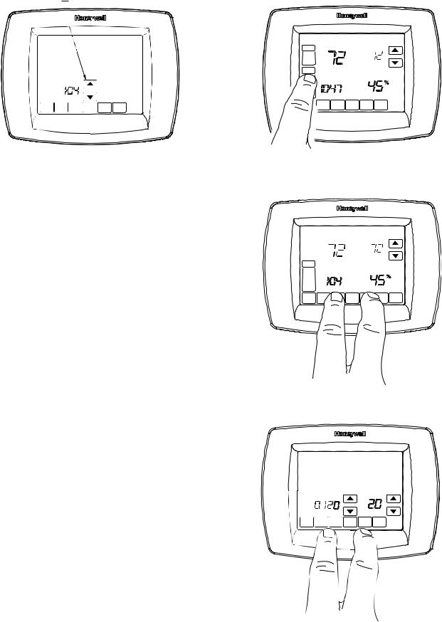
Set Calendar and Time
Thermostat keeps current time and day for up to ten years under normal use after the calendar is set.
When the thermostat is first powered, the display is ready to set the calendar and time.
NOTE: Calendar can also be set in the Installer Setup.
1.Press the arrow keys to set the year, month and day.
2.Press the Done key.
SET CURRENT DAY
SET MONTH
MO |
WE |
TH |
FR |
SA |
SU |
OK TO PICK MULTIPLE DAYS |
SCREEN LOCKED |
|
|||
|
CHANGE FILTER UV LAMP |
|
|
||
DONE
USE ARROWS TO SET YEAR AND TIME
M22424
3.Press the arrow keys to set the current time.
4.Press the Done Key.
11 |
68-0287—1 |
VISIONPRO® IAQ TOTAL HOME COMFORT SYSTEM
1. Press and release the System Key.
USE ARROWS TO SET YEAR AND TIME
MO |
WE |
TH |
FR |
SA |
SU |
THU |
|
||||||
|
|
|
|
|
FAN |
|
|
|
|
|
|
ON Inside |
|
|
|
|
|
|
AUTO |
|
|
|
|
|
|
SYSTEM |
Following |
|
|
|
|
|
EM HEAT |
Schedule |
|
|
|
|
|
OFF |
A |
|
|
|
|
|
COOL |
|
|
|
|
|
|
M |
|
|
|
|
|
|
|
Humidity |
|
|
|
|
|
SCHED |
HOLD CLOCK SCREEN |
DONE
M22425
INSTALLER SETUP
Auto Discover is available when the TH9421C thermostat is connected to an EIM. The EIM communicates information to the thermostat. Thermostat settings can be specified using the up and down arrow keys on the screen or set to Auto Discover.
Using Auto Discover
Some Installer setups are defaulted to Auto Discover. If not defaulted, the installer can change the option to Auto Discover, however, it is always important that the installer verify that the auto discovered values are correct for the system that is present.
When using the thermostat with an equipment interface module, Auto Discover will discover factory default settings and will not receive communications as to proper system settings. The equipment interface module is preprogrammed at the factory as a one heat one cool product and the thermostat will “auto discover” those settings. The equipment interface module will be reprogrammed when the installer manually changes the configuration in the installer set up. It is not recommended to use Auto Discover with an equipment interface module.
When using the VisionPRO® IAQ thermostat with a W8835 zone panel, configure the zone panel, using the DIP switches on the panel, for the proper system settings. Enter the installer setup on each thermostat and assign zone numbers, and change the system settings (ISU 172–180) to Auto Discover
(E) then press the discover button on the zone panel. The zone panel will then communicate those settings back to the thermostats and the thermostats will automatically configure the ISU settings in Auto Discover, again it is important to verify that the auto discovered values are correct.
NOTE: When a VisionPRO® IAQ thermostat is being added to an existing zoning system with T8635 Thermostats the new VisionPRO® IAQ must be set up as the Zone One Thermostat (master zone controller), and can only be used with a W8835 zone panel.
Follow these steps to enter the Installer Setup:
M23498
2.Press and hold the two blank keys on either side of the center blank key for approximately five seconds until screen changes.
MO |
TU |
WE |
TH |
FR |
SA |
SU |
OK TO PICK MULTIPLE DAYS |
SCREEN LOCKED |
|||||
|
CHANGE FILTER UV LAMP |
|
|
|||
|
Inside |
|
|
Set |
|
|
SYSTE |
|
|
|
Following |
|
|
M |
|
|
|
Schedule |
|
|
|
|
|
|
|
|
|
EM |
|
|
|
|
|
|
HEAT |
|
|
|
|
|
|
OFF |
|
|
|
Humidity |
|
|
DONE |
|
|
|
|
|
CANCEL |
M23499
3.Release the two blank keys when the screen on the thermostat matches the screen below.
DONE
M22442
68-0287—1 |
12 |
 Loading...