


Honeywell UDC 2300, UDC 3000, UDC 3300, UDC 5000, UDC 6000 User Manual
...UDC 2300
UDC 3000
UDC 3300
UDC 5000
UDC 6000
UDC 6300 Universal Digital Controllers
RS422/485 ASCII Communications
Option
Product Manual
51-51-25-35G 5/99

Copyright, Notices, and Trademarks
Printed in U.S.A. – © Copyright 1999 by Honeywell Inc.
Rev G, 5/99
While this information is presented in good faith and believed to be accurate, Honeywell disclaims the implied warranties of merchantability and fitness for a particular purpose and makes no express warranties except as may be stated in its written agreement with and for its customer.
In no event is Honeywell liable to anyone for any indirect, special, or consequential damages. The information and specifications in this document are subject to change without notice.
This document was prepared using Information Mapping® methodologies and formatting principles.
UDC 2300, UDC 3000, UDC 3300, UDC 5000, UDC 6000, and UDC 6300 are U.S. trademarks of Honeywell Inc.
Information Mapping® is a registered trademark of Information Mapping, Inc.
Honeywell
Industrial Automation and Control
Automation College
100 Virginia Drive
Fort Washington, PA 19034
ii |
RS422/485 ASCII Communications Option Product Manual |
5/99 |

About This Publication
The UDC manual for RS422/485 ASCII communications option contains the following sections:
Section 1 |
– |
Overview |
Section 2 |
– |
Installation |
Section 3 |
– |
Establishing Communications |
Section 4 |
– Read and Write Operations |
|
Section 5 |
– Reading, Writing, and Overriding Parameters on UDC 3000 |
|
|
|
Versa-Pro Controllers |
Section 6 |
– Reading, Writing and Overriding Parameters on UDC 5000 |
|
|
|
Ultra-Pro Controllers |
Section 7 |
– Reading, Writing, and Overriding Parameters on UDC 6000 |
|
|
|
Process Controllers |
Section 8 |
– Reading, Writing, and Overriding Parameters on UDC 6300 |
|
|
|
Process Controllers |
Section 9 |
– Reading, Writing, and Overriding Parameters on UDC 3300 |
|
|
|
Process Controllers |
Section 10 |
– Reading, Writing, and Overriding Parameters on UDC 2300 |
|
|
|
Process Controllers |
Section 11 |
– Operating the Controller with Communications Option |
|
Section 12 |
– |
ASCII Conversion Table |
Section 13 |
– |
Cable Specifications |
Communication between your computer and the UDC Controller is accomplished for one piece of information (parameter) at a time. Each parameter has an associated identifying code.
The Identifying Code and Format Code will be listed along with information pertaining to that parameter.
The identifying codes are grouped in the same order as they appear in the controller configuration prompts.
5/99 |
RS422/485 ASCII Communications Option Product Manual |
iii |

|
Contents |
|
SECTION 1 – OVERVIEW .................................................................................................. |
1 |
|
1.1 |
Introduction ................................................................................................... |
1 |
1.2 |
Message Exchange Protocols ...................................................................... |
2 |
1.3 |
Field Upgrade ............................................................................................... |
3 |
SECTION 2 – INSTALLATION ........................................................................................... |
5 |
|
2.1 |
Introduction ................................................................................................... |
5 |
2.2 |
RS232 to RS485 Converters ........................................................................ |
6 |
2.3 |
Using a Black Box Converter........................................................................ |
7 |
2.4 |
Using a Westermo Converter ....................................................................... |
9 |
2.5 |
Wiring Diagrams ......................................................................................... |
11 |
SECTION 3 – ESTABLISHING COMMUNICATIONS AND TESTING ............................ |
15 |
|
3.1 |
Preparing the Controller for Communications............................................. |
15 |
3.2 |
Programming .............................................................................................. |
19 |
3.3 |
Message Exchange .................................................................................... |
20 |
3.4 |
Request Messages ..................................................................................... |
21 |
3.5 |
Response Messages .................................................................................. |
24 |
3.6 |
Status Codes .............................................................................................. |
26 |
3.7 |
Checksum Protocol (for Data Security) ...................................................... |
28 |
3.8 |
Shed ........................................................................................................... |
34 |
3.9 |
Loopback (UDC 2300, UDC 3000, UDC 3300 Only) .................................. |
35 |
3.10 |
Recovering from Communications Failures................................................ |
37 |
SECTION 4 – READ AND WRITE OPERATIONS ........................................................... |
41 |
|
4.1 |
Read Operations......................................................................................... |
41 |
4.2 |
Read Analog Parameters ........................................................................... |
42 |
4.3 |
Read Digital Parameters............................................................................. |
45 |
4.4 |
Write Operations......................................................................................... |
47 |
4.5 |
Write Analog Parameters............................................................................ |
48 |
4.6 |
Write Digital Parameters............................................................................. |
52 |
SECTION 5 – READ, WRITE AND OVERRIDE PARAMETERS – UDC3000 ................. |
55 |
|
5.1 |
UDC 3000 Overview ................................................................................... |
55 |
5.2 |
UDC 3000 Reading Control Data ............................................................... |
57 |
5.3 |
UDC 3000 Read Option Status................................................................... |
58 |
5.4 |
UDC 3000 Miscellaneous Read Only’s....................................................... |
59 |
5.5 |
UDC 3000 Setpoints ................................................................................... |
61 |
5.6 |
UDC 3000 Using a Computer Setpoint....................................................... |
62 |
5.7 |
UDC 3000 Overriding Input 1 ..................................................................... |
63 |
5.8 |
UDC 3000 Canceling the Override ............................................................. |
64 |
5.9 |
UDC 3000 Reading or Changing the Output .............................................. |
65 |
5.10 |
UDC 3000 Local Setpoint/PID Set Selection /Setpoint Ramp Status ......... |
66 |
5.11 |
UDC 3000 Configuration Parameters ......................................................... |
68 |
SECTION 6 – READ, WRITE AND OVERRIDE PARAMETERS – UDC5000 ................. |
85 |
|
6.1 |
Overview..................................................................................................... |
85 |
6.2 |
Reading Control Data ................................................................................. |
88 |
6.3 |
Option Status .............................................................................................. |
89 |
iv |
RS422/485 ASCII Communications Option Product Manual |
5/99 |

6.4 |
Miscellaneous Read Only’s ........................................................................ |
90 |
6.5 |
Setpoints .................................................................................................... |
92 |
6.6 |
Using a Computer Setpoint ........................................................................ |
93 |
6.7 |
Overriding the Inputs.................................................................................. |
95 |
6.8 |
PV, Setpoint, or Input Override Status or Cancellation .............................. |
97 |
6.9 |
Reading or Changing the Output ............................................................... |
98 |
6.10 |
Local Setpoint/PID Selection/Setpoint Ramp Status.................................. |
99 |
6.11 |
Configuration Parameters ........................................................................ |
101 |
SECTION 7 – READ, WRITE AND OVERRIDE PARAMETERS – UDC6000............... |
127 |
|
7.1 |
Overview .................................................................................................. |
127 |
7.2 |
Reading Control Data............................................................................... |
130 |
7.3 |
Read Options Status ................................................................................ |
131 |
7.4 |
Miscellaneous Read Only’s ...................................................................... |
132 |
7.5 |
Setpoints .................................................................................................. |
134 |
7.6 |
Using a Computer Setpoint ...................................................................... |
135 |
7.7 |
PV or Setpoint Override Selections.......................................................... |
137 |
7.8 |
Reading or Changing the Output ............................................................. |
138 |
7.9 |
Local Setpoint/PID Selection/Setpoint Ramp Status................................ |
139 |
7.10 |
Configuration Parameters ........................................................................ |
142 |
SECTION 8 – READ, WRITE AND OVERRIDE PARAMETERS – UDC6300............... |
177 |
|
8.1 |
Overview .................................................................................................. |
177 |
8.2 |
Reading Control Data............................................................................... |
180 |
8.3 |
Read Options Status ................................................................................ |
181 |
8.4 |
Miscellaneous Read Only’s ...................................................................... |
182 |
8.5 |
Setpoints .................................................................................................. |
186 |
8.6 |
Using a Computer Setpoint ...................................................................... |
187 |
8.7 |
PV or Setpoint Override Selections.......................................................... |
189 |
8.8 |
Reading or Changing the Output ............................................................. |
190 |
8.9 |
Local Setpoint/PID Selection/Setpoint Ramp Status................................ |
191 |
8.10 |
Configuration Parameters ........................................................................ |
194 |
SECTION 9 – READ, WRITE AND OVERRIDE PARAMETERS – UDC3300............... |
231 |
|
9.1 |
UDC 3300 Overview ................................................................................ |
231 |
9.2 |
UDC 3300 Reading Control Data............................................................. |
234 |
9.3 |
UDC 3300 Read Options Status .............................................................. |
235 |
9.4 |
UDC 3300 Miscellaneous Read Only’s .................................................... |
236 |
9.5 |
UDC 3300 Setpoints ................................................................................ |
238 |
9.6 |
UDC 3300 Using a Computer Setpoint .................................................... |
239 |
9.7 |
UDC 3300 PV or Setpoint Override Selections........................................ |
241 |
9.8 |
UDC 3300 Reading or Changing the Output............................................ |
242 |
9.9 |
UDC 3300 Local Setpoint/PID Selection/Setpoint Ramp Status .............. |
243 |
9.10 |
UDC 3300 Configuration Parameters ...................................................... |
246 |
SECTION 10 – READ, WRITE AND OVERRIDE PARAMETERS – UDC2300............. |
277 |
|
10.1 |
UDC 2300 Overview ................................................................................ |
277 |
10.2 |
UDC 2300 Reading Control Data............................................................. |
280 |
10.3 |
UDC 2300 Read Options Status .............................................................. |
281 |
10.4 |
UDC 2300 Miscellaneous Read Only’s .................................................... |
282 |
10.5 |
UDC 2300 Setpoints ................................................................................ |
284 |
10.6 |
UDC 2300 Using a Computer Setpoint .................................................... |
285 |
10.7 |
UDC 2300 PV or Setpoint Override Selections........................................ |
287 |
10.8 |
UDC 2300 Reading or Changing the Output............................................ |
288 |
10.9 |
UDC 2300 Local Setpoint/PID Selection/Setpoint Ramp Status .............. |
289 |
10.10 |
UDC 2300 Configuration Parameters ...................................................... |
292 |
5/99 |
RS422/485 ASCII Communications Option Product Manual |
v |

SECTION 11 – OPERATING THE CONTROLLER WITH COMMUNICATIONS |
|
|
|
OPTION .................................................................................................... |
311 |
11.1 |
Operation .................................................................................................. |
311 |
SECTION 12 – ASCII CONVERSION TABLE................................................................ |
312 |
|
12.1 |
Overview................................................................................................... |
312 |
SECTION 13 – CABLE SPECIFICATIONS.................................................................... |
314 |
|
13.1 |
Introduction ............................................................................................... |
314 |
vi |
RS422/485 ASCII Communications Option Product Manual |
5/99 |

|
Figures |
|
Figure 2-1 |
Black Box Converter Wiring Connections .................................................... |
8 |
Figure 2-2 |
Recommended Switch Settings for Westermo Converter .......................... |
10 |
Figure 2-3 |
Westermo Converter Wiring Connections.................................................. |
10 |
Figure 2-4 |
UDC3000/3300 Connections ..................................................................... |
11 |
Figure 2-5 |
UDC6000/6300 Connections ..................................................................... |
12 |
Figure 2-6 |
Connections (without Digital Input Option) ................................................. |
13 |
Figure 2-7 |
UDC2300 Connections .............................................................................. |
14 |
Figure 3-1 |
Message Exchanges .................................................................................. |
20 |
Figure 3-2 |
Request Message Fields............................................................................ |
21 |
Figure 3-3 |
Response Message Fields Information ...................................................... |
24 |
Figure 3-4 |
Request Format for Checksum Protocol .................................................... |
28 |
Figure 3-5 |
Example of Checksum Calculation............................................................. |
30 |
Figure 3-6 |
Using Checksum Protocol .......................................................................... |
31 |
Figure 3-7 |
Success Response Message Fields .......................................................... |
32 |
Figure 3-8 |
Failure Response Message Fields ............................................................. |
33 |
Figure 3-9 |
Lost Messages ........................................................................................... |
37 |
Figure 3-10 |
Timing a Message Exchange and Checking for a Response..................... |
38 |
Figure 4-1 |
Read Analog Parameter Message Exchange ............................................ |
44 |
Figure 4-2 |
Read Digital Parameter Message Exchange ............................................. |
46 |
Figure 4-3 |
Write Analog Parameter Message Exchange Example ............................. |
51 |
Figure 4-4 |
Write Digital Parameter Message Exchange Example............................... |
54 |
Figure 5-1 |
Option Status Information .......................................................................... |
58 |
Figure 5-2 |
I.D. Code 250 Indications........................................................................... |
67 |
Figure 5-3 |
Digital Input Combinations ......................................................................... |
84 |
Figure 6-1 |
Option Status Information .......................................................................... |
89 |
Figure 6-2 |
I.D. Code 250 Indications......................................................................... |
100 |
Figure 7-1 |
Option Status Information ........................................................................ |
131 |
Figure 7-2 |
I.D. Code 250 Indications......................................................................... |
140 |
Figure 7-3 |
Digital Input Combinations ....................................................................... |
172 |
Figure 8-1 |
Option Status Information ........................................................................ |
181 |
Figure 8-2 |
I.D. Code 250 Indications......................................................................... |
192 |
Figure 8-3 |
Digital Input Combinations, Inputs 1 and 2............................................... |
225 |
Figure 9-1 |
Option Status Information ........................................................................ |
235 |
Figure 9-2 |
I.D. Code 250 Indications......................................................................... |
244 |
Figure 9-3 |
Digital Input Combinations, Inputs 1 and 2............................................... |
272 |
Figure 10-1 |
Option Status Information ........................................................................ |
281 |
Figure 10-2 I.D. Code 250 Indications......................................................................... |
290 |
|
5/99 |
RS422/485 ASCII Communications Option Product Manual |
vii |

|
Tables |
|
Table 1-1 |
Rules and Regulations for Configuration Protocol........................................ |
2 |
Table 1-2 |
Upgrade PWB Part Numbers........................................................................ |
3 |
Table 2-1 |
Converters .................................................................................................... |
6 |
Table 2-2 |
Black Box Converter Wiring Connections Procedure ................................... |
7 |
Table 2-3 |
Terminal Connections for Black Box Converters .......................................... |
8 |
Table 2-4 |
Westermo Converter Configuration and Wiring Procedure .......................... |
9 |
Table 2-5 |
Terminal Connections for Westermo Converters........................................ |
10 |
Table 3-1 |
Communications Parameters ..................................................................... |
15 |
Table 3-2 |
Controller Procedure for Communication Parameters................................ |
17 |
Table 3-3 |
Programming Statements ........................................................................... |
19 |
Table 3-4 |
Request Message Fields Definitions........................................................... |
22 |
Table 3-5 |
Response Message Fields Definitions........................................................ |
25 |
Table 3-6 |
Request Message Status Codes ................................................................ |
26 |
Table 3-7 |
UDC Status Codes ..................................................................................... |
27 |
Table 3-8 |
Calculating the Checksum Procedure ........................................................ |
29 |
Table 3-9 |
Example of Loopback Request Message ................................................... |
35 |
Table 3-10 |
Example of Loopback Response Message ............................................. |
36 |
Table 3-11 |
Programming Example ............................................................................ |
36 |
Table 4-1 |
Analog Parameter Request Format ............................................................ |
42 |
Table 4-2 |
Analog Parameter Response Format ......................................................... |
43 |
Table 4-3 |
Digital Parameter Request Format ............................................................. |
45 |
Table 4-4 |
Digital Parameter Response Format .......................................................... |
46 |
Table 4-5 |
Write Message Exchange Steps................................................................. |
47 |
Table 4-6 |
Write Request Format for Analog I.D. Codes ............................................. |
48 |
Table 4-7 |
Busy Response........................................................................................... |
49 |
Table 4-8 |
Ready Requests ......................................................................................... |
49 |
Table 4-9 |
Is Ready Response .................................................................................... |
50 |
Table 4-10 |
Write Request Format for Digital I.D. Codes ........................................... |
52 |
Table 4-11 |
Busy Response ....................................................................................... |
53 |
Table 4-12 |
Ready Request........................................................................................ |
53 |
Table 4-13 |
Is Ready Response ................................................................................. |
53 |
Table 5-1 |
Control Data Parameters – UDC3000 ........................................................ |
57 |
Table 5-2 |
Option Status .............................................................................................. |
58 |
Table 5-3 |
Miscellaneous Read Only’s......................................................................... |
59 |
Table 5-4 |
Error Status Definitions............................................................................... |
60 |
Table 5-5 |
Setpoint Code Selections ........................................................................... |
61 |
Table 5-6 |
Setpoint Associated Parameters ................................................................ |
61 |
Table 5-7 |
Computer Setpoint Selection ...................................................................... |
62 |
Table 5-8 |
Computer Setpoint Associated Parameters................................................ |
62 |
Table 5-9 |
Input 1 Override Code ................................................................................ |
63 |
Table 5-10 |
Input Override Associated Parameters.................................................... |
63 |
Table 5-11 |
PV or Setpoint Override Cancellation...................................................... |
64 |
Table 5-12 |
Reading or Changing the Output............................................................. |
65 |
Table 5-13 |
Associated Output Codes........................................................................ |
65 |
Table 5-14 |
LSP/PID Set Selection and Setpoint Ramp Status.................................. |
66 |
Table 5-15 |
Setup Group-Tuning................................................................................ |
69 |
Table 5-16 |
Setup Group-SP Ramp, Rate, or SP Program ........................................ |
71 |
Table 5-17 |
Setup Group-Adaptive Tune.................................................................... |
74 |
Table 5-18 |
Setup Group-Algorithm............................................................................ |
75 |
Table 5-19 |
Setup Group-Input 1................................................................................ |
76 |
Table 5-20 |
Setup Group-Input 2................................................................................ |
78 |
Table 5-21 |
Setup Group-Control ............................................................................... |
79 |
viii |
RS422/485 ASCII Communications Option Product Manual |
5/99 |

Table 5-22 |
Setup Group-Options .............................................................................. |
81 |
Table 5-23 |
Setup Group-COMRS422....................................................................... |
82 |
Table 5-24 |
Setup Group-Alarms ............................................................................... |
83 |
Table 6-1 |
Control Data Parameters – UDC5000........................................................ |
88 |
Table 6-2 |
Option Status ............................................................................................. |
89 |
Table 6-3 |
Miscellaneous Read Only’s ........................................................................ |
90 |
Table 6-4 |
Error Status Definitions .............................................................................. |
91 |
Table 6-5 |
Setpoint Code Selections ........................................................................... |
92 |
Table 6-6 |
Setpoint Associated Parameters ................................................................ |
92 |
Table 6-7 |
Computer Setpoint Selections.................................................................... |
93 |
Table 6-8 |
Computer Setpoint Associated Parameters ............................................... |
94 |
Table 6-9 |
Input Override Codes ................................................................................. |
95 |
Table 6-10 |
Input Override Associated Parameters ................................................... |
96 |
Table 6-11 |
PV, Setpoint , or Input Override Cancellation ......................................... |
97 |
Table 6-12 |
Reading or Changing the Output ............................................................ |
98 |
Table 6-13 |
Associated Output Codes ....................................................................... |
98 |
Table 6-14 |
I.D. Code 250 Reads .............................................................................. |
99 |
Table 6-15 |
I.D. Code 250 Writes............................................................................. |
100 |
Table 6-16 |
Setup Group-Tuning (Loop 1)*.............................................................. |
102 |
Table 6-17 |
Setup Group-Tuning 2* (Loop 2)........................................................... |
103 |
Table 6-18 |
Setup Group-Setpoint Ramp/Program.................................................. |
104 |
Table 6-19 |
Setpoint Program Ramp and Soak Identifying Codes for Each Segment106 |
|
Table 6-20 |
Setup Group-Autotune/Adaptive Tune.................................................. |
107 |
Table 6-21 |
Setup Group-Algorithm ......................................................................... |
109 |
Table 6-22 |
Setup Group-Output Algorithm ............................................................. |
112 |
Table 6-23 |
Setup Group-Input 1 (Loop 1 Address only) ......................................... |
113 |
Table 6-24 |
Setup Group-Input 2 (Loop 1 Address only) ......................................... |
115 |
Table 6-25 |
Setup Group-Input 3 (Loop 1 Address only) ......................................... |
118 |
Table 6-26 |
Setup Groups-Control and Control 2 .................................................... |
120 |
Table 6-27 |
Setup Group-Options ............................................................................ |
122 |
Table 6-28 |
Setup Group-Communications.............................................................. |
123 |
Table 6-29 |
Setup Group-Alarms ............................................................................. |
124 |
Table 6-30 |
Setup Groups-Display........................................................................... |
126 |
Table 7-1 |
Control Data Parameters – UDC6000...................................................... |
130 |
Table 7-2 |
Option Status ........................................................................................... |
131 |
Table 7-3 |
Miscellaneous Read Only’s ...................................................................... |
132 |
Table 7-4 |
Error Status Definitions ............................................................................ |
133 |
Table 7-5 |
Setpoint Code Selections ......................................................................... |
134 |
Table 7-6 |
Setpoint Associated Parameters .............................................................. |
134 |
Table 7-7 |
Computer Setpoint Selection.................................................................... |
135 |
Table 7-8 |
Computer Setpoint Associated Parameters ............................................. |
136 |
Table 7-9 |
PV or Setpoint Override Selections.......................................................... |
137 |
Table 7-10 |
Reading or Changing the Output .......................................................... |
138 |
Table 7-11 |
Associated Output Codes ..................................................................... |
138 |
Table 7-12 |
I.D. Code 250 Reads ............................................................................ |
139 |
Table 7-13 |
I.D. Code 250 Writes............................................................................. |
141 |
Table 7-14 |
Setup Group-Tuning (Loop 1)*.............................................................. |
143 |
Table 7-15 |
Setup Group-Tuning 2* (Loop 2)........................................................... |
145 |
Table 7-16 |
Setup Group-Setpoint Ramp/Rate ........................................................ |
147 |
Table 7-17 |
Setup Group-Adaptive Tune ................................................................. |
148 |
Table 7-18 |
Setup Group-Algorithm ......................................................................... |
149 |
Table 7-19 |
Setup Group-Advanced Math ............................................................... |
154 |
Table 7-20 |
Setup Group-Output Algorithm ............................................................. |
159 |
Table 7-21 |
Setup Group-Input 1 (Loop 1 Address only) ......................................... |
160 |
Table 7-22 |
Setup Group-Input 2 (Loop 1 Address only) ......................................... |
161 |
Table 7-23 |
Setup Group-Input 3 (Loop 1 Address only) ......................................... |
162 |
Table 7-24 |
Setup Group-Input 4 (Loop 1 Address only) ......................................... |
163 |
5/99 |
RS422/485 ASCII Communications Option Product Manual |
ix |

Table 7-25 |
Setup Group-Input 5 (Loop 1 Address only).......................................... |
164 |
Table 7-26 |
Setup Group-Control and Control 2....................................................... |
166 |
Table 7-27 |
Setup Groups-Options........................................................................... |
169 |
Table 7-28 |
Setup Group-Communications .............................................................. |
173 |
Table 7-29 |
Setup Group-Alarms (Loop 1 Address only).......................................... |
174 |
Table 7-30 |
Setup Group-Display ............................................................................. |
175 |
Table 8-1 |
Control Data Parameters – UDC6300 ...................................................... |
180 |
Table 8-2 |
Option Status ............................................................................................ |
181 |
Table 8-3 |
Miscellaneous Read Only’s....................................................................... |
182 |
Table 8-4 |
Error Status Definitions............................................................................. |
185 |
Table 8-5 |
Setpoint Code Selections ......................................................................... |
186 |
Table 8-6 |
Setpoint Associated Parameters .............................................................. |
186 |
Table 8-7 |
Computer Setpoint Selection .................................................................... |
187 |
Table 8-8 |
Computer Setpoint Associated Parameters.............................................. |
188 |
Table 8-9 |
PV or Setpoint Override Selections .......................................................... |
189 |
Table 8-10 |
Reading or Changing the Output........................................................... |
190 |
Table 8-11 |
Associated Output Codes...................................................................... |
190 |
Table 8-12 |
I.D. Code 250 Reads............................................................................. |
191 |
Table 8-13 |
I.D. Code 250 Writes ............................................................................. |
193 |
Table 8-14 |
Setup Group-Tuning (Loop 1)* .............................................................. |
195 |
Table 8-15 |
Setup Group-Tuning 2* (Loop 2) ........................................................... |
197 |
Table 8-16 |
Setup Group-Setpoint Ramp/Rate ........................................................ |
199 |
Table 8-17 |
Setup Group-Adaptive Tune.................................................................. |
200 |
Table 8-18 |
Setup Group-Algorithm.......................................................................... |
201 |
Table 8-19 |
Setup Group-Advanced Math................................................................ |
207 |
Table 8-20 |
Setup Group-Output Algorithm.............................................................. |
212 |
Table 8-21 |
Setup Group-Input 1 (Loop 1 Address only).......................................... |
213 |
Table 8-22 |
Setup Group-Input 2 (Loop 1 Address only).......................................... |
214 |
Table 8-23 |
Setup Group-Input 3 (Loop 1 Address only).......................................... |
215 |
Table 8-24 |
Setup Group-Input 4 (Loop 1 Address only).......................................... |
216 |
Table 8-25 |
Setup Group-Input 5 (Loop 1 Address only).......................................... |
217 |
Table 8-26 |
Setup Group-Control and Control 2....................................................... |
219 |
Table 8-27 |
Setup Groups-Options........................................................................... |
222 |
Table 8-28 |
Setup Group-Communications .............................................................. |
227 |
Table 8-29 |
Setup Group-Alarms (Loop 1 Address only).......................................... |
228 |
Table 8-30 |
Setup Group-Display ............................................................................. |
230 |
Table 9-1 |
Control Data Parameters – UDC3300 ...................................................... |
234 |
Table 9-2 |
Option Status ............................................................................................ |
235 |
Table 9-3 |
Miscellaneous Read Only’s....................................................................... |
236 |
Table 9-4 |
Error Status Definitions............................................................................. |
237 |
Table 9-5 |
Setpoint Code Selections ......................................................................... |
238 |
Table 9-6 |
Setpoint Associated Parameters .............................................................. |
238 |
Table 9-7 |
Computer Setpoint Selection .................................................................... |
239 |
Table 9-8 |
Computer Setpoint Associated Parameters.............................................. |
240 |
Table 9-9 |
PV or Setpoint Override Selections .......................................................... |
241 |
Table 9-10 |
Reading or Changing the Output........................................................... |
242 |
Table 9-11 |
Associated Output Codes...................................................................... |
242 |
Table 9-12 |
LSP/PID Set Selection and Setpoint Ramp Status................................ |
243 |
Table 9-13 |
I.D. Code 250 Writes ............................................................................. |
245 |
Table 9-14 |
Setup Group-Tuning (Loop 1)* .............................................................. |
247 |
Table 9-15 |
Setup Group-Tuning 2* (Loop 2) ........................................................... |
249 |
Table 9-16 |
Setup Group-Setpoint Ramp/Rate ........................................................ |
251 |
Table 9-17 |
Setup Group-Adaptive Tune.................................................................. |
254 |
Table 9-18 |
Setup Group-Algorithm.......................................................................... |
255 |
Table 9-19 |
Setup Group-Output Algorithm.............................................................. |
260 |
Table 9-20 |
Setup Group-Input 1 (Loop 1 Address only).......................................... |
261 |
Table 9-21 |
Setup Group-Input 2 (Loop 1 Address only).......................................... |
263 |
Table 9-22 |
Setup Group-Input 3 (Loop 1 Address only).......................................... |
265 |
x |
RS422/485 ASCII Communications Option Product Manual |
5/99 |
Table 9-23 |
Setup Group-Control and Control 2 ...................................................... |
266 |
Table 9-24 |
Setup Groups-Options .......................................................................... |
269 |
Table 9-25 |
Setup Group-Communications.............................................................. |
273 |
Table 9-26 |
Setup Group-Alarms (Loop 1 Address only) ......................................... |
274 |
Table 9-27 |
Setup Group-Display............................................................................. |
276 |
Table 10-1 |
Control Data Parameters – UDC2300 .................................................. |
280 |
Table 10-2 |
Option Status ........................................................................................ |
281 |
Table 10-3 |
Miscellaneous Read Only’s................................................................... |
282 |
Table 10-4 |
Error Status Definitions ......................................................................... |
283 |
Table 10-5 |
Setpoint Code Selections...................................................................... |
284 |
Table 10-6 |
Setpoint Associated Parameters........................................................... |
284 |
Table 10-7 |
Computer Setpoint Selection ................................................................ |
285 |
Table 10-8 |
Computer Setpoint Associated Parameters.......................................... |
286 |
Table 10-9 |
PV or Setpoint Override Selections ...................................................... |
287 |
Table 10-10 |
Reading or Changing the Output .......................................................... |
288 |
Table 10-11 |
Associated Output Codes ..................................................................... |
288 |
Table 10-12 |
LSP/PID Set Selection and Setpoint Ramp Status ............................... |
289 |
Table 10-13 |
I.D. Code 250 Writes............................................................................. |
291 |
Table 10-14 |
Setup Group-Timer ............................................................................... |
293 |
Table 10-15 |
Setup Group-Tuning ............................................................................. |
293 |
Table 10-16 |
Setup Group-Setpoint Ramp/Rate ........................................................ |
295 |
Table 10-17 |
Setup Group-Adaptive Tune ................................................................. |
298 |
Table 10-18 |
Setup Group-Algorithm ......................................................................... |
299 |
Table 10-19 |
Setup Group-Input 1 ............................................................................. |
300 |
Table 10-20 |
Setup Group-Input 2 ............................................................................. |
304 |
Table 10-21 |
Setup Group-Control............................................................................. |
306 |
Table 10-22 |
Setup Group-Communications.............................................................. |
308 |
Table 10-23 |
Setup Group-Alarms ............................................................................. |
309 |
Table 11-1 |
Emergency Manual Procedure ............................................................. |
311 |
Table 12-1 |
ASCII Character Codes ........................................................................ |
312 |
Table 12-2 |
Hexadecimal to Binary .......................................................................... |
313 |
Table 13-1 |
Cable Specifications.............................................................................. |
314 |
5/99 |
RS422/485 ASCII Communications Option Product Manual |
xi |

|
Parameters |
|
|
ADDRESS 2 .................................................................... |
Communication Address (Loop 2) |
ADDRESS ....................................................................... |
Communication Address (Loop 1) |
BAUD RATE ................................................................................... |
Baud Rate (bits/second) |
COM STATE........................................................................................ |
Communication State |
CSP BIAS .................................................................................. |
Commun. SP Bias (Loop 1) |
CSP RATIO .............................................................................. |
Commun. SP Ratio (Loop 1) |
CSP2 BIAS ................................................................................ |
Commun. SP Bias (Loop 2) |
CSP2 RATIO ............................................................................ |
Commun. SP Ratio (Loop 2) |
DUPLEX .................................................................................................... |
Duplex Operation |
PARITY......................................................................................................................... |
Parity |
SHED MODE.......................................................... |
Controller Shed Mode and Output Level |
SHED SP............................................................................................. |
Shed Setpoint Recall |
SHED TIME .......................................................................................................... |
Shed Time |
TX DELAY ............................................................................................. |
Transmission Delay |
UNITS.................................................................................................. |
Communication Units |
xii |
RS422/485 ASCII Communications Option Product Manual |
5/99 |

References
|
Publication |
Publication |
|
Title |
Number |
UDC 3000 Controller Product Manual |
51-52-25-07 |
|
UDC 3000 Limit Controller Product Manual |
51-52-25-09 |
|
UDC 5000 Controller Product Manual |
51-51-25-17 |
|
UDC 6000 Controller Product Manual |
51-52-25-32 |
|
UDC 6300 Controller Product Manual |
51-52-25-45 |
|
UDC 6300 |
Indicator Product Manual |
51-52-25-46 |
UDC 3300 |
Controller Product Manual |
51-52-25-55 |
UDC 3300 |
Limit Controller Product Manual |
51-52-25-56 |
UDC 2300 |
Controller Product Manual |
51-52-25-73 |
5/99 |
RS422/485 ASCII Communications Option Product Manual |
xiii |

xiv |
RS422/485 ASCII Communications Option Product Manual |
5/99 |

Section 1 – Overview
1.1Introduction
The communications option
Monitor or slave mode
The RS422/485 Communications Option on the UDC Controller provides a serial multi-drop link whereby up to fifteen UDC controllers connect directly to a host computer.
The UDC controller can be placed in monitor or slave by the host computer. When monitored, the controller will send Configuration, Tuning, and Operating parameters to the host computer. When in slave, the controller will be switched through the communications interface board to "Slave" operation. This means that the computer can write configuration or tuning information into any controller on the link including overriding of PV, the setpoint, and output.
Message exchanges |
The computer and the controllers talk to each other through a series of |
|
message exchanges. There are two RS422/485 message exchange |
|
protocols: Configuration or Loopback. |
5/99 |
RS422/485 ASCII Communications Option Product Manual |
1 |

1.2Message Exchange Protocols
Configuration |
Table 1-1 lists the rules and regulations of configuration protocol. |
protocol |
|
Loopback
Checksum
Controller Address
Keyboard
Configuration
Table 1-1 Rules and Regulations for Configuration Protocol
Protocol
Data Type
Transactions
Read
Write
Busy
Ready
Rule
The configuration protocol permits reading or writing of data type transactions such as PV, SP, or Output, as well as configuration type transactions such as Tuning, Algorithm selections, etc.
Read transactions can be performed in either UDC state: Monitor or Slave.
Write transactions can only be performed in the Slave mode.
Following any Write message, a Busy indication is returned.
A Ready transaction is required as the next message request to determine if the information received was correct.
Transaction Limits In a Write transaction, only single items are permitted to be written, however, for Read transactions, single or multi-item parameters may be requested.
Loopback protocol is also provided for link tests. With this message exchange you can test the Communications link between your computer and the controllers on the link. The host computer sends a series of ASCII characters to the desired device, and the device returns the characters it received to the host computer.
There is an optional transaction called "Checksum" which is used to increase security on the RS422/485 link. Used with any message exchange, it enables both your computer and controller to detect messages that have been interrupted by line noise.
Each controller will have its own specific address. If you have a 2 loop controller, there will be a specific address for each loop.
Address, Baud Rate, and Parity are keyboard selectable as well as Shed Time, Shed Mode, and Output Level.
2 |
RS422/485 ASCII Communications Option Product Manual |
5/99 |
1.3Field Upgrade
Adding the communications option
ATTENTION
RS422/485 Communications Option can be added in the field by installing the proper RS422/485 Printed Wiring Board Assembly.
Table 1-2 lists the part numbers required to add the RS422/485 Communication option Printed Wiring Board to the UDC controllers.
Table 1-2 Upgrade PWB Part Numbers
Model
UDC 2300
UDC 3000
UDC 3300
UDC 5000
UDC 6000
UDC 6300
Upgrade PWB Part Numbers
Part Number 51309831-501
Part Number 30756693-501
Part Number 30756693-501 or
Part Number 30756687-502 (Aux Out/RS-485)
Part Number 30755865-502
Part Number 30755865-501
Part Number 30755865-504
Early version UDC 5000 with 28-pin PROM cannot be upgraded to RS422/485 unless the PROM socket has 32-pin receptacles.
5/99 |
RS422/485 ASCII Communications Option Product Manual |
3 |

4 |
RS422/485 ASCII Communications Option Product Manual |
5/99 |

|
Section 2 – Installation |
2.1 |
Introduction |
General |
The Installation section (Section 2) of the UDC Product Manual contains |
|
information and drawings required to mount and wire the controller. Refer |
|
to the Controller Product Manual for appropriate information regarding |
|
the basic installation requirements. |
Electrical noise protection
What’s in this section
When installing and wiring the controller, follow the practices that conform to all local codes and ordinances. In addition, be aware of the precautions you should take to avoid electrical noise.
Electrical noise is unwanted electrical signals that provide undesirable effects. Digital equipment is especially sensitive to the effects of electrical noise. The controller has built-in circuits to reduce the effects of this noise.
For information concerning further reduction of electrical noise, refer to "How to Apply Digital Instrumentation in Severe Electrical Noise Environments" – in the UDC Controller Product Manual or Honeywell Document 51-52-05-01.
This section contains the following information:
|
Topic |
See Page |
|
|
|
2.1 |
Introduction |
5 |
|
General |
5 |
|
Electrical Noise Protection |
5 |
|
|
|
2.2 |
RS232 to RS485 Converters |
6 |
|
|
|
2.3 |
Using a Black Box Converter |
7 |
|
Wiring the Black Box converter and the link |
7 |
|
Wiring connections |
8 |
|
Link devices terminal connections |
8 |
|
|
|
2.4 |
Using a Westermo Converter |
9 |
|
Wiring the Westermo converter and the link |
9 |
|
Configuring the Westermo converter and the link |
10 |
|
Wiring connections |
10 |
|
Link devices terminal connections |
10 |
|
|
|
2.5 |
Wiring Diagrams |
11 |
|
|
|
5/99 |
RS422/485 ASCII Communications Option Product Manual |
5 |

2.2RS232 to RS485 Converters
Overview
Converters
Up to 16 devices on an RS485 link can be connected to your computer by installing a Black Box or Westermo RS232 to RS485 converter between the RS232 port on your computer and the devices on the RS485 link. These devices include:
•UDC2300, UDC3000, UDC 5000, UDC3300, UDC6000, or UDC6300 Controllers with an RS485 Communications Option
Table 2-1 lists the specific information needed to procure either of these converters.
Table 2-1 |
Converters |
Arrangement
Black Box
Converter
Westermo
Converter
(Europe)
Description
Using the RS232 port and a Black Box RS232 to RS485 converter installed between the RS232 port and the first device on the link.
This converter is available from . . .
Black Box Corp
Pittsburgh PA..
Model
IC109A - Stand alone RS232 to RS485/422 converter with opto-isolation
Using the RS232 port and a Westermo RS232 to RS485 converter installed between the RS232 port and the first device on the link.
The Westermo converter can be ordered from a Honeywell sales office, Part Number 46210088-001.
A 2 meter shielded cable with Female/Male DB9/DB25 connectors for use between the PC communication port and the Westermo box is also available,
Part Number 46210061-002
6 |
RS422/485 ASCII Communications Option Product Manual |
5/99 |
2.3Using a Black Box Converter
Wiring the Black Box converter and the link
Figure 2-1 shows the wiring diagram and terminal connections for wiring the RS232 to RS485 Black Box converter.
Follow the procedure in Table 2-2 to wire the Black Box converter.
Table 2-3 shows the terminal designation for the devices on the link.
Table 2-2 Black Box Converter Wiring Connections Procedure
Step
1
2
3
4
5
6
Action
Install an appropriate Serial Communication Connector between the Computer serial port and the RS232 input connector of the Black Box converter. See the Black Box data sheet for the required interfacing signals.
Connect one wire to terminal 2 (–).
Connect other wire to terminal 1 (+).
Connect a 120 ohm resistor across 1 and 2.
Set the jumpers on the Black Box converter Printed Circuit Board as follows:
JUMPER |
SETTING |
XW1A |
DCE |
W8 |
B-C (2-wire) |
W15 |
B-C (Data Enabled) |
W5 |
A-B (RTS/CTS delay - normal) |
W9 |
C (0 msec) |
W17 |
C (2 msec) |
W16 |
B (0.1 msec) |
S1 |
OUT (Normal) |
S2 |
ON (RS485 Receiver Terminated) |
S3 |
ON (Line Bias On) |
|
|
Create a chain of up to 16 devices by connecting them with shielded twisted pair wiring (Belden 9271 Twinax or equivalent) to a maximum total length of 4000 feet(1250 meters).
(See Section 12—Cable Specifications.)
REFER TO TABLE 2-3 FOR TERMINAL DESIGNATIONS OF THE DEVICES ON THE LINK
5/99 |
RS422/485 ASCII Communications Option Product Manual |
7 |
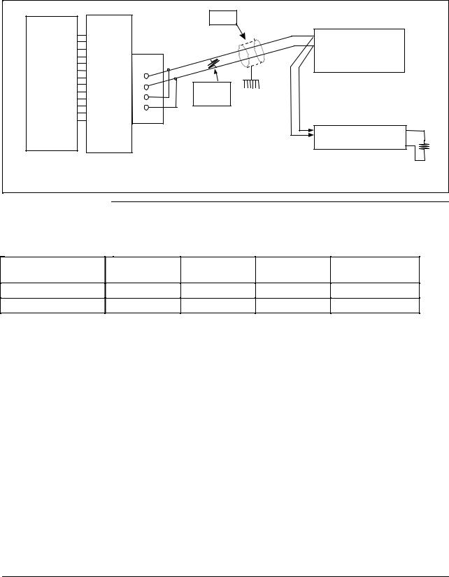
2.3 Using a Black Box Converter, Continued
Black Box wiring connections
Figure 2-1 shows the wiring for the Black Box converter and the devices on the link.
Figure 2-1 |
Black Box Converter Wiring Connections |
|
|
|||
|
|
|
|
Shield |
|
|
|
|
|
|
|
+ |
|
|
|
|
|
|
– |
1ST Device |
|
|
|
|
|
|
on Link |
Computer |
Black Box |
1 |
|
|
|
|
RS232 |
|
|
|
|||
Converter |
2 |
120 Ohm |
|
|
||
output |
|
|
||||
|
|
3 |
Resistor |
|
|
|
|
|
|
|
|
||
|
|
|
4 |
|
|
|
|
|
|
|
|
To other devices on link |
|
|
|
|
|
|
Maximum 16 addresses |
|
|
|
|
|
|
120 ohm resistor between A and B |
|
|
|
|
|
|
on last device on link |
|
|
|
|
|
|
|
22937A |
Link devices terminal |
Table 2-3 lists the terminal connections between the Black Box converter and the |
|||||
connections |
|
devices on the communication link. |
|
|
||
|
|
Table 2-3 |
Terminal Connections for Black Box Converters |
|||
BLACK BOX |
UDC3000 |
UDC6000 |
UDC5000 |
UDC2300 |
||
|
|
UDC3300 |
UDC6300 |
|
|
|
2 |
|
|
15 |
23 |
11 |
14 |
1 |
|
|
14 |
22 |
12 |
13 |
8 |
RS422/485 ASCII Communications Option Product Manual |
5/99 |

2.4Using a Westermo Converter
Wiring the Westermo converter and the link
Figure 2-2 shows the recommended switch setting for the WESTERMO converter.
Figure 2-3 shows the wiring diagram and terminal connections for wiring the RS485 Westermo converter.
Follow the procedure in Table 2-4 to configure and wire the Westermo converter.
Table 2-5 shows the terminal designation for the devices on the link.
Table 2-4 Westermo Converter Configuration and Wiring Procedure
Step |
Action |
|
|
1Install an appropriate Serial Communication Connector between the Computer serial port and the RS232 input connector of the Westermo converter. See the Westermo data sheet for the required interfacing signals.
2Configure the switch settings on the Westermo converter as shown in Figure 2-6.
3Connect the shield to terminal 5. See Figure 2-3.
4Connect one wire to terminal 3 (–).
5Connect other wire to terminal 4 (+).
6Connect a 120 ohm resistor across terminals 3 and 4.
7Create a chain of up to 16 Devices by connecting them with shielded twisted pair wiring (Belden 9271 Twinax or equivalent) to a maximum total length of 4000 feet(1250 meters).
(See Section 13—Cable Specifications.)
REFER TO TABLE 2-5 FOR TERMINAL DESIGNATIONS OF THE DEVICES ON THE LINK
5/99 |
RS422/485 ASCII Communications Option Product Manual |
9 |

2.4 Using a Westermo Converter, Continued
Configuring the
WESTERMO
Converter
Figure 2-2 shows the recommended switch settings for the WESTERMO converter.
Figure 2-2 Recommended Switch Settings for Westermo Converter
S1 |
|
|
|
S3 |
|
S2 |
|
|
|
ON |
|
2 |
|
5 6 |
ON |
1 |
5 |
230 |
|
|
|
|
|
|
|
|
|
OFF |
|
1 |
3 |
4 |
OFF |
2 3 4 |
6 |
|
1 |
2 |
3 |
4 |
5 |
|
|
|
Power |
Line Connection |
V 24/RS-232-C |
|
|||||
Supply |
CONNECTION |
|
||||||
|
|
|
|
|
|
|||
|
|
|
|
|
|
|
|
22933 |
|
|
|
|
|
|
|
|
|
|
|
|
|
|
|
|
|
|
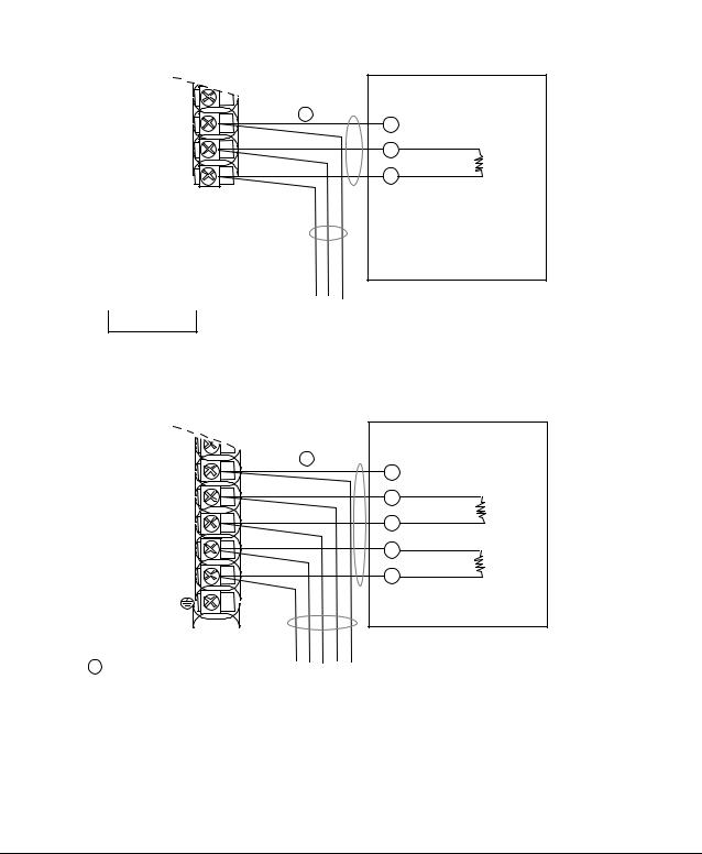
Westermo wiring connections
Figure 2-3 shows the wiring for the Westermo converter and the devices on the link.
Figure 2-3 Westermo Converter Wiring Connections
Computer
RS232
Westermo
output
Converter
+ |
|
– |
1ST Device |
|
on Link |
5 |
|
|
|
4 |
|
|
|
3 |
120 Ohm |
|
|
2 |
|
||
|
|
||
1 |
Resistor |
|
|
|
|
||
|
Shield |
To other devices on link |
|
|
|
Maximum 16 addresses |
|
Twisted pair shield – connect shield |
120 ohm resistor between A and B |
||
on last device on link |
|||
wire with supplied crimp connector |
|||
|
|||
22937
Link devices terminal connections
Table 2-5 shows the terminal connections between the Westermo converter and the devices on the communication link.
Table 2-5 Terminal Connections for Westermo Converters;
Westermo |
|
UDC 3000 |
UDC 5000 |
UDC 6000 |
UDC 2300 |
Line Connections |
|
UDC 3300 |
|
UDC 6300 |
|
3 |
|
15 |
11 |
23 |
14 |
4 |
14 |
12 |
22 |
13 |
|
10 |
RS422/485 ASCII Communications Option Product Manual |
5/99 |
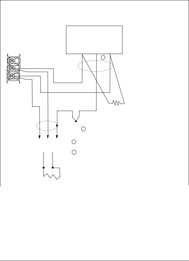
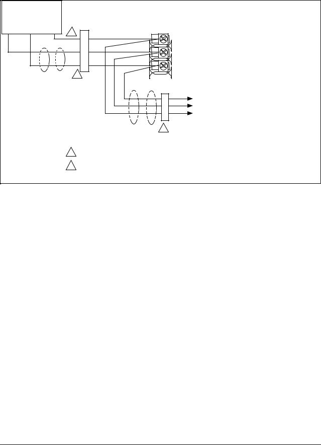
2.5Wiring Diagrams
Communications option Figure 2-4: UDC3000 and UDC3300
connections
Figure 2-5: UDC6000 and UDC6300
Figure 2-6: UDC5000
Figure 2-7: UDC 2300
Figure 2-4 UDC3000/3300 Connections
|
RS422/485 |
|
||
|
HALF DUPLEX |
Master |
||
12 |
|
|
||
SHD |
|
SHD |
||
13 |
1 |
|||
|
|
|||
|
|
TX+/RX+ |
||
14 |
TX+/RX+ |
|
||
TX–/RX– |
|
120 Ohm |
||
15 |
|
TX–/RX– Resistor |
||
|
|
|
||
CAUTION
Do not mix half and full duplex wiring.
To Other |
Do not run these |
Communication |
lines in the same |
Instruments |
conduit as AC power |
(maximum 15) |
120 Ohm Resistor |
|
|
|
on Last Leg |
|
RS422/485 |
|
|
|
|
FULL DUPLEX |
|
Master |
|
12 |
|
|
|
|
|
1 |
SHD |
|
|
13 |
SHD |
|
||
|
|
|||
|
|
TX+ |
|
|
14 |
RX+ |
|
120 Ohm |
|
|
|
TX– |
||
15 |
RX– |
|
Resistor |
|
TX+ |
|
RX+ |
|
|
16 |
|
120 Ohm |
||
TX– |
|
RX– |
||
17 |
|
Resistor |
||
|
|
|||
|
|
|
|
|
1Use shielded twisted pair cables (Belden 9271 Twinax or equivalent)
|
Do not run these |
|
To Other |
|
|
lines in the same |
|
|
Communication |
conduit as AC power |
|
Instruments |
120 Ohm Resistor |
|
(maximum 15) |
|
|
|
on Last Leg |
24169A |
|
5/99 |
RS422/485 ASCII Communications Option Product Manual |
11 |
2.5Wiring Diagrams, Continued
Figure 2-5 UDC6000/6300 Connections
COMMUNICATION MASTER
|
(A) |
(RTN) |
(B) |
|
D+ |
SHLD |
D– |
21 |
|
|
2 |
|
|
|
|
22 |
D+ |
|
|
|
|
|
|
23 |
|
|
|
|
D– |
|
|
120 OHMS
|
|
|
|
|
|
|
|
1 |
|
|
|
|
|
|
|
|
1 Connect shield wires together with Honeywell |
||
TO OTHER |
|
|||
COMMUNICATION |
|
|
supplied crimp part number 30755381-001 |
|
|
2 Do not run these lines in the same conduit as AC power. |
|||
CONTROLLERS |
|
|||
|
|
|
|
|
D– D+
120 OHMS ON LAST LEG |
21758A.ppt |
12 |
RS422/485 ASCII Communications Option Product Manual |
5/99 |
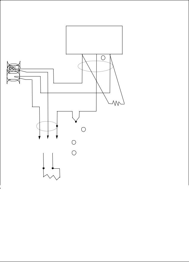
2.5Wiring Diagrams, Continued
Figure 2-6 UDC5000 Connections (without Digital Input Option)
Communication
Master
D+ SHLD D-
1
2
11 |
12 |
13 |
Optional Communication
To Other
Communication
Controllers
4
1Do not run these lines in the same conduit as AC power
2Required for CE Mark Compliance - Kit supplied Part Number
51197612-508 contains 8 Ferrite filters
22330A.ppt
5/99 |
RS422/485 ASCII Communications Option Product Manual |
13 |
2.5Wiring Diagrams, Continued
Figure 2-7 UDC2300 Connections
COMMUNICATION MASTER
(A) |
(RTN) |
(B) |
D+ |
SHLD |
D– |
|
|
2 |
D+
13
14 
D–
120 OHMS
|
|
|
|
|
|
|
|
1 |
|
|
|
|
|
|
|
|
1 Connect shield wires together with Honeywell |
||
TO OTHER |
|
|||
COMMUNICATION |
|
|
supplied crimp part number 30755381-001 |
|
|
2 Do not run these lines in the same conduit as AC power. |
|||
CONTROLLERS |
|
|||
|
|
|
|
|
D– D+
120 OHMS ON LAST LEG |
21758B.ppt |
|
|
14 |
RS422/485 ASCII Communications Option Product Manual |
5/99 |

Section 3 – Establishing Communications and Testing
3.1Preparing the Controller for Communications
Introduction
Synchronization
Configurable parameters
Each controller on the RS422/485 Communications link must be configured at the controller level for certain parameters before communications between the Host and the Controller can be accomplished.
Before you attempt to exchange messages between your computer and the controllers on the RS422/485 link, you must set up the controller for the same form of data transmission that the host computer’s RS422/485 interface uses. This is called Synchronization.
You must match the controller Baud Rate and Parity with that of your computer.
Table 3-1 is a list of parameters that should be configured, their definitions, range of settings or selections, the procedure for entering the information into the controller is found in Table 3-2.
Table 3-1 Communications Parameters
Parameter
Communications
State
Communications
Address
Shed
Shed Time
Duplex
TX Delay
Definition
Enables or disables the Communication function in the controller.
This is a number that is assigned to a controller (limited to 15 controllers) that will be used during communications. This number will be its address on the link (address 0-99).
If your controller has two loops, each loop must have its own individual address (i.e. Loop 1, #6; Loop 2, #7).
Term used to describe a point in time when the controller, which had been working as a slave, reverts to an independent, stand alone controller using its own inputs, configuration data and control mode. Shed will happen when a controller is in slave, the shed is not zero, and the communication stops.
The number selected will represent how many sample periods will elapse before the controller sheds from computer control. Each period equals 1/3 second. 0 = No shed.
Selection made for transmission type. Two-wire transmission is half duplex. Four-wire transmission is full duplex.
Configurable response delay timer allows you to force the UDC to delay its response for a time period of from 1 to 500 milliseconds. Compatible with the host system hardware/software.
5/99 |
RS422/485 ASCII Communications Option Product Manual |
15 |

3.1Preparing the Controller for Communications, Continued
Parameters, continued
Table 3-1 Communications Parameters, Continued
Parameter
Shed Controller
Mode and Output
Level
Shed Setpoint
Recall
Parity
Baud Rate
Communication
Units
Communications
Setpoint Ratio
Communications
Setpoint Bias
Definition
This selection determines the mode of local control whenever the controller is SHED from the slave mode.
•Last Mode and Output – The controller will return to the same mode (Manual or Automatic) and Output level that it was in before shed.
•Manual Mode, Last Output – The controller will return to manual mode and the last output level it was in before shed.
•Manual Mode, Failsafe Output – The controller will return to manual mode at the output level selected at ID code 40 – Failsafe Output Value.
•Shed to Automatic Mode – The controller will return to automatic mode.
This selection determines what setpoint will be used if the controller is shed from the communications link.
•TO LSP – The controller will use the last local setpoint stored.
•TO CSP – The controller will store the last computer setpoint and use it at the Local Setpoint (LSP1, LSP2, or LSP3, whichever is in use).
Transmitting each ASCII character requires 8 bits:
•7 bits for the character code
•1 bit (the eighth) for Parity, which may represent either ODD or EVEN parity.
Thus, the controller can accommodate your computer's choice of parity (odd or even) and perform parity checks on your computer's data transmission. The controller will return STATUS CODE 04 if it detects incorrect parity.
This is the transmission speed in bits per second. In order to communicate properly, the controller must be set to the same Baud Rate as your computer. The Baud Rate selections are: 300, 600, 1200, 2400, 4800, 9600, or 19,200.
This selection determines how the controller values are expressed during communications:
Percent of span or Engineering units.
Ratio value for computer setpoint. The range is from -20.00 to +20.00.
Bias value for computer setpoint. The range is from -999 to 9999.
16 |
RS422/485 ASCII Communications Option Product Manual |
5/99 |
 Loading...