


Wi-Fi Thermostat
9000color touchscreen
Installation Guide
® U.S. Registered Trademark. Patents pending. Copyright © 2016 Honeywell International Inc.
All rights reserved.
HOME. Touch to display Home screen.
FAN. Select fan mode.
SYSTEM. Select system mode (heat/cool).
MENU. Touch to display options. Start here to set a program schedule.
Current schedule. Change temperature setting and select temporary or permanent hold.
Indoor conditions. Shows indoor temperature and humidity.
Current date and time.
Current status. Shows system mode (heat/ cool).
Outdoor conditions. Outdoor temperature and humidity appear after registration.
69-2815EFS-05

Wallplate installation
1.Separate wallplate from thermostat.
2.Mount wallplate as shown below.
Back of
Thermostat
Wallplate
M34500A
Drill 3/16" holes for drywall. Drill 7/32" holes for plaster.
Wire hole
Wall anchors
Mounting screws
|
LEVEL |
|
HERE |
C |
W- |
O/B |
|
K |
Y |
Rc |
G |
R |
W2- |
Aux/E |
|
|
Y2 |
|
L |
Wallplate
CAUTION: ELECTRICAL HAZARD |
M34819 |
|
Can cause electrical shock or equipment damage. Disconnect power before beginning installation.
MERCURY NOTICE
If this product is replacing a control that contains mercury in a sealed tube, do not place the old control in the trash.
69-2815EFS—05 |
2 |
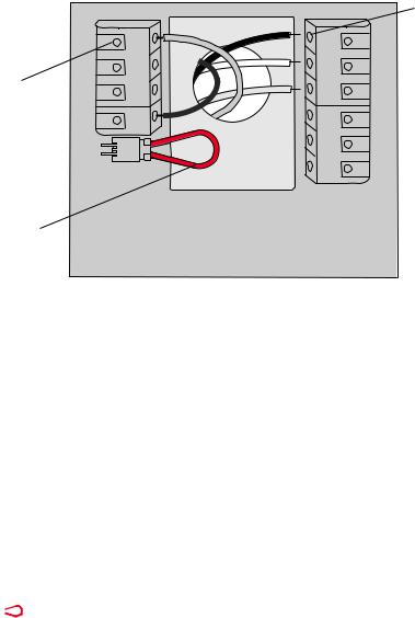
Wiring
|
C |
|
Terminal |
K |
|
Rc |
||
release |
||
|
R |
Remove jumper loop ONLY if you have both
R and Rc wires.
|
Terminal |
|
holes accept |
W- |
one wire |
O/B |
|
Y |
|
G |
|
W2- |
|
Aux/E |
|
Y2 |
|
L |
|
MCR34820
Terminal Designations
|
C |
Common wire from secondary side of cooling transformer (if 2 transformers). |
|
|
K |
Optional wirer save module. |
|
|
Rc |
Cooling power. Connect to secondary side of cooling system transformer. |
|
|
R |
Heating power. Connect to secondary side of heating system transformer. |
|
W-O/B |
1st stage heat relay. Or changeover valve for heat pumps. |
||
|
Y |
1st stage compressor contactor. |
|
|
G |
Fan relay. |
|
W2-Aux/E |
2nd stage heat relay. Or heat pump auxiliary/Emergency heat relay. |
||
|
Y2 |
2nd stage compressor contactor. |
|
|
L |
Heat pump system monitor. |
|
|
|
|
Jumper Loop, a plug with a wire loop used to connect the R to the Rc terminals, |
|
|
|
Leave jumper loop in place in single transformer systems. Remove (unplug) jumper |
|
|
|
loop in two transformer systems. |
3 |
69-2815EFS—05 |

Wiring
Wiring guide — conventional systems
Wiring Instructions
1.This thermostat requires a 24Vac common to power the thermostat. The K terminal is available for Wiresaver module (THP9045A1023).
2.Straighten the wire. Using a pen tip to hold down the terminal, gently slide the wire into terminal hole. Note: Terminal hole will only accept one wire.
1H/1C System |
|
|
|
|
|
|
Cool-only System |
|
|
|
||
(1 transformer) |
|
|
|
|
|
|
|
|
C K Rc R W |
Y G W2 Y2 L |
||
Rc |
Power [1] |
C K Rc R W |
Y G W2 Y2 L |
Rc |
Power [1] |
|||||||
|
|
|
|
|
|
|
|
|
||||
R |
[R+Rc joined by jumper loop] |
|
R |
[R+Rc joined by jumper loop] |
|
|
||||||
Y |
Compressor contactor |
|
|
|
|
Y |
Compressor contactor |
|
|
|||
C |
24VAC common |
|
|
|
|
|
C |
24VAC common |
|
|
||
W |
Heat relay |
|
|
|
|
|
|
G |
Fan relay |
|
|
|
G |
Fan relay |
|
|
|
|
|
|
2H/2C System |
|
|
|
|
|
|
|
|
|
|
|
|
|
|
|
||
Heat-only System |
|
|
|
|
|
|
(1 transformer) |
C K Rc R W |
Y |
G W2 Y2 L |
||
|
|
|
|
|
|
Rc |
Power [1] |
|||||
Rc |
Power [1] |
C |
K Rc |
R |
W |
Y |
G W2 Y2 L |
|
|
MCR34826 |
||
R |
[R+Rc joined by jumper loop] |
|
|
|||||||||
|
|
|
|
|
|
|
|
|||||
R |
[R+Rc joined by jumper loop] |
|
Y |
Compressor contactor (stage 1) |
|
|||||||
C |
24VAC common |
|
|
|
|
|
C |
24VAC common |
|
|
||
W |
Heat relay |
|
|
|
|
|
|
W |
Heat relay (stage 1) |
|
|
|
|
|
|
|
|
|
|
|
G |
Fan relay |
|
|
|
1H/1C System |
|
|
|
|
|
|
W2 |
Heat relay (stage 2) |
|
|
||
|
|
|
|
|
|
Y2 |
Compressor contactor (stage 2) |
|
||||
(2 transformers) |
C |
K Rc |
R |
W |
Y |
G W2 Y2 L |
|
|||||
|
|
|
|
|
||||||||
Rc |
Power (cooling transformer) [1, 2] |
2H/2C System |
|
|
|
|||||||
R |
Power (heating transformer) [1, 2] |
|
|
|
||||||||
Y |
Compressor contactor |
|
|
|
|
(2 transformers) |
C K Rc R W |
Y |
G W2 Y2 L |
|||
C |
24VAC common [3] |
|
|
|
|
Rc |
Power (cooling transformer) [1, 2] |
|||||
W |
Heat relay |
|
|
|
|
|
|
R |
Power (heating transformer) [1, 2] |
|||
G |
Fan relay |
|
|
|
|
|
|
Y |
Compressor contactor (stage 1) |
|
||
Heat-only System |
|
|
|
|
|
|
C |
24VAC common [3] |
|
|
||
|
|
|
|
|
|
W |
Heat relay (stage 1) |
|
|
|||
with Fan |
|
|
|
|
|
|
G |
Fan relay |
|
|
|
|
Rc |
Power [1] |
C |
K Rc |
R |
W |
Y |
G W2 Y2 L |
W2 |
Heat relay (stage 2) |
|
|
|
R |
[R+Rc joined by jumper loop] |
MCR34824 |
Y2 |
Compressor contactor (stage 2) |
|
|||||||
|
|
|||||||||||
C |
24VAC common |
|
|
|
|
|
|
|
|
|
|
|
W |
Heat relay |
|
|
|
|
|
|
See [notes] below |
|
|
|
|
G |
Fan relay |
|
|
|
|
|
|
|
|
|
|
|
Jumper Loop
NOTES
Wire specifications:
Use 18to 22-gauge thermostat wire.
Shielded cable is not required.
[1]Power supply. Provide disconnect means and overload protection as required.
[2]Remove jumper loop for 2-transformer systems.
[3]Common connection must come from cooling transformer.
69-2815EFS—05 |
4 |

Wiring
Wiring guide — heat pump systems
Wiring Instructions
1.This thermostat requires a 24Vac common to power the thermostat. The K terminal is available for Wiresaver module (THP9045A1023).
2.Straighten the wire. Using a pen tip to hold down the terminal, gently slide the wire into terminal hole. Note: Terminal hole will only accept one wire.
1H/1C Heat |
|
|
|
|
||
Pump System |
|
|
|
|
||
Rc |
Power [1] |
C K Rc |
R O/B |
Y |
G W2 Y2 L |
|
R |
[R+Rc joined by jumper loop] |
|
||||
Y |
Compressor contactor |
|
|
|
||
C |
24VAC common |
|
|
|
||
O/B |
Changeover valve [7] |
|
|
|
||
G |
Fan relay |
|
|
|
|
|
2H/1C Heat |
|
|
|
|
||
Pump System |
C K Rc |
R O/B |
Y |
G Aux/E Y2 L |
||
Rc |
Power [1] |
|||||
|
|
|
MCR34829 |
|||
R |
[R+Rc joined by jumper loop] |
|
||||
Y |
Compressor contactor |
|
|
|
||
C |
24VAC common |
|
|
|
||
O/B |
Changeover valve [2] |
|
|
|
||
G |
Fan relay |
|
|
|
|
|
Aux/E |
Auxiliary/Emergency heat relay |
|||||
L |
Heat pump system monitor |
|
|
|||
3H/2C Heat Pump System
Rc Power [1]
R [R+Rc joined by jumper loop] Y Compressor contactor (stage 1) C 24VAC common
O/B Changeover valve [2] G Fan relay
Aux/E Auxiliary/Emergency heat relay Y2 Compressor contactor (stage 2) L Heat pump system monitor
See [notes] below
Jumper Loop
NOTES
Wire specifications:
Use 18to 22-gauge thermostat wire. Shielded cable is not required.
[1]Power supply. Provide disconnect means and overload protection as required.
[2]In Setup, set changeover valve to O or B.
5 |
69-2815EFS—05 |
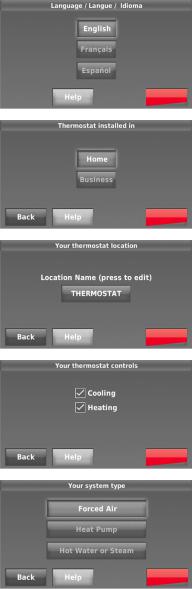
Initial setup
Upon initial power up, or after being reset to factory defaults, the initial thermostat options (language, location, and system type) must be set to define the heating/cooling system. Other options can be customized later.
Follow prompts on the screen to select appropriate options.
1.Touch the language you want the thermostat to display, then touch Next.
2.Select Home or Business installation, then touch Next.
3.Touch Next, or name the thermostat location—touch THERMOSTAT and follow the rest of the instructions.
4.Select what the thermostat will control and touch Next.
Note: Touch the orange Help button on any screen for more information.
5.Select the system type and touch Next. The system type determines other selections for completing initial setup.
6.Touch Next after making selections on each screen.
7.Touch Done on the last screen. The thermostat displays an option to connect to the Wi-Fi network.
Next
Next
Next
Next
Next
69-2815EFS—05 |
6 |
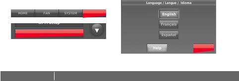
System setup
From the home screen, touch Menu > System Setup to modify the initial system setup.
|
MENU |
|
System Setup |
||
|
Next |
|
System Setup Options (MENU > System Setup) |
||
|
|
|
Screen Title |
Settings and Options |
|
|
|
|
Language |
English/Français/Español. |
|
|
|
|
Thermostat installed |
Home/Business (Thermostat is used in a residential (default) or commercial |
|
in |
setting). |
|
|
|
|
Your thermostat |
Touch THERMOSTAT button to display a screen where you can enter a custom |
|
name using a keypad. If you have only one thermostat, you can leave the |
||
location |
name as THERMOSTAT. For business installations you can check a box to |
|
|
display the thermostat name on the home screen. |
|
|
|
|
Your thermostat |
Select Heating or Cooling or both (default). |
|
controls |
||
|
||
|
|
|
Your system type |
Select Forced Air (default), Heat Pump, or Hot Water or Steam. Each option |
|
offers different choices on the following screens. |
||
|
||
|
|
|
Your forced air |
Select how your forced air system is powered: Gas/Oil (default) or Electric. |
|
heating system type |
||
|
||
|
|
|
Efficiency of your |
Select Standard Efficiency Forced Air (default) or High Efficiency Forced Air. |
|
heating system |
||
|
||
Your heating system |
If you selected Hot Water or Steam on “Your system type,” select the specific |
|
type |
heating system here. |
|
|
|
|
Number of cooling |
Select 1 Stage (default) or 2 Stages. If you are unsure, note which wires are |
|
stages |
connected: ‘Y’ wire only (1 stage) or ‘Y’ and ‘Y2’. |
|
|
|
|
Number of heating |
Select 1 Stage (default) or 2 Stages. If you are unsure, note which wires are |
|
stages |
connected: ‘W’ wire only (1 stage) or ‘W’ and ‘W2’. |
|
|
|
|
Your fan control |
Select whether your thermostat (default) or heating system controls the fan. |
|
|
|
|
Type of changeover |
If you selected Heat Pump on “Your system type,“ select whether it uses a |
|
valve |
cooling changeover valve (default) or heating changeover valve. |
|
|
|
|
Number of heat |
Select 1 Stage (default) or 2 Stages. If you are unsure, note which wires are |
|
pump compressor |
||
connected: ‘Y’ wire only (1 stage) or ‘Y’ and ‘Y2’. |
||
stages |
||
|
||
|
|
|
Your backup heat |
No or Yes (default) |
|
|
|
|
7 |
69-2815EFS—05 |

Connecting to the Wi-Fi network
After the initial setup, walk the homeowner through connecting to a Wi-Fi network. Or, refer the homeowner to the User’s Guide, so the homeowner can connect the thermostat to a Wi-Fi network at a later time.
1 Connect the Wi-Fi network.
Touch Yes to connect the thermostat to the Wi-Fi network. The screen displays the message “Searching for wireless networks. Please wait...” after which it displays a list of all Wi-Fi networks it can find.
Note: If you cannot complete this step now, touch I’ll do it later. The thermostat will display the home screen. Complete this process by selecting MENU > Wi-Fi Setup. Continue with Step 2.
2 Select the network.
2a Touch the name of the homeowner’s network. The thermostat displays a password page.
Note: If the home network is not shown on the list, touch Rescan.
2b Using the keyboard, touch the characters that spell out the home network password.
2c Touch Done. The thermostat displays “Connecting to your network. Please wait...” then shows a “Connection Successful” screen.
2d Touch Next to display the registration information screen.
2e Have the homeowner register the thermostat by going to http://www.mytotalconnectcomfort.com Note the Thermostat MAC and CRC; they’ll be needed during registration. Or, refer the homeowner to the User’s Guide.
Note: The Register Online screen remains active until you complete registration and/or touch Done.
3For remote access, the homeowner or enduser must register at mytotalconnectcomfort.com
Yes
Your Network
Register online for remote access
Press for info
Done
Next
Done
69-2815EFS—05 |
8 |

Setting advanced preferences
1Touch MENU. The thermostat displays a list of options.
2Select Preferences > Advanced Preferences. The thermostat displays the first screen of options that you can change.
3On each screen, make changes as needed, then touch Next to display new options. Repeat this step until you have made all changes.
4When you have made all changes, press Done to save and exit.
MENU
Preferences
Advanced Preferences
Next
Screen Title |
Settings and Options |
|
|
|
|
|
Select Non-programmable or Programmable. Programmable uses |
|
Scheduling Options |
default or customized programming to automatically raise and lower |
|
|
temperature settings for different times of day. |
|
Temperature Indication |
Select Fahrenheit or Celsius. |
|
Scale |
||
|
||
Heating and Cooling System |
Select Manual or Automatic. |
|
Changeover |
|
|
Number of Schedule Periods |
Select 2 Periods Per Day or 4 Periods Per Day. |
|
Pre-occupancy Purge |
Select how long the fan will run before each occupied period: Off, 1, |
|
Duration * |
2, or 3 hours. |
|
|
Select Standard to maintain the programmed periods or Initiate |
|
Type of Override * |
Occupancy to use energy-saving settings until a user presses Start |
|
|
Occupancy. |
|
Override Duration * |
Select how long to maintain temperature during an override: 1-10 |
|
hours or No Limit. |
||
|
||
Early Recovery for Heating * |
Select No to begin recovery on schedule or Yes to ramp up |
|
temperature early. |
||
Early Recovery for Cooling * |
Select No to begin recovery on schedule or Yes to ramp down |
|
temperature early. |
||
Temperature Limits |
Select the Minimum Cool and Maximum Heat Limit. |
|
Keypad Lockout |
Select Unlocked/Partially Locked/Locked. |
|
Clock Format |
Select 12 Hour or 24 Hour. |
|
Daylight Saving Time |
Select Off or On. If set to On, the system will automatically change |
|
time/date to account for daylight saving. |
||
|
||
Indoor Display Offsets |
Select the number of degrees to offset indoor temperature or |
|
percentage to offset indoor humidity. |
||
|
*Available when thermostat is installed in Business mode.
9 |
69-2815EFS—05 |
Troubleshooting
If you have difficulty with your thermostat, please try the following suggestions. Most problems can be corrected quickly and easily.
Display is blank
•Check circuit breaker and reset if necessary.
•Make sure power switch at heating and cooling system is on.
•Make sure furnace door is closed securely.
•Make sure C wire is connected.
Cannot change system setting to Cool
Fan does not turn on when heat is required
•Check that System Setup screen “Your thermostat controls” or “Your system type” is set to match your heating and cooling equipment.
•Check that System Setup screen “Your fan control” is set to match your heating equipment.
“Wait” appears on the screen
Heat pump issues cool air in heat mode, or warm air in cool mode
•Compressor protection feature is engaged. Wait 5 minutes for the system to restart safely, without damage to the compressor.
•Check your setting for System Setup screen “Type of changeover valve” to make sure it is properly configured for your system (see page <?>).
Heating or cooling system does not respond
Heating system is running in cool mode
• |
Touch SYSTEM to set system to Heat. Make sure the temperature is set |
|
higher than the Inside temperature. |
• |
Touch SYSTEM to set system to Cool. Make sure the temperature is set |
|
lower than the Inside temperature. |
• |
Check circuit breaker and reset if necessary. |
• |
Make sure power switch at heating and cooling system is on. |
• |
Make sure furnace door is closed securely. |
• |
If “Wait” is displayed, the compressor protection timer is on. Wait 5 minutes |
|
for the system to restart safely, without damaging the compressor. |
• |
Check that System Setup screen “Your thermostat controls” or “Your system |
|
type” is set to match your heating and cooling equipment . |
69-2815EFS—05 |
10 |
Accessories & replacement parts
Please contact your distributor to order replacement parts.
Cover plate assembly. . . . . . . . . Part Number THP2400A1027W
Specifications
Temperature Ranges
•Heat: 40° to 90°F (4.5° to 32°C)
•Cool: 50° to 99°F (10° to 37°C)
Operating Ambient Temperature
• 32° to 120°F (0° to 48.9°C)
Shipping Temperature
• -20° to 120°F (-28.9° to 48.9°C)
Operating Relative Humidity
• 5% to 90% (non-condensing)
Physical Dimensions
•4-1/2" W x 3-1/2" H x 7/8” D
115 mm W x 88 mm H x 22 mm D
Electrical Ratings |
|
|
Terminal |
Voltage |
Max. Current |
|
(50/60Hz) |
Rating |
W-O/B |
20-30 Vac |
1.0 A |
W2 (Aux/E) |
20-30 Vac |
1.0 A |
Y Cooling |
20-30 Vac |
1.0 A |
Y2 Cooling |
20-30 Vac |
1.0 A |
G Fan |
20-30 Vac |
0.5 A |
11 |
69-2815EFS—05 |
 Loading...