


T87F
Table of contents
 Loading...
® U.S. Registered Trademark
Copyright © 2002 Honeywell • • All Rights Reserved
INSTALLATION INSTRUCTIONS
69-0200-6
T87F
Easy-to-See™ Thermostats
APPLICATION
The Easy-to-See™ 24 Vac Thermostats are:
The thermostat features a raised setpoint knob for easy
adjustment, a cover ring with large embossed numbers
for easy reading and an audible click with indents every
two degrees as the dial is turned.
MERCURY NOTICE
If this control is replacing a control that contains
mercury in a sealed tube, do not place your old
control in the trash. Dispose of properly.
Contact your local waste management authority
for instructions regarding recycling and the
proper disposal of an old control.
INSTALLATION
When Installing this Product. . .
1. Read these instructions carefully. Failure to follow
them could cause a hazardous condition.
2. Check the ratings given in the instructions and on
the product to make sure the product is suitable for
your application.
3. Installer must be a trained experienced service
technician.
4. After installation is complete, check out product
operation as provided in these instructions.
CAUTION
1. Disconnect power supply to prevent electrical
shock or equipment damage.
2. To prevent interference with the thermostat
linkage, keep wire length to a minimum and
run wires as close as possible to the subbase.
3. Do not overtighten thermostat captive
mounting screws, because damage to
subbase threads can result.
4. Do not short across coil terminals on relay.
This can burn out the thermostat heat
anticipator.
IMPORTANT
An incorrectly leveled thermostat can cause the
temperature control to deviate from setpoint.
Location
Install the thermostat between 4 ft (1.2m) and 5 ft (1.5m)
above the floor. Locate in an area with good air circula-
tion at average temperature.
NOTE: Due to the height restrictions of some disabled
users, it may be necessary to lower the thermo-
stat location to 4 ft (1.2m) above the floor.
Do not install the thermostat where it can be affected by:
— drafts, or dead spots behind doors and in corners.
— hot or cold air from ducts.
— radiant heat from sun or appliances.
— concealed pipes and chimneys.
— unheated (uncooled) areas such as an outside wall
behind the thermostat.
This thermostat is a precision instrument and was
carefully adjusted at the factory. Handle it carefully.
Mount Wallplate or Subbase
IMPORTANT
When using the thermostat with a Q539 Sub-
base, follow the mounting and wiring instruc-
tions furnished with the subbase.
NOTE: To mount the thermostat on an outlet box, order
129044A Adapter Ring Assembly.
Model Application Includes
T87F
Heating or
Heating/Cooling
a
a
For heating/cooling, order the Q539 Subbase, which
provides System and Fan switches at the thermostat
location.
T87F3467/T87F5199
Thermostats and
137421A Wallplate.
T87F EASY-TO-SEE™ THERMOSTATS
69-0200-6 2
1. Hold wallplate in position and mark holes for
anchors. See Fig. 1. Obtain wall anchors locally.
Be careful that the wires do not fall back into the
wall opening. Set aside the wallplate. Drill four
3/16 in. (4.6 mm) holes and gently tap anchors into
the holes until flush with the wall.
2. Pull electrical wires through the wallplate opening.
See Fig. 1.
3. Secure the wallplate with the screws provided. Do
not fully tighten the screws.
4. Level the wallplate using a spirit level. See Fig. 1.
Firmly tighten the mounting screws. The mounting
holes provide for minor out-of-level adjustments.
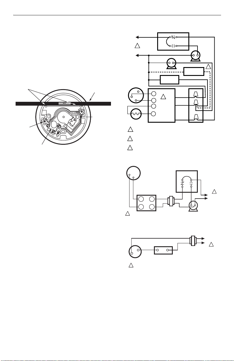
Fig. 1. Level wallplate before mounting thermostat.
Wiring
All wiring must comply with local electrical codes and
ordinances. Follow equipment manufacturer ’s wiring
instructions when available.
The thermostat is adaptable to most two-wire and three-
wire (series 10 spdt) 24 Vac to 27 Vac heating systems.
To wire wallplate, proceed as follows:
1. Connect the system wires to the wallplate as
shown in Fig. 2 through 6. A letter code is near
each terminal for identification.
2. Firmly tighten each terminal screw.
3. Fit wires as close as possible to the wallplate. Push
excess wire back into hole.
4. Plug hole with nonflammable insulation to prevent
drafts from affecting the thermostat.
Fig. 2. Typical oil heating system.
Fig. 3. Typical gas heating system.
Fig. 4. Typical cooling only system.
Note that R and Y terminals are used.
SPIRIT
LEVEL
MOUNTING
SLOT (3)
M394B
MOUNTING
HOLE (3)
137421K WALLPLATE
OPENING FOR
THERMOSTAT
WIRING (PLUG)t
(WITH INSULATION)
MOLDED
POST (2)
L2
COMBINATION FAN
AND LIMIT CONTROL
FAN
MOTOR
BURNER
MOTOR
THERMOSTAT
Y
R
W
CAD CELL
1
2
3
R8184G
WHITE
ORANGE
BLACK
IGNITION
OIL VALVE
POWER SUPPLY. PROVIDE DISCONNECT MEANS AND
OVERLOAD PROTECTION AS REQUIRED.
R8184 PROTECTORELAY OIL PRIMARY CONTAINS
INTERNAL TRANSFORMER
CONNECT OIL VALVE, IF APPLICABLE.
2
1
T
F
M6105
A
T
F
L1
(HOT)
3
R
W
1
L1
(HOT
)
L2
FAN
MOTOR
COMBINATION FAN AND
LIGHT CONTROLLER
LIMIT
FAN
TRANSFORMER
GAS VALVE
THERMOSTAT
TH
TH
TR
TR
M6103
1
POWER SUPPLY. PROVIDE DISCONNECT MEANS AND
OVERLOAD PROTECTION AS REQUIRED.
1
L1
(HOT
)
L2
1
THERMOSTAT
COOLING
CONTACTOR COIL
POWER SUPPLY. PROVIDE DISCONNECT MEANS AND
OVERLOAD PROTECTION AS REQUIRED.
M610
1
R
Y
Loading...