


 Loading...
Installation and Operations Guide
TB3026B, TB3026B-W
31-00098-01
© Honeywell |
31-00098-01 |
Important safety information and installation precautions
Read all instructions
Failure to follow all instructions may result in equipment damage or a hazardous condition. Read all instructions carefully before installing equipment.
Local codes and practices
Always install equipment in accordance with the National Electric Code and in a manner acceptable to the local authority having jurisdiction.
Electrostatic sensitivity
This product and its components may be susceptible to electrostatic discharge (ESD). Use appropriate ESD grounding techniques while handling the product. When possible, always handle the product by its non-electrical components.
High voltage safety test
Experienced electricians, at first contact, always assume that hazardous voltages may exist in any wiring system. A safety check using a known, reliable voltage measurement or detection device should be made immediately before starting work and when work resumes.
Lightning and high-voltage danger
Most electrical injuries involving low-voltage wiring result from sudden, unexpected high voltages on normally low-voltage wiring. Low-voltage wiring can carry hazardous high voltages under unsafe conditions. Never install or connect wiring or equipment during electrical storms. Improperly protected wiring can carry a fatal lightning surge for many miles. All outdoor wiring must be equipped with properly grounded and listed signal circuit
!while standing in water.
Wiring and equipment separations
All wiring and controllers must be installed to minimize the possibility of accidental contact with other potentially hazardous and disruptive power and lighting wiring. Never place 24VAC or communications wiring near other bare power wires, lightning rods, antennas, transformers, or steam or hot water pipes. Never place wire in any conduit, box, channel, duct or other enclosure containing power or lighting circuits of any type. Always provide adequate separation of communications wiring and other electrical wiring according to code. Keep wiring and controllers at least six feet from large inductive loads (power distribution panels, lighting ballasts, motors, etc.). Failure to follow these guidelines can introduce electrical interference and cause the system to operate erratically.
Warning
This equipment has been tested and found to comply with the limits for a class A digital device, pursuant to part 15 of the FCC rules. These limits are designed to provide reasonable protection against harmful interference when the equipment is operated in a commercial environment. This equipment generates, uses, and can radiate radio frequency energy and, if not installed and used in accordance with the instruction manual, may cause
harmful interference to radio communications. Operation of this equipment in a residential area is likely to cause harmful interference, in which case the user will be required to correct the interference at his own expense.protectors, which must be installed in compliance with local, applicable codes. Never install wiring or equipment
© 2016 Honeywell. All Rights Reserved. 1985 Douglas Drive North
Golden Valley, MN 55422 customer.honeywell.com
By using this Honeywell literature, you agree that Honeywell will have no liability for any damages arising out of your use, or modification to, the literature. You will defend and indemnify Honeywell, its affiliates and subsidiaries, from and against any liability, cost, or damages, including attorneys’ fees, arising out of, or resulting from, any modification to the literature by you.
Questions, corrections, or comments?
To improve our information products and better serve our readers, your feedback is vital. If you have any questions, corrections, or comments about this publication or any other information products, please send e-mail to WEBsSquad@honeywell.com.
2 |
31-00098-01 |
© Honeywell |

Installation and Operations Guide | Contents
Contents
About the BACnet FF |
4 |
About this document and related publications |
5 |
BACnet FF dimensions |
6 |
Mounting guidelines |
7 |
Installing the wallplate |
7 |
Wiring the wallplate |
8 |
Mounting the BACnet FF faceplate |
9 |
Mounting a door/window sensor |
9 |
Mounting a PIR occupancy motion sensor |
11 |
Terminals and wiring |
12 |
Power supply guidelines and requirements |
14 |
BACnet FF power ratings |
14 |
Selecting a transformer |
14 |
Power supply grounding and wiring |
14 |
Backup power |
15 |
MS/TP LAN Wiring |
16 |
Terminating MS/TP LAN cabling |
16 |
Grounding the MS/TP LAN shield |
17 |
Terminating resistors |
17 |
Configuration |
18 |
Adjusting the date and time |
18 |
Setting the MAC address and device instance |
18 |
Installer setup (ISU) codes |
20 |
Pairing a sensor to a wireless BACnet FF |
22 |
Fixed field service codes |
24 |
Operational overview |
25 |
Configuring a DDCMULTI application |
27 |
Application Sequences and Configuration Settings |
28 |
[AP] 0: Air-to-air heat pump |
29 |
[AP] 1: Water-source heat pump |
29 |
[AP] 2: Air-to-air heat pump |
46 |
[AP] 3: Water source heat pump |
46 |
[AP] 4: Air Conditioning Unit |
63 |
[AP] 5: Air Conditioning Unit |
79 |
[AP] 6: 4 Pipe Fan Coil Unit |
96 |
[AP] 7: 4 Pipe Fan Coil Unit |
112 |
[AP] 8: 4 Pipe Fan Coil Unit |
128 |
[AP] 9: 4 Pipe Fan Coil Unit |
146 |
[AP] 10: Air to Air Heat Pump |
164 |
[AP] 11: 2 Pipe Fan Coil Unit |
183 |
[AP] 12: 2 Pipe Fan Coil Unit |
201 |
[AP] 13: 2 Pipe Fan Coil Unit with Change Over Control |
219 |
[AP] 14: 2 Pipe Fan Coil Unit with Change Over Control |
237 |
[AP] 15: 2 Pipe Fan Coil Unit |
255 |
[AP] 16: 2 Pipe Fan Coil Unit with Change Over Control |
272 |
[AP] 17: 4 Pipe Fan Coil Unit |
290 |
[AP] 18: 2 Pipe Fan Coil Unit with Change Over Control |
309 |
Appendix A: BACnet object and property reference |
327 |
Appendix B: Ordered list of control points |
343 |
Appendix C: Quick reference |
347 |
Appendix D: Canadian conformance statements |
348 |
© Honeywell |
31-00098-01 |
3 |
Installation and Operations Guide | BACnet FF
About the BACnet FF
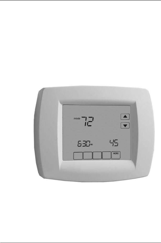
The Honeywell BACnet FF (models TB3026B and TB3026B-W) is a communicating sensor/fixed application controller with built-in humidity sensor. The TB3026B-W is the wireless version with an onboard wireless receiver for wireless occupancy control.
Electrical inputs and outputs wire directly to field equipment. The BACnet FF comes pre-loaded with nineteen applications that support common uses. These applications can be selected and some of the parameters adjusted at the controller without the need for a BACnet front end.
Operational information and control data is available to other building controllers and systems through the BACnet protocol (ANSI/ASHRAE standard). This enables a BACnet FF to share data and execute commands initiated from other BACnet-compliant devices.
4 |
31-00098-01 |
© Honeywell |

Installation and Operations Guide | About this document and related publications
About this document and related publications
This document provides information about installing and wiring a BACnet FF to equipment, power, and communication channels. It also shows how to operate the user interface.
IMPORTANT Always install equipment in accordance with the National Electric Code and in a manner acceptable to the local authority having jurisdiction (AHJ). No guidelines, instructions, installation practices, or other information presented in this guide may be interpreted to supersede or modify the local codes and practices of the AHJ.
Table 1 Other documentation related to BACnet FFs
Document (ID) |
Contains |
Installation Instructions (31-00093) |
Instructions on how to install, wire |
|
and perform initial configuration for |
|
the BACnet FF |
|
|
Product Data |
Summary of capabilities and |
(31-00096) |
specifications |
|
|
WEBs-AX Configuration Wizard Guide |
Instructions on how to configure the |
(31-00097) |
BACnet FF through the WEBs based |
|
wizard |
|
|
© Honeywell |
31-00098-01 |
5 |
Installation and Operations Guide | BACnet FF
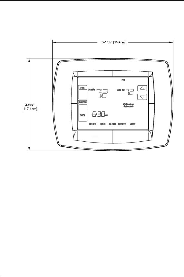
BACnet FF dimensions
The BACnet FF consists of a mounting plate and a circuit board with a plastic cover. See the BACnet FF Installation Instructions (31-00093) for more information.
Figure 1 TB3026B and TB3026B-W dimensions
6 |
31-00098-01 |
© Honeywell |
Installation and Operations Guide | Mounting guidelines
Mounting guidelines
The BACnet FF is designed to be wall-mounted indoors, with dimensions ideal for mounting to a single-gang electrical box.
Mount in a clean, dry location away from windows, air ducts, and other places where environmental factors may affect temperature and humidity readings. If you mount the BACnet FF on the interior of an outside wall, thoroughly insulate so outside air behind the sensor does not affect the sensor reading.
To meet requirements of the Americans with Disabilities Act, mount no higher than 48" from the floor and with a minimum clear floor space of 30" X 48" (760 X 1220 mm).
CAUTION Thoroughly read all instructions before mounting and wiring. Always install equipment in accordance with applicable electric codes and the instructions.
Installing the wallplate
The BACnet FF can be mounted horizontally on the wall or on a 4 in. x 2 in. (101.6 mm x 50.8 mm) wiring box.
To install the wallplate
1.Position and level the wallplate (for appearance only).
2.Use a pencil to mark the mounting holes.
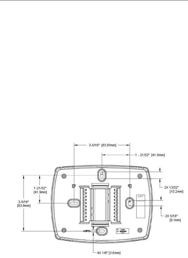
Figure 2 Wallplate dimensions
3.Remove the wallplate from the wall and, if drywall, drill two 3/16-in. holes in the wall, as marked. For firmer material such as plaster, drill
© Honeywell |
31-00098-01 |
7 |
Installation and Operations Guide | BACnet FF
two 7/32-in. holes. Gently tap anchors (provided) into the drilled holes until flush with the wall.
4.Position the wallplate over the holes, pulling wires through the wiring opening.
5.Insert the mounting screws into the holes and tighten.
Wiring the wallplate
CAUTION Disconnect power before wiring. Failure to do so may result in electrical shock or equipment damage.
To wire the wallplate
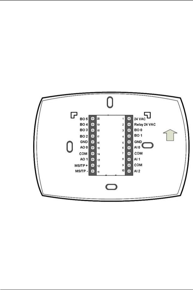
1. Connect wires to the terminal block using Figure 3 as a guide.
Figure 3 Terminal assignments and pin numbers
2.Securely tighten each screw.
3.Push excess wire back into the hole.
4.Plug the hole with nonflammable insulation to prevent drafts from affecting the BACnet FF.
Note A jumper is pre-installed between pins 1 and 2 (24 VAC and Relay 24 VAC). This supplies 24 VAC to BO 1, BO 3, and BO 4. It can be removed if you want to power these inputs from a separate power supply.
8 |
31-00098-01 |
© Honeywell |
Installation and Operations Guide | Mounting guidelines
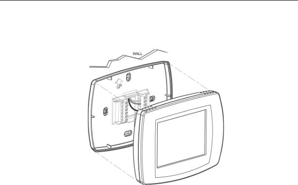
Mounting the BACnet FF faceplate
To mount the BACnet FF faceplate, align the terminal blocks with the pins on the back of the BACnet FF and push the faceplate straight onto the wallplate.
Figure 4 BACnet FF faceplate mounting
Mounting a door/window sensor
These instructions apply to the primary door sensor and an optional second door/window sensor, WSK-24.
Note The BACnet FF supports a maximum of 8 door/window sensors.
To mount a door sensor
1.Remove the battery tab.
Note Completely remove the battery tab or the BACnet FF will not operate.
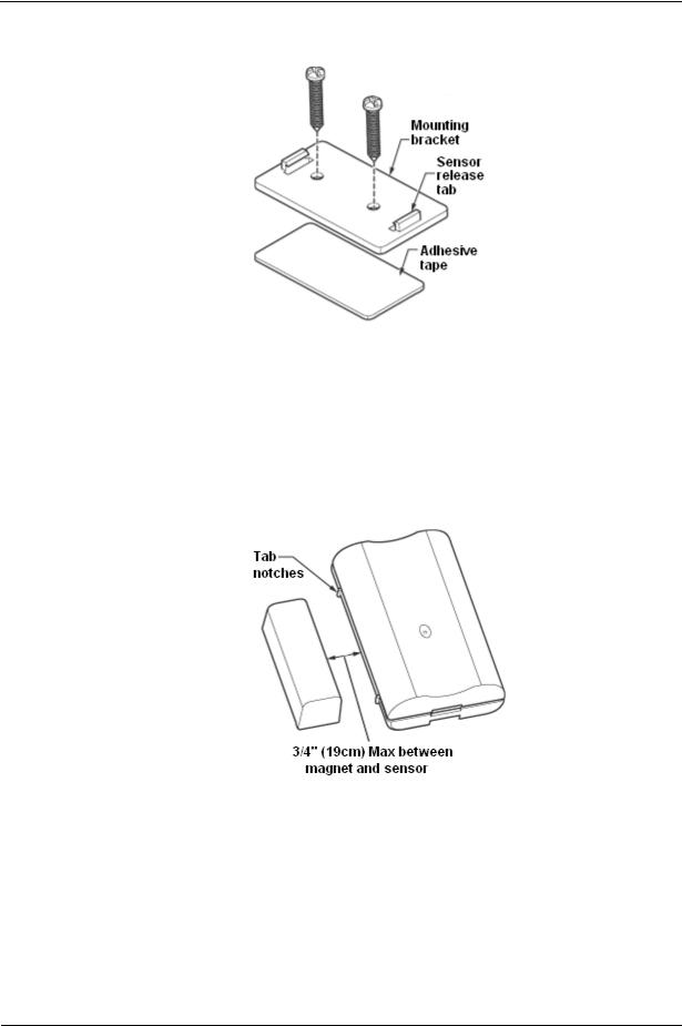
2.Remove the plastic mounting bracket from the door sensor housing.
3.Place the mounting bracket for the door sensor high on the frame of the door. Secure the bracket to the door frame using the two screws or adhesive tape provided.
© Honeywell |
31-00098-01 |
9 |
Installation and Operations Guide | BACnet FF
4.Door sensor bracket mounting
5.Make sure the notched side of the door sensor is pointing in the direction that you will mount the magnet.
6.Snap the sensor into the mounting bracket.
7.Align one end of the magnet with the notched side of the door sensor housing.
8.Mount the magnet a maximum of 3/4 in. (19 mm) from the door sensor.
Figure 5 Maximum distance between door sensor and magnet
9.Secure the magnet to the door by using the two screws or adhesive tape provided. An optional spacer is provided.
10.Open and close the door to ensure that there is no interference.
10 |
31-00098-01 |
© Honeywell |
Installation and Operations Guide | Mounting guidelines
Mounting a PIR occupancy motion sensor
Note The BACnet FF supports a maximum of 3 passive infrared (PIR) sensors.
To mount a PIR motion sensor
1.Take off the cover by removing the cover release screw on the bottom of the PIR backplate.
Figure 6 PIR occupancy motion sensor mounting options
2.Insert three AAA batteries.
3.Secure the PIR sensor to the wall using one of the following options:
•Wall Mount option 1: Use adhesive tape to secure the PIR backplate to the wall.
•Wall mount option 2: Using either the top or bottom two holes of the PIR backplate, insert the two long screws to secure the PIR backplate to the wall.
•Ceiling mount option: Align the mounting bracket and PIR backplate. Insert the two small screws into the top holes of the backplate and secure it to the bracket. Use the two long screws (and, if necessary, the optional plastic anchors) to mount the bracket and PIR backplate to the ceiling.
4.Replace the PIR sensor cover and cover release screw.
© Honeywell |
31-00098-01 |
11 |

Installation and Operations Guide | BACnet FF
Terminals and wiring
The BACnet FF label identifies wiring terminals by number and function. Terminals are numbered from top to bottom, beginning with 1 on the upper right side of the wallplate and continuing top-to-bottom on the right side of the controller. I/O terminals carry an additional numeric identifier that corresponds to the software I/O. Use this section to identify terminals on the BACnet FF. See later sections for more specific instructions, cautions, and recommendations.
Power supply terminals
Use terminals 1 and 5 to connect the 24VAC power supply to the BACnet FF.
Ground terminals
These terminals are used for terminating the grounded leg of the 24VAC circuit and the return grounds of BOs.
COM terminals
These terminals are used for terminating the return grounds of AIs and AOs.
Universal inputs (AIs)
Use these terminals (in conjunction with adjacent GND terminals) to connect universal inputs. Input terminals accept a variety of signal types.
Binary outputs (BOs)
Use these terminals to connect BO loads (ON/OFF control). Terminate the BO return ground to the panel/enclosure ground or a GND terminal on the BACnet FF.
WARNING! Do not apply line voltage to source pins.
Analog outputs (AOs)
Use these terminals to connect AO-loads (modulating control). The AO-return ground must terminate to the nearest GND terminal.
MS/TP LAN terminals
Use terminals 11(MS/TP-) and 12 (MS/TP+) to connect the BACnet MS/TP LAN to the BACnet FF. Maintain polarity throughout the entire LAN. See “MS/TP LAN Wiring” on page 16 for more information.
12 |
31-00098-01 |
© Honeywell |

Installation and Operations Guide | Terminals and wiring
Using terminal blocks
The BACnet FF uses header-style termination blocks to simplify field wiring of power, communications, and I/Os. Terminal blocks accept wire gage from 12–24AWG.
To terminate wire to a BACnet FF
1.Strip approximately 1/8” of the wire jacket from the end of the wire.
2.Use a small screwdriver (1/8” max) to turn the adjustment screw fully counter-clockwise. The clamps in the wire slot separate as you turn the screw.
3.Insert the stripped end of the wire into it (try to get the jacket flush with the terminal block). If using stranded wire, be sure to insert all strands into the wire slot. If terminating multiple wires, trim wires to same length and tightly twist exposed wire together.
4.Hold the wire in place and turn the adjustment screw clockwise to tighten it until the clamps in the wire slot secure the wire.
5.Tug gently on the wire to ensure it is secure.
© Honeywell |
31-00098-01 |
13 |

Installation and Operations Guide | BACnet FF
Power supply guidelines and requirements
BACnet FF uses 24VAC power from a UL Listed Class 2 24VAC transformer (not provided). The BACnet FF uses a half-wave rectifier to convert the AC power supply to onboard power. This enables multiple BACnet FFs with half-wave power supplies to be powered from a single, grounded transformer.
CAUTION Half-wave devices and full-wave devices must not use the same AC transformer. If a BACnet FF will share its power supply with another device, make sure that the other device utilizes a half-wave rectifier and that polarity of wiring is maintained. Failure to do so can result in equipment damage.
Figure 7 Internal BACnet FF power wiring schematic, half-wave rectifier
BACnet FF power ratings
The BACnet FF minimum current draw is 24 VAC @50ma leading to ~1.2VA.
The minimum applies when the BACnet FF supports no binary output (BO) loads. If the BACnet FF supports AOs, the minimum VA rating includes the draw of all AO-loads energized at maximum rating. The maximum power draw is the minimum VA rating plus the power draw when all BOs are energized at maximum capacity.
Selecting a transformer
The safest way to size a transformer is to ensure that the maximum VA load rating of the BACnet FF is less than 85% of the Nameplate VA rating of the transformer. Even if all outputs are not presently used, this ensures that each BACnet FF has sufficient power for future equipment additions.
IMPORTANT Transformer sizing should never exceed the maximum UL Class 2 rating.
Power supply grounding and wiring
When connecting power to the BACnet FF, ensure that one leg of the VAC secondary circuit connects to a known earth ground. Also ensure that the GND terminal on the BACnet FF connects to the same known earth ground.
Supplying a high-quality ground connection to a BACnet FF and then properly connecting the BACnet FF to the ground is one of the most important things you can do to ensure a trouble-free installation.
The 24VAC secondary leads are not interchangeable. Once a lead connects to the GND terminal on the BACnet FF, it is the grounded lead. Observe and maintain polarity for subsequent connections. The GND terminal provides a reference ground for the circuit board and communications wiring. Use 18 AWG cable for best results.
14 |
31-00098-01 |
© Honeywell |

Installation and Operations Guide | Power supply guidelines and requirements
WARNING Ensure that all BACnet FF power, communications, and I/O cabling are grounded according to these instructions. Failure to follow these instructions may result in BACnet FF operational and communication failures or equipment damage.
Power supply wire selection
If you are considering long power supply wiring runs, using the right wire size is critical. If the wire is too small, the resistance may be too high, resulting in a low voltage supply to the BACnet FF. This is known as line loss. The wire size is based on the length of the wire run and the current draw of the BACnet FF. Use Figure 8 to determine wire size; obtain additional information from the transformer manufacturer.
Figure 8 BACnet FF wiring recommendations
Backup power
The BACnet FF features a built-in supercapacitor that will run the on-board clock for ten days in the event of power loss.
© Honeywell |
31-00098-01 |
15 |

Installation and Operations Guide | BACnet FF
MS/TP LAN Wiring
The BACnet FF communicates on the site-wide BACnet system over a twisted-pair MS/TP LAN, which uses the EIA–485 signaling standard. BACnet FFs are master devices on the MS/TP LAN.
Each BACnet FF employs a high-quality EIA–485 transceiver and exerts ¼ unit load on the MS/TP LAN.
Table 2 MS/TP LAN facts
Transmission speed |
9.6, 19.2, 38.4, 76.8Kbps (configured at global |
|
controller). |
|
|
Layout |
Bus. |
|
|
Cabling |
BACnet specifies the following. Shielded, twisted-pair |
|
cabling with characteristic impedance between 100 and |
|
130W. Distributed capacitance between conductors |
|
must be less than 30 pF/foot (100 pF/m). Distributed |
|
capacitance between conductor and shield must be less |
|
than 60 pF/foot (200 pF/m). Foil or braided shield |
|
acceptable. |
|
|
Segment length |
4000 ft. (1071 m.) per segment using recommended |
|
wire. |
|
|
Maximum devices |
Depends on classification of devices as master or slave. |
overall |
Maximum number of master devices is 128. Maximum |
|
number of slave devices or devices overall (mixed |
|
master and slave) is 255. This includes BACnet FFs, |
|
BACnet global controllers (all are considered masters) |
|
and any other devices, regardless of their relative unit |
|
loads. |
|
|
Maximum devices |
Depends on relative unit load of devices (see |
per segment |
“Terminating MS/TP LAN cabling” on page 16). |
|
|
Repeaters |
Required when making runs longer than 4000 ft. Three |
|
repeaters maximum between any two devices. |
|
|
Terminating |
Matched resistors required at each end of segment bus |
resistors |
wired across (+) and (–). Use matched precision |
|
resistors rated ¼W ±1% / 80 - 130 Ohms. |
|
|
Shield grounding |
Ground shield drain wire at single point earth (panel) |
|
ground, not BACnet FF ground. Tape off shield drain |
|
wire at other end. Tie shield drain wire through at each |
|
BACnet FF. |
|
|
Terminating MS/TP LAN cabling
MS/TP terminations are located on the lower left of the BACnet FF wallplate.
Maintain polarity of the MS/TP wire run throughout the MS/TP LAN.
16 |
31-00098-01 |
© Honeywell |

Installation and Operations Guide | MS/TP LAN Wiring
Grounding the MS/TP LAN shield
Proper shield grounding of the MS/TP cabling can help minimize the risk of communications problems and damage to equipment because of transient voltage spikes (for example, lightning strikes).
Follow these guidelines for grounding MS/TP cable shields:
•Each MS/TP segment should have a single point of shield ground, preferably as close to the middle of the cabling run as possible.
•Do not ground the MS/TP shield using a BACnet FF terminal.
•Never ground both ends of a shield; differences in potential between the grounds may induce current on the shield, causing interference.
•At termination connecting points, tie the shield through with a wire nut.
•At ungrounded, exposed shield points (the end of a segment), tape back the shield to the wire jacket or, for optimum transient shunting, use 100V gas discharge tubes or 120V MOVs between shield and ground.
Terminating resistors
Matched terminating resistors wired across MS/TP+ and MS/TP– are required at the last device on each end of the MS/TP segment for signal integrity (Figure 9).
Optimum segment performance typically requires “tuning,” a process by which the value of the terminating resistors is selected based on the wave form of signals on the segment. View wave forms using an industrial scope meter. The goal is to have as square a wave form as possible with an amplitude greater than 200 mV. Resistors affect the wave form as follows:
•When the resistance value decreases, the amplitude of the wave form decreases and becomes more square.
•When the resistance value increases, the amplitude of the wave form increases and becomes less square.
Typically, precision resistors in the range 80-130 Ohms (+1%) yield acceptable results. Ideally, the value of the terminating resistors should match the rated characteristic impedance of the installed cable. For example, if the installed MS/TP cable has a listed characteristic impedance of 100 Ohm, install 100 Ohm matched precision resistors.
CAUTION Do not mismatch terminating resistors. Ensure that both resistors on a segment have the same value.
Note Typically, White is Data - and Black is Data +.
Figure 9 Terminating resistor detail
© Honeywell |
31-00098-01 |
17 |

Installation and Operations Guide | BACnet FF
Configuration
Once the BACnet FF is mounted and wired, configure it from the BACnet FF touchscreen.
Adjusting the date and time
When the controller is first powered up, you may need to set the date and time. These are set at the factory, but the on-board power supply may have run down. If this happens, adjust the date and time.
To adjust the time
1. Touch Clock at the bottom of the screen.
1.Use the arrows to adjust the year, month, and day.
2.Press DONE.
3.Adjust the time and press DONE.
To manually adjust the date and time after initial setup, see “Clock operation” on page 25.
Setting the MAC address and device instance
The factory default MAC address is 0. Valid MAC addresses are 0-127. The default device instance is 0009999. Valid device instances are 0-4194302.
Note The device instance can also be set using a BACnet Supervisor
To set the MAC address and device instance at the display
1.From the home screen, press SYSTEM (left side of the screen). Five blank touch keys will appear at the bottom of the screen.
18 |
31-00098-01 |
© Honeywell |
Installation and Operations Guide | Configuration
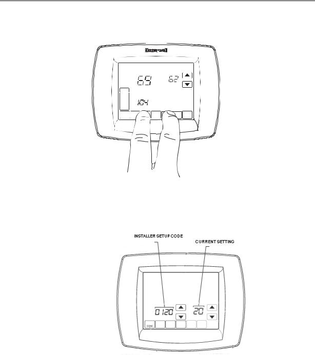
2.Press and hold the two blank keys on either side of the center key for approximately five seconds (see Figure 10).
MO |
TU |
WE |
TH |
FR |
SA |
SU |
|
Inside |
|
|
Set To |
|
|
SYSTE |
|
|
|
Following |
|
|
|
|
|
Schedule |
|
||
|
|
|
|
|
||
M |
|
|
|
|
|
|
EM |
|
|
|
|
|
|
HEAT |
|
|
|
|
|
|
OFF |
|
|
|
|
|
|
DON |
|
|
|
|
|
CANC |
M19923
Figure 10 Entering ISU mode
The installer setup (ISU) screen appears. An ISU code is displayed in the lower left. It is a four-digit code beginning with zero. The current setting is displayed in the lower right.
Figure 11 ISU screen
3.Use the down arrow next to the installer setup code to advance to ISU code 800.
4.Use the up and down arrows next to the current setting to set ISU code 800 (MAC address) to a value between 0 and 127.
5.Set ISU code 801 (first digit of device instance) to a value between 0 and 4.
Note The device instance is set by entering values in four separate ISU codes. See example on page 20.
© Honeywell |
31-00098-01 |
19 |

Installation and Operations Guide | BACnet FF
6.Set ISU code 802 (second and third digits of device instance) to a value between 00 and 99.
7.Set ISU code 803 (fourth and fifth digits of device instance) to a value between 00 and 99.
8.Set ISU code 804 (sixth and seventh digits of device instance) to a value between 0 and 99.
9.Press Done to exit installer setup.
For example, if you want to set the MAC address to 15 and the device instance to 1876, you would use these settings:
ISU code 800=15 ISU code 801=0 ISU code 802=00 ISU code 803=18 ISU code 804=76
Installer setup (ISU) codes
Installer setup mode provides access to functions specific to installation of a BACnet FF. Some BACnet FF configuration parameters can be altered from the ISU screens. The ISU parameters can also be accessed via BACnet.
You can require a PIN to access ISU mode by setting AV-133 to a non-zero, four-digit number.
To access the ISU screens
1.From the home screen, press SYSTEM (left side of the screen).
2.Five blank touch keys appear on the bottom of the screen between the Done and Cancel keys. Press and hold the two blank keys on either side of the center key for approximately five seconds. See Figure 10.
3.If a PIN code is required, use the top arrows to select the first two digits of the code and the bottom arrows to select the third and fourth digits of the code, and then press DONE.
The ISU screen appears.
4.Use the arrows to select parameters and values. See Table 3 for details.
5.Press DONE.
20 |
31-00098-01 |
© Honeywell |
Installation and Operations Guide | Configuration
Note After five minutes of inactivity, the ISU screen reverts to the main screen.
Table 3 provides a list of ISU parameters
Table 3 |
ISU parameters |
|
|
||
|
|
|
|
|
|
|
ISU |
|
|
|
|
|
Parameter |
Description |
Allowed Values |
||
|
Code |
|
|
|
|
|
120 |
|
Year, first 2 digits |
19-21 |
|
|
|
|
|
|
|
|
130 |
|
Year, second 2 |
00-99 (00-54 if ISU 200=21) |
|
|
|
|
digits |
|
|
|
|
|
|
|
|
|
140 |
|
Month |
1-12 |
|
|
|
|
|
|
|
|
150 |
|
Day |
1-31 |
|
|
|
|
|
|
|
|
160 |
|
Schedule format |
0 – not programmable (BV-133=0) 4 – 7 |
|
|
|
|
BV-133 |
day programmable (BV-133=1) |
|
|
|
|
|
|
|
|
280 |
|
Backlight control |
0 |
– on for 20 seconds after keypress |
|
|
|
BV-79 |
1 |
– low always on, bright after keypress |
|
|
|
|
|
|
|
320 |
|
Swap |
1 |
– show opposite units to specified in |
|
|
|
English/Metric |
DDC header |
|
|
|
|
BV-69 |
|
|
|
|
|
|
|
|
|
330 |
|
Daylight saving |
0 |
– off; no automatic adjustments |
|
|
|
AV-127 |
1 |
– pre 2007 scheme |
|
|
|
2 |
– 2007 and later scheme |
|
|
|
|
|
||
|
|
|
|
|
|
|
500 |
|
Filter change |
0 |
– reminder not used |
|
|
|
reminder |
1 |
– 10 days |
|
|
|
AV-124 |
2 |
– 30 days |
|
|
|
3 |
– 60 days |
|
|
|
|
|
||
|
|
|
|
4 |
– 90 days |
|
|
|
|
5 |
– 120 days |
|
|
|
|
6 |
– 365 days |
|
|
|
|
|
|
|
510 |
|
Hum pad change |
0 |
– reminder not used |
|
|
|
reminder |
1 |
– 90 days |
|
|
|
AV-125 |
2 |
– 180 days |
|
|
|
3 |
– 365 days |
|
|
|
|
|
||
|
|
|
|
|
|
|
520 |
|
UV lamp change |
0 |
– reminder not used |
|
|
|
reminder |
1 |
– 365 days |
|
|
|
AV-126 |
|
|
|
|
|
|
|
|
|
540 |
|
Program periods |
2 |
– Wake/Sleep |
|
|
|
AV-129 |
4 |
– Wake/Leave/Return/Sleep |
|
|
|
|
|
|
|
|
|
|
|
|
|
640 |
|
Clock format |
12 – 12 hour (BV-83=0) |
|
|
|
|
BV-83 |
24 – 24 hour (BV-83=1) |
|
|
|
|
|
|
|
|
|
|
|
|
|
|
670 |
|
Keypad lock |
0 |
– no lock |
|
|
|
AV-128 |
1 |
– access temperature settings only |
|
|
|
2 |
– fully locked |
|
|
|
|
|
||
|
|
|
|
|
|
|
|
|
|
|
|
© Honeywell |
31-00098-01 |
|
21 |
||

Installation and Operations Guide | BACnet FF
Table 3 |
ISU parameters |
|
||
|
|
|
|
|
|
ISU |
|
|
|
|
Parameter |
Description |
Allowed Values |
|
|
Code |
|
|
|
|
700 |
|
Sensed room |
-4 to +4 degrees F |
|
|
|
temperature offset |
|
|
|
|
(AV-138) |
|
|
|
|
|
|
|
701 |
|
Sensed room |
-5% TO +5% |
|
|
|
humidity offset |
Humidity cannot be adjusted above |
|
|
|
(AV-139) |
100% or below 0%. |
|
|
|
|
|
|
702 |
|
Sensed outside air |
-4 to +4 degrees F |
|
|
|
temperature offset |
|
|
|
|
(AV-140) |
|
|
|
|
|
|
|
703 |
|
Sensed outside |
-5% TO +5% |
|
|
|
humidity offset |
Humidity cannot be adjusted above |
|
|
|
(AV-141) |
100% or below 0%. |
|
|
|
|
|
|
800 |
|
MS/TP MAC |
0-127 |
|
|
|
|
|
|
801 |
|
BACnet Device |
0-4 |
|
|
|
Instance - first digit |
|
|
|
|
|
|
|
802 |
|
BACnet Device |
00-99 |
|
|
|
Instance second and |
|
|
|
|
third digits |
|
|
|
|
|
|
|
803 |
|
BACnet Device |
00-99 |
|
|
|
Instance forth and |
|
|
|
|
fifth digits |
|
|
|
|
|
|
|
804 |
|
BACnet Device |
00-99 |
|
|
|
Instance sixth and |
|
|
|
|
seventh digits |
|
|
|
|
|
|
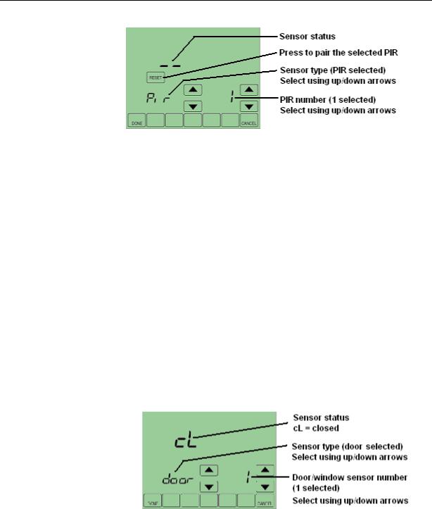
Pairing a sensor to a wireless BACnet FF
The BACnet FF and wireless sensor kits (WSK-24) ship unpaired, verified by two dashes in the Sensor Status field on the BACnet FF’s Wireless Sensor Setup screen. To pair them, issue a pairing command from the BACnet FF and then activate the sensor.
Accessed from Field Service Mode, the BACnet FF’s Wireless Sensor Setup Mode includes diagnostic screens for configuration and checkout of associated sensors. With :UC displayed in Field Service Mode, press the blank key (blank area) just to the left of the blank center key, and then press the down arrow key next to the :UC parameter.
Door/window sensors may be paired to any available sensor number in the range 1-8. When cycling through sensor numbers on the Wireless Sensor Setup screen, unpaired sensor numbers show a status of --.
PIR sensors may be paired to any available sensor number in the range 1-3.
22 |
31-00098-01 |
© Honeywell |
Installation and Operations Guide | Configuration
Figure 12 Wireless Sensor Setup screen
To pair a sensor to a BACnet FF
1.Make sure the battery is installed and activated in the sensor.
2.If the sensor is a door/window switch, align the magnet so that the sensor is in the closed position. If the sensor is a PIR sensor, cover the PIR.
IMPORTANT! Verify that the sliding door/window contact is closed and cover all other PIRs to prevent interference during the pairing process.
3.On the BACnet FF select the sensor to pair and then press Reset. The RESET key disappears and WAIT is displayed indicating that the BACnet FF is waiting to pair the sensor with the next device that receives a radio signal.
4.Activate the sensor you want to pair.
Note Pairing times out after 10 seconds of no pairing activity.
5.Verify that the BACnet FF and sensor successfully paired. Paired = sensor status is displayed, replacing --.
Timed out = RESET is displayed and sensor status is --.
Figure 13 Door sensor number 1 paired and in closed status.
To erase sensor-to-BACnet FF pairings
1.While viewing any sensor status screen while pairing is not taking place, press the blank key to the left of CANCEL.
2.Press the blank key to the right of DONE.
The sensor status field displays --, indicating unpaired.
© Honeywell |
31-00098-01 |
23 |

Installation and Operations Guide | BACnet FF
Fixed field service codes
Field service mode enables technicians to query and command key operating variables in the BACnet FF while at the BACnet FF touchscreen. A technician presses a particular key sequence at the BACnet FF to enter field service mode. In field service mode a technician uses the left arrows to scroll through data codes and the right arrows to change the value associated with a code.
The lower left of the LCD shows the two-digit data code and the main area displays the data value. A pre-defined list of data codes is available within the description of each application. See Table 8 as an example for applications 0 and 1. “Configuring a DDCMULTI application” on page 27 provides more information about these settings.
Note When using the local user interface to change applications (AV-49), the application defaults will NOT change and must be changed manually.
You can deny users access to field service mode by setting BV-68 to ON. You can also require a PIN code in order to enter field service mode by setting AV-132 to the desired PIN number.
Field service mode ends automatically if there is no key activity for five minutes.
Setting field service codes
To set field service codes
1.From the home screen, press SYSTEM (left side of the screen).
2.Press and hold the center bottom key (blank) for about five seconds. See Figure 10.
3.If a PIN code is required, use the top arrows to select the first two digits of the code and the bottom arrows to select the third and fourth digits of the code, and then press DONE.
The field service screen appears.
4.Press the left up or down arrows until the desired code appears. See Table 8 on page 42 for the list of Setup Codes. NOTE: All applications use the same Setup Codes.
5.Press the right up or down arrows to adjust the value associated with the code.
6.Press the left up or down arrows to accept the change and scroll to a different code.
7.Press DONE to exit field service mode.
24 |
31-00098-01 |
© Honeywell |

Installation and Operations Guide | Operational overview
Operational overview
The BACnet FF operates in one of three modes - Setpoint, Occupancy Single Setpoint, and Occupancy Dual Setpoint.
Common features
This section describes features common to all operating modes. For descriptions of mode-specific features, see “Checking MS/TP communication” on page 26 and “Checking MS/TP communication” on page 26.
LCD backlight operation
BV-79 controls backlight operation. If BV-79 is OFF, the backlight turns ON when any key is pressed and stays on for 20 seconds after there is no key activity. If BV-79 is ON, the backlight is ON continuously.
Clock operation
The BACnet FF’s real-time clock provides time and date for displaying the date and time, implementing daylight savings settings, and implementing schedules. If AC power is lost, a supercapacitor will power the clock for ten days. If the date and time are lost, the BACnet FF will display the set time and date screens when powered up.
Note The real-time clock is separate from the CPU time keeping utility. It only affects the items listed in this section.
Daylight savings (DLS) settings can be controlled by a BACnet FF or by a
BACnet Supervisor. If installer setup (ISU) parameter 330 is set to non-zero, the
BACnet FF will control DLS settings. If ISU 330 is zero, DLS is controlled by a
BACnet Supervisor.
The clock accepts time syncs from a BACnet Supervisor. If configured in DDC, the date and time can also be set manually using the display. To deny a user permission to set the clock, set BV-116 to 1.
The last time command, whether from the user screen or BACnet, takes precedence.
To adjust the real-time clock
1.Press CLOCK.
2.Use the arrow keys to select a year, month, and day.
3.Press DONE.
4.Select a time.
5.Press DONE.
© Honeywell |
31-00098-01 |
25 |

Installation and Operations Guide | BACnet FF
MORE key navigation
The MORE key allows a programmer to make additional screens available to users. Enabling the display of one or more of these screens causes the MORE key to appear on the main screen. The screens that can be made available are:
•Outside air temperature
•Inside/outside humidity
When the user presses MORE, the first enabled screen appears. Pressing
MORE again displays the next screen.
Touchscreen cleaning
If the display screen needs to be cleaned, the user presses SCREEN. The display will lock for 30 seconds allowing the user to wipe the screen without pressing any keys. When the display reads 0, press SCREEN to continue cleaning or DONE to quit. Use a non-abrasive glass cleaner.
Checking MS/TP communication
You can check MS/TP communication from the display. The BACnet FF will indicate if MS/TP packets and headers have been seen, the baud rate, and the MAC address.
To check MS/TP communication
1.Enter field service mode. See “To set field service codes” on page 24.
2.Ensure the UC code is displayed.
3.Press the blank key usually labeled MORE (bottom row, second from right).
4.Press the down arrow near the UC code. The MS/TP communication screen appears.
Baud rate |
|
|
|
|
Headers seen |
|
|
|
|
|
|||
|
|
|
|
|
|
Requests seen |
|
|
|
|
|
|
MAC address |
|
|
|
|
|
|
|
5. Press DONE twice to exit.
26 |
31-00098-01 |
© Honeywell |

Installation and Operations Guide | Configuring a DDCMULTI application
Configuring a DDCMULTI application
The BACnet FF is pre-loaded with DDC that lets you select one of multiple applications. Applications for heat pumps, A/C units, and fan coil units are all contained in the same DDC file. Using one of these applications, an installer can configure the controller in the field - just set the MS/TP parameters, device instance, and application [AP] (AV-49) parameters and it is ready to go.
Note When using the local user interface to change applications (AV-49), the application defaults will NOT change and must be changed manually. However, The Niagara-based configuration wizard will change the application specific default values.
Advanced application settings will require a BACnet connection to a BACnet BMS. These detailed application settings need to be reviewed to ensure all are set correctly before enabling the device's outputs.
CAUTION Setting the [OE] field service code to ON powers up the outputs. Ensure that the outputs are configured correctly before setting OE to ON.Failure to do so may result in equipment damage.
1.Set field service code [OE] (BV-2) to ON to power up the outputs.
2.Press DONE.
© Honeywell |
31-00098-01 |
27 |

Installation and Operations Guide | BACnet FF
Application Sequences and Configuration Settings
Table 4 shows settings for all 19 applications and should be referenced accordingly
Table 4 |
Primary settings for the 19 apps |
|
|
|
|
|
||
|
|
|
|
|
|
|
|
|
Code |
Point |
Value |
Default |
|
Options |
Units |
Notes |
|
160 |
BV-133 |
Internal Sched |
Inactive |
|
Inactive/Active |
|
|
|
|
|
Enable |
|
|
|
|
|
|
|
|
|
|
|
|
|
|
|
280 |
BV-79 |
Backlight ON |
Inactive |
|
|
|
|
|
|
|
|
|
|
|
|
|
|
320 |
BV-69 |
Swap Eng - |
|
|
|
|
|
|
|
|
Don't use this is |
|
|
|
|
|
|
|
|
on custom |
|
|
|
|
|
|
|
|
screen |
|
|
|
|
|
|
|
|
|
|
|
|
|
|
|
330 |
AV-127 |
Day Light |
2 |
|
0-2 |
|
0 - disable, 1 - pre 2007, 2 - |
|
|
|
Savings Option |
|
|
|
|
2007+ |
|
|
|
|
|
|
|
|
|
|
500 |
AV-124 |
Filter Period |
0 |
|
0 |
|
|
|
|
|
|
|
|
|
|
|
|
510 |
AV-125 |
Pad Period |
0 |
|
0 |
|
|
|
|
|
|
|
|
|
|
|
|
520 |
AV-126 |
UV Period |
0 |
|
0 |
|
|
|
|
|
|
|
|
|
|
|
|
540 |
AV-129 |
Prog Periods |
0 |
|
0 |
|
|
|
|
|
|
|
|
|
|
|
|
640 |
BV-83 |
Clock Fmt |
|
|
|
|
|
|
|
|
Inactive 12 hr |
|
|
|
|
|
|
|
|
Active 24 hr |
|
|
|
|
|
|
|
|
|
|
|
|
|
|
|
670 |
AV-128 |
Keypad Lock |
|
|
|
|
|
|
|
|
0-no lock, |
|
|
|
|
|
|
|
|
1-temp settings |
|
|
|
|
|
|
|
|
only, 2-locked |
|
|
|
|
|
|
|
|
|
|
|
|
|
|
|
700 |
AV-138 |
Temp Offset |
0 |
|
0 |
|
|
|
|
|
|
|
|
|
|
|
|
701 |
AV-139 |
Humidity Offset |
0 |
|
0 |
|
|
|
|
|
|
|
|
|
|
|
|
702 |
AV-140 |
OA Temp Offset |
0 |
|
0 |
|
|
|
|
|
|
|
|
|
|
|
|
703 |
AV-141 |
Humidity Offset |
0 |
|
0 |
|
|
|
|
|
|
|
|
|
|
|
|
|
BV-141 |
Deny Schedule |
Inactive |
|
Inactive/Active |
|
|
|
|
|
Edits |
|
|
|
|
|
|
|
|
|
|
|
|
|
|
|
|
BV-114 |
Deny Schedule |
Inactive |
|
Inactive/Active |
|
|
|
|
|
View |
|
|
|
|
|
|
|
|
|
|
|
|
|
|
|
|
BV-115 |
Deny |
Inactive |
|
Inactive/Active |
|
|
|
|
|
Permanent Hold |
|
|
|
|
|
|
|
|
|
|
|
|
|
|
|
|
BV-130 |
Deny Vacation |
Inactive |
|
Inactive/Active |
|
|
|
|
|
Hold |
|
|
|
|
|
|
|
|
|
|
|
|
|
|
|
|
BV-116 |
Deny Clock |
Inactive |
|
Inactive/Active |
|
|
|
|
|
Adjust |
|
|
|
|
|
|
|
|
|
|
|
|
|
|
|
|
AV-132 |
FS PIN |
0 |
|
0 |
|
Pin locks field service |
|
|
|
|
|
|
|
|
access |
|
|
|
|
|
|
|
|
|
|
|
AV-133 |
ISU PIN |
0 |
|
0 |
|
Pin locks ISU service access |
|
|
|
|
|
|
|
|
|
|
|
|
|
|
|
|
|
|
|
28 |
|
|
|
31-00098-01 |
|
© Honeywell |
||

Installation and Operations Guide | Heat Pumps: Apps 0 and 1 [AP] 0: Air-to-air heat pump and [AP] 1:
Heat Pumps: Apps 0 and 1
[AP] 0: Air-to-air heat pump and [AP] 1: Water-source heat pump
Single-speed fan with binary output start/stop. optional analog variable-speed fan control, 1-stage auxiliary heat, optional floating or analog economizer.
Fan mode control (AV-17)
•1 = continuous
•2 = cycle with heating
•3 = cycle with heating/cooling
Configurable Occupancy Modes
•SYSTEM Block: AUTO/OFF selection (Occupied/Unoccupied)
•Occupancy mode (AV-123=0, default): Schedules Occupancy states
•Setpoint mode (AV-123=1): Schedules Setpoints
•Dual setpoint mode (AV-123=2): Dual setpoints when Occupied
•Internal schedules enabled when BV-133 is active or ISU 160=4
•BMS schedules enabled when BV-56 is active
Inputs and Outputs
Table 5 |
Inputs and Outputs: [AP] 0 and [AP] 1 |
||
|
|
|
|
|
Point |
|
Function |
|
AI-0 |
|
Optional: |
|
|
|
Use as space sensor in place of the internal space |
|
|
|
sensor AV-104 (Set BV-32 active and BV-47 inactive) |
|
|
|
Use as an outdoor-air sensor; maps to display |
|
|
|
AV-103 (Set BV-47 active and BV-32 inactive) |
|
|
|
|
|
BI-1 |
|
Optional standby input (for PIR/door/window sensor) |
|
|
|
|
|
AI-2 |
|
Supply-air sensor (optional, but required for |
|
|
|
economizer option) |
|
|
|
|
|
BI-2 |
|
Normally-open condensate sensor (optional) |
|
|
|
|
|
BO-0 |
|
Fan |
|
|
|
|
|
BO-1 |
|
Heat-pump compressor |
|
|
|
|
|
BO-2 |
|
Reversing valve |
|
|
|
|
|
BO-3 |
|
Heating stage 1 (optional) |
|
|
|
|
© Honeywell |
31-00098-01 |
29 |
Installation and Operations Guide | BACnet FF
Table 5 |
Inputs and Outputs: [AP] 0 and [AP] 1 |
||
|
|
|
|
|
Point |
|
Function |
|
BO-4 |
|
Economizer open (optional) |
|
|
|
|
|
BO-5 |
|
Economizer close (optional) |
|
|
|
|
|
AO-0 |
|
Economizer (optional) |
|
|
|
|
|
AO-1 |
|
Analog fan speed (optional) |
|
|
|
|
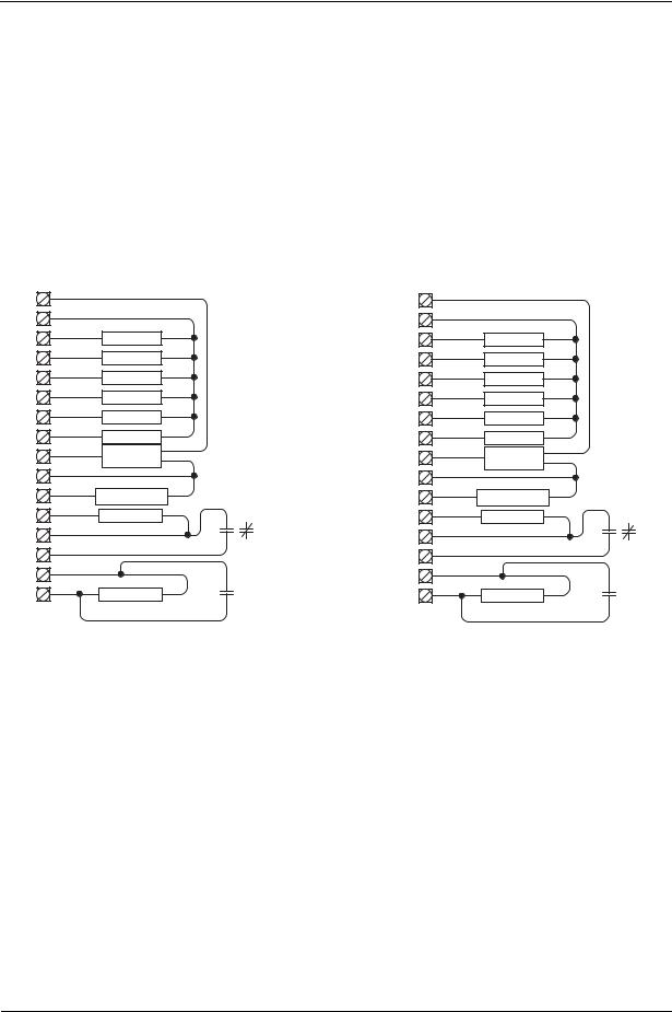
Wiring diagrams
|
Controller Terminations |
|||
1 |
HPH1 AP 0 |
|
||
24VAC |
RC |
|
|
|
5 |
|
|
|
|
GND |
C |
|
|
|
BO 0 |
G |
Fan |
|
|
|
|
|
||
BO 1 |
Y1 |
HP Cmpr |
||
|
|
|
||
BO 2 |
O/B |
Rev Vlv |
|
|
|
|
|
||
BO 3 |
W1 |
Htg Stg 1 |
||
|
|
|
||
BO 4 |
EC |
Econ Opn |
||
|
|
|
||
BO 5 |
EC |
Econ Cls |
|
|
|
|
|
||
|
0-10Vdc |
|
24V |
|
AO 0 |
EC 4-20ma |
Econ Com |
||
Com |
|
|
|
|
14 |
VC |
|
Optional |
|
AO 1 |
VFD /SCR |
|||
4-20ma |
Standby |
|||
|
|
N.C. or N.O. |
||
BI/AI 0 |
|
Sensor * |
||
|
|
|||
COM |
|
|
|
|
BI/AI 1 |
|
|
|
|
COM |
|
|
Optional |
|
|
|
SA Sensor |
||
BI/AI 2 |
|
Condensate |
||
alarm or fail
* Optional space or outside temperature sensor.
|
Controller Terminations |
|||
1 |
HPH1 AP 1 |
|
||
|
|
|
||
24VAC |
RC |
|
|
|
5 |
|
|
|
|
GND |
C |
|
|
|
BO 0 |
G |
Fan |
|
|
|
|
|
||
BO 1 |
Y1 |
HP Cmpr |
||
|
|
|
||
BO 2 |
O/B |
Rev Vlv |
|
|
|
|
|
||
BO 3 |
W1 |
Htg Stg 1 |
||
|
|
|
||
BO 4 |
EC |
Econ Opn |
||
|
|
|
||
BO 5 |
EC |
Econ Cls |
|
|
|
|
|
||
|
0-10Vdc |
|
24V |
|
AO 0 |
EC 4-20ma |
Econ Com |
||
Com |
|
|
|
|
14 |
VC |
|
Optional |
|
AO 1 |
VFD /SCR |
|||
4-20ma |
Standby |
|||
|
|
N.C. or N.O. |
||
BI/AI 0 |
|
Sensor * |
||
|
|
|||
COM |
|
|
|
|
BI/AI 1 |
|
|
|
|
COM |
|
|
Optional |
|
|
|
SA Sensor |
||
BI/AI 2 |
|
Condensate |
||
alarm or fail
* Optional space or outside temperature sensor.
Figure 14 Controller terminations: [AP] 0, [AP] 1
Sequences of Operation
Controller outputs are disabled when Enable Outputs [OE] BV-2 OF/On is in the OF (inactive) state. Do not enable outputs until you are certain the wiring and configuration is correct and complete.
SYSTEM Block Control (BV-102)
When the unit is configured to run in Occupancy Mode, the SYSTEM Block allows the user direct control of occupied or unoccupied state from the controller display. Selecting “Auto” places the controller in Occupied state. Selecting “OFF” places the controller in unoccupied state.
The SYSTEM Block can be hidden by setting BV-102 inactive. When the SYSTEM Block is hidden occupancy states are controlled exclusively by the onboard or BMS schedules.
30 |
31-00098-01 |
© Honeywell |
Loading...