


HONEYWELL
TE657W
Black-Masked Weather Forecaster with Heat Index
(TE657W)
USER MANUAL
Version Date 2-22-08
TABLE OF CONTENTS |
|
INTRODUCTION |
3 |
STANDARD PACKAGE CONTENTS |
3 |
INSTALLATION |
4 |
BEFORE YOU BEGIN |
5 |
REMOTE TEMPERATURE & HUMIDITY SENSOR |
|
MAIN UNIT |
8 |
NAVIGATING THROUGH THE MODES |
14 |
CUSTOMiZING YOUR WEATHER FORECASTER |
16 |
BACKLIGHT |
|
USING DIFFERENT DISPLAY WINDOWS |
17 |
PRESSURE WINDOW |
17 |
CLOCK WINDOW |
21 |
SUNRISE/SUNSET/MOONPHASE WINDOW |
26 |
TEMPERATURE HUMIDITY & HEAT INDEX WINDOW |
|
MAINTANANCE (MAINTENANCE) |
34 |
TROUBLESHOOTING |
35 |
PRECAUTIONS |
36 |
APPENDIX – CITY CODES |
36 |
SPECIFICATIONS |
39 |
FCC STATEMENT |
40 |
DECLARATION OF CONFORMITY |
41 |
STANDARD WARRANTY INFORMATION |
41 |
2
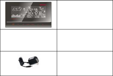
INTRODUCTION
Thank you for selecting the Honeywell Black-Masked Weather Forecaster with Heat Index. This device combines precise time keeping, monitoring and its graphical display of heat index, temperature and humidity data from up to three remote locations. Keep this manual handy as it contains practical instructions, technical specifications and precautions. Included you will find:
•One User Manual
•One Quick Start Guide
Main Unit TE657W (receiver)
three-channel remote thermo-hygrometer TS33C
AC adapter
INSTALLATION
The Honeywell Black-Masked Weather Forecaster with Heat Index TE657W communications between the main unit (receiver) and the remote sensor (transmitter) are wireless, thus simplifying the installation. The remote temperature and humidity sensor transmits data to the main unit, with an
operating range of up to 200 feet (60 meters) in the open.
The remote temperature and humidity sensor can be placed indoors or outdoors, depending on the area where the temperature and humidity are intended to be measured. If you intend measuring outdoor temperature and humidity, place the remote sensor outdoors.
NOTE: It is critical to power the remote sensor BEFORE setting up the main unit.
NOTE: It is critical to power up and test communication between the remote sensor and the main unit BEFORE permanently mounting it outside.
3 |
3 |
4 |
BEFORE YOU BEGIN
•We recommend using alkaline batteries for the remote sensor and the main unit. When outdoor temperatures are below 32°F (0°C) we recommend using lithium batteries.
•Avoid using rechargeable batteries. (Rechargeable batteries cannot maintain correct power requirements)
•ALWAYS install batteries in the remote sensor before the main unit
•Insert batteries before first use, matching the polarity in the battery compartment
•Remove protective plastic screen from LCD display (if any)
•During initial set up, place the remote sensor close to the main unit
•After reception is established (remote readings will appear on the main unit’s display), position the remote sensor and the main unit within the effective transmission range of up to 200 feet (60 meters). Ideally the remote sensor should be placed within the line of sight from the main unit.
•Transmission/reception range may be affected by trees, metal structures, electronic appliances, surrounding building materials, main unit location and transmitter (remote sensor) positioned.
•The main unit must be placed indoors.
•Place the remote sensor so that it faces the main unit (receiver), minimizing obstructions such as doors, walls and furniture.
NOTE: Battery voltage levels in the outdoor sensor may drop with below freezing temperatures, this may reduce the transmission range. For optimum performance, at temperatures below 32°F (0°C) We recommend lithium batteries.
5
REMOTE TEMPERATURE & HUMIDITY SENSOR
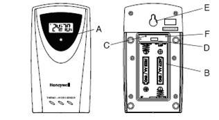
FEATURES
•Remote data transmission to the main unit via 433 MHz frequency
•LCD displays temperature, humidity and channel
•Selection of the temperature display in Celsius or Fahrenheit
•Three transmission channels
•Case can be wall mounted using built-in hanger
A.LED INDICATOR
•Flashes once about every 45 seconds with each transmission to the main unit.
•Flashes twice when battery power is low.
B.BATTERY COMPARTMENT
•Holds two AA-size batteries
C.RESET
•Resets all previous settings
D.CHANNEL SWITCH
•Selects the desired channel: 1, 2 or 3
E.WALL-MOUNT RECESSED OPENING
•Mounts the remote sensor on the wall
F.°C/°F SWITCH
5 |
6 |
•Selects the temperature display in Fahrenheit or Celsius
NOTE: Install the batteries; select the channel and temperature in °C or °F before mounting the sensor.
BATTERY INSTALLATION
•Remove the screws from the battery compartment with a small Phillips screwdriver
•Set the channel 1 through 3. The switch is located in the battery compartment. Channel 1 is typically selected if only one remote sensor is being used
•Install 2 “AA” size alkaline batteries (not included) matching the polarities shown in the battery compartment
•Select the temperature unit by pressing °C/°F switch with a paper clip or similar tool
•Replace the battery compartment door and secure the screws
•Secure the remote sensor in the desired location
MOUNTING
•The remote thermo-hygrometer sensor can be placed on the flat surface or mounted on the wall in vertical position
•Use a screw, rather than a nail, for best mounting of the sensor
•When mounting the main unit on the wall or vertical surface, fold the table stand back into the unit.
PLACEMENT
•The remote thermo-hygrometer sensor should be placed under eaves or a similar location with free air circulation yet sheltered from direct sunlight and extreme weather
•Ideally, place the thermo-hygrometer sensor over soil, rather than asphalt which would cause false readings.
7
•Avoid placing the thermo-hygrometer sensor near sources of heat, such as chimneys and heating elements
•Avoid areas that collect heat from the sun and radiate heat, such as metal, brick or concrete structures, paving, and patios
•The international standard for the valid air temperature measurements is 4 feet (1.25meters) above the ground
OPERATION
Immediately after batteries are correctly installed, the remote sensor will start transmitting a temperature and humidity data to the main unit.
MAIN UNIT
The main unit measures pressure, indoor temperature, humidity, calculates heat index. It also receives atomic time data from the US WWVB Atomic Clock and readings from up to three remote sensors. It should be placed indoors.
FEATURES
Time
•Precise time and date set via signals from the US Atomic clock
•12 or 24 hour time format
•Manual adjustment of time and date
•Calendar date with month and day in 6 languages English, German, French, Italian, Spanish and Dutch
•Sunrise/set calculation for over 100 pre-programmed cities based on geographical information entered by the user
•Moon Phase calendar and historical data for days
•Dual crescendo alarms with snooze
•Programmable Ice Warning Alarm
7 |
8 |
Weather
•Weather forecast for the next 12 to 24 hour in seven large icons: Sunny, Slightly Cloudy, Cloudy, Light Rainy, Heavy Rainy, Light Snowy, Heavy Snowy and Stormy
•Barometric pressure in imperial or metric units
•Altitude adjustment for pressure compensation
•24 hour barometric pressure history chart
•User-defined High/Low Temperature alarm
•Indoor/Outdoor Temperature & Humidity in up to 3 remote locations (additional sensors required)
•Comfort level indicators (Dry, Humid, etc)
•Heat Index and level measurements
•Operating range of up to 200 feet (60 meters)
Power
•4 AA batteries (main unit)
•2 AA batteries (remote sensor)
BATTERY INSTALLATION
•Remove the battery compartment door located on the back of the main unit.
•Insert four (4) AA size batteries according to the polarities shown and replace the battery compartment door.
•When placing the main unit on the table or other horizontal surface, unfold the table stand for the desired viewing angle.
PLACEMENT
•Make sure that the main unit is locating within the operating range of all remote weather sensors.
9
•Ideally the remote weather sensors should be mounted within the line of sight of the main unit.
•Transmission range may be affected by trees, metal structures and electronic appliances.
•Test reception before permanently mounting all the remote weather sensors.
Avoid placing the main unit in the following areas:
•Direct sunlight and surfaces emitting and radiating heat, such as heating ducts or air conditioners.
•Areas with interference from wireless devices (cordless phones, radio headsets, baby monitoring devices and other electronics.)
OPERATION
Once the main unit is powered, the display will show all available LCD segments for a moment.
IMPORTANT: All of the display functions will be locked, allowing setting your local altitude and pressure parameters by pressing the UP (+) or DOWN (--) and SET buttons. The locked display will show the pressure icon and abbreviation “inHg” flashing in the Pressure Window, default time in Clock Window, default sunset/sunrise time in the Sunrise/Sunset Window and channel 1’s temperature and humidity readings in Temperature/Humidity Window.
If pressure and altitude are not configured during this time, the unit will self-calibrate in a few minutes and show the default settings for the pressure and altitude (sea level) and all remote weather sensors readings.
9 |
10 |

FRONT
A B C D
E F G H I J K
11
REAR
L
M
N
P
TOP
O
A.WEATHER AND PRESSURE WINDOW
B.TEMPERATURE & HUMIDITY WINDOW
C.CLOCK WINDOW
D.SUNRISE/ SUNSET WINDOW
E.ALARM/ CHART button
•Displays available alarms – for time and temperature
•Press and hold, to enter the alarm programming mode for a desired parameter
11 |
12 |

•In barometric pressure/forecast mode. Press and hold to view temperature and humidity history charts
F.SET button
•Toggles between operating modes within each window
•Press & hold, to activate programming mode and enter changes to the selected parameter
•Press, to exit programming mode and confirm programmed settings
G.MEMory button
•Press, to display stored measurements. Toggles between: current, minimum, maximum readings of the indoor and remote temperature & humidity
•Clears the MEMory
•Activates a searching mode of sunrise/sunset and moon phase records
H.HISTORY button
•Press, to display the SEA LEVEL pressure history records. Steps backwards in time with -1 hour increments
I.CHANNEL button
•Recalls a different remote sensor reading – 1,2, or 3
•An automatic scan of 3 remote channels will initiate when you press and hold the channel button
J.DOWN (--) button
•Press, to select next available mode anti-clockwise
•Decreases the parameters
•Press & hold, to search for signals from the remote sensors
•Enables or disables time alarms: (W) weekday, (S) single and ice warning alarm
K.UP (+) button
•Press, to select next available mode clockwise
13
•Increases the parameters
•Press & hold, to search for atomic time signal
•Enables or disables time alarms (W) weekday and (S) single and ice warning alarm
L.WALLMOUNT
•A recessed opening to mount the unit on a wall
M.BATTERY COMPARTMENT
•Accommodates (4) UM-3 or AA 1.5V alkaline batteries
N.POWER Input
O.SNOOZE button
•Temporarily disables alarms for 8 minutes
P.TABLE STANDS
NAVIGATING THROUGH THE MODES
The main unit has four (4) different modes (windows) including:
-Weather/Pressure
-In/Out Temperature & Humidity
-Time/Calendar
-Sunrise/ Sunset
Press UP (+) button on the front of the main unit to cycle through the modes clockwise or DOWN (--) counter-clockwise. When a specific mode is selected the corresponding window information will begin to flash.
 WEATHER/PRESSURE WINDOW
Displays:
•Weather forecast Icon
•Current pressure (local, sea level & altitude) and history bar-chart
13 |
14 |
 Loading...