


H46C
Table of contents
 Loading...
H46C,E Humidity Controllers
INSTALLATION INSTRUCTIONS
APPLICATION
The H46C,E Humidity Controllers are used with portable
and central unit dehumidifiers to maintain relative
humidity. The H46 has an spst, snap-acting switch
designed for line voltage circuits. The H46C has two
leadwires for switch box mounting. The H46E has an
electric cord with an interrupter plug.
INSTALLATION
When Installing this Product…
1. Read these instructions carefully. Failure to follow
them could damage the product or cause a hazardous condition.
2. Check the ratings given in the instructions and on
the product to make sure the product is suitable for
your application.
3. Installer must be a trained, experienced service
technician.
4. After installation is complete, check out product
operation as provided in these instructions.
CAUTION
Electrical Shock Hazard.
Can cause electrical shock or equipment
damage.
Disconnect power supply before connecting
wiring.
Location
Select a location about 5 ft (1.5 m) above the floor in an
area with good circulation at average temperature and
humidity for the area to be controlled. Avoid locations
near hot or cold air ducts and discharge air from the
controlled equipment.
Mounting H46C
1. Remove the setting knob.
2. Pull the cover forward from the device to remove.
3. Install a 2 in. x 3 in. (51 mm x 76 mm) vertical
switch box at the selected location.
4. Using the two screws provided, fasten the adapter
plate to the switch box as shown. See Fig. 1.
5. Pull the wires from the switch box through the
opening in the adapter plate and connect to the
H46 leadwires with the solderless connectors
(provided). See Fig. 4-6 for typical hookups.
6. Push the wires back into the switch box.
7. Place the H46 against the adapter plate, making
certain the tab at the bottom of the plate fits into the
notch on the H46.
8. Fasten the H46 to the adapter plate by tightening
the captive screw.
9. Replace the cover and the setting knob.
Mounting H46E
1. At the selected location, insert the two wood
screws (provided) into the wall 2 in. (51 mm)
vertically apart and protruding 1/16 in. (2 mm) from
the wall. See Fig. 2.
2. Position the H46 on the screws and slide it down
until the screws are in the slots.
3. Insert the dehumidifier plug into the end of the
interrupter plug. See Fig. 3.
4. Insert the interrupter plug into the electrical outlet.
NOTE: H46E has a 3-prong plug. When connecting to
the 2-prong receptacle, use the converter plug
(not included) and connect the pigtail lead to the
ground screw.
® U.S. Registered Trademark
Copyright © 2003 Honeywell International Inc. • • All Rights Reserved
69-1000B-1

H46C,E HUMIDITY CONTROLLERS
2 X 3 IN.
S
F
(COVER ON)
P
S
PROTECTION AS REQUIRED.
H46C,E
R
N
R
ADAPTER PLATE
H46
(COVER OFF)
NYLON
ELEMENT
SCREWS (2)
H46 CAPTIVE
MOUNTING SCREW
SWITCH BOX
ADAPTER PLATE
PLATE TAB
H46 LEADWIRES (2)
WALL SURFACE
Fig. 1. Mounting H46C on vertical switch box.
WOOD SCREW
2 IN.
KEYHOLES
IN BACK O
CASE (2)
WALL
SURFACE
H46
CORD
M7908
Fig. 2. Mounting H46E with two screws.
M7907
STANDARD WALL OUTLET
OR EXTENSION CORD
TO H46E
H46E PLUG
DEHUMIDIFIER PLUG
TO DEHUMIDIFIER
M7909
Fig. 3. Connecting H46E interrupter plug.
WIRING
Disconnect power supply before connecting wiring to
avoid electrical shock or equipment damage. All wiring
must comply with local codes and ordinances. Do not
exceed contact and coil ratings when wiring into the
system.
Connections and Operation
A dehumidistat in combination with the thermostat can be
used to run the air conditioner to control relative humidity
levels. The H46C dehumidistat and thermostat can be
wired in parallel or in series.
Wiring in parallel allows the dehumidistat to independently control the humidity level, but could cause
overcooling of the home. During unoccupied times, the
homeowner should set the thermostat to a relatively high
setting and control moisture using the dehumidistat.
Wiring in series prevents overcooling but the air
conditioner runs only when both the thermostat and
dehumidistat are calling. During unoccupied times, the
homeowner should set the thermostat to a relatively low
setting and control moisture using the dehumidistat.
HUMIDITY
CONTROLLER
RISE
L1
(HOT)
OWER
1
UPPLY
L2
PROVIDE DISCONNECT MEANS AND OVERLOAD
1
DEHUMIDIFIE
EXHAUST FA
OR AIR
CONDITIONE
M7915
69-1000B-1 2
Fig. 4. Typical wiring diagram for H46C,E.
H46C,E HUMIDITY CONTROLLERS
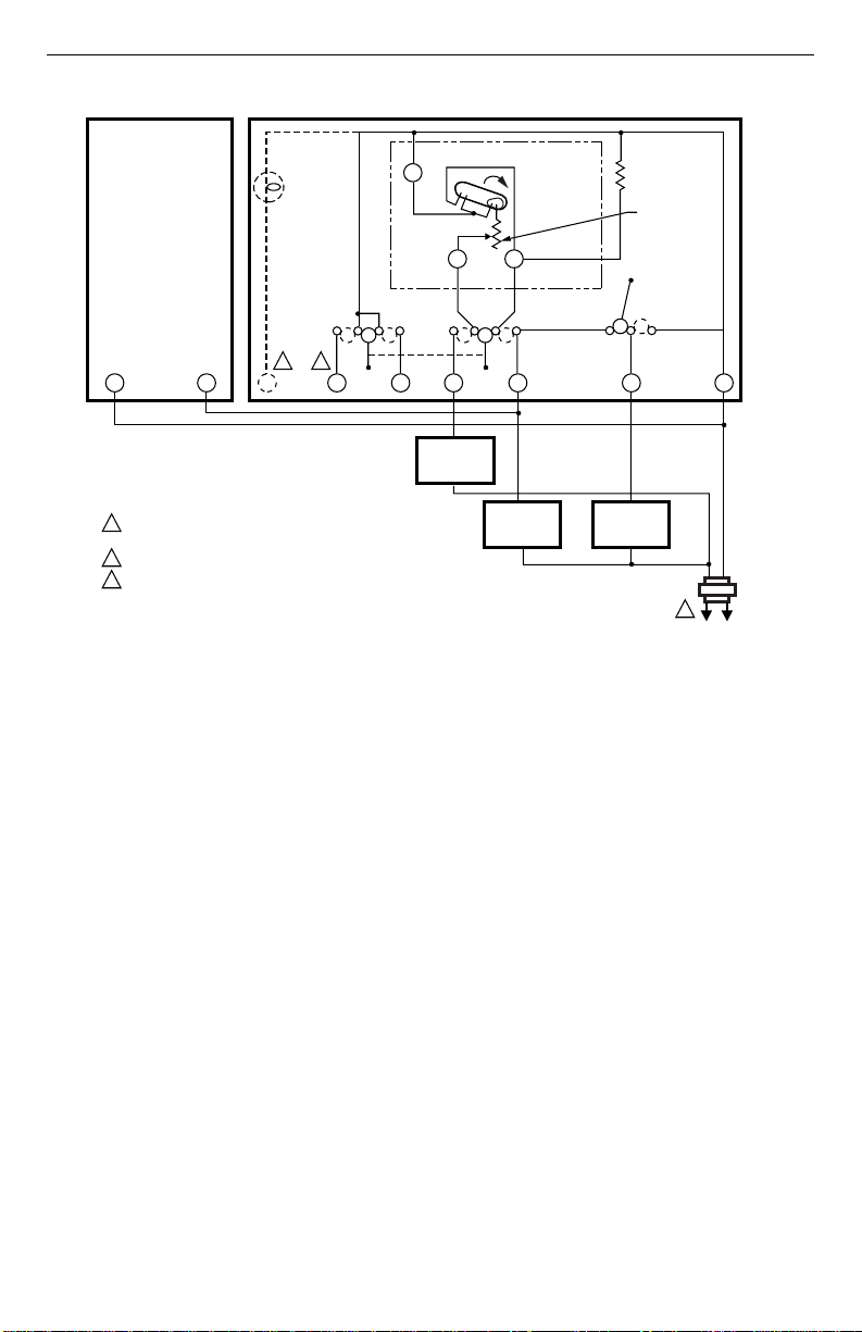
3
H46C
FILTER
LIGHT
HEAT OFF FANAUTO ONCOOL
3 2
1
PROVIDE OVERLOAD PROTECTION AND DISCONNECT MEANS
AS REQUIRED.
HEATING DAMPER MOTOR, IF USED.
2
3
CLOGGED FILTER SWITCH OR COOLING PANEL CONNECTION.
Fig. 5. Typical parallel wiring hookup for H46C with T87F/Q539A combination for dehumidification
T87F/Q539A INTERNALSCHEMATIC
R1
BX O
and mildew control.
T87F
TEMPERATURE
FALL
W1 Y1
HEAT OFF COOL
W Y
HEATING
RELAY OR
VALVE COIL
COOLING
CONTACTOR
COIL
FIXED
COOL
ANTICIPATOR
G RHR
FAN RELAY
COIL
ADJUSTABLE
HEAT
ANTICIPATOR
1
M791
3 69-1000B-1
Loading...