


FT 015
Mechanical Thermostats
Technical data
1
8
Mechanical thermostats
Principal technical data
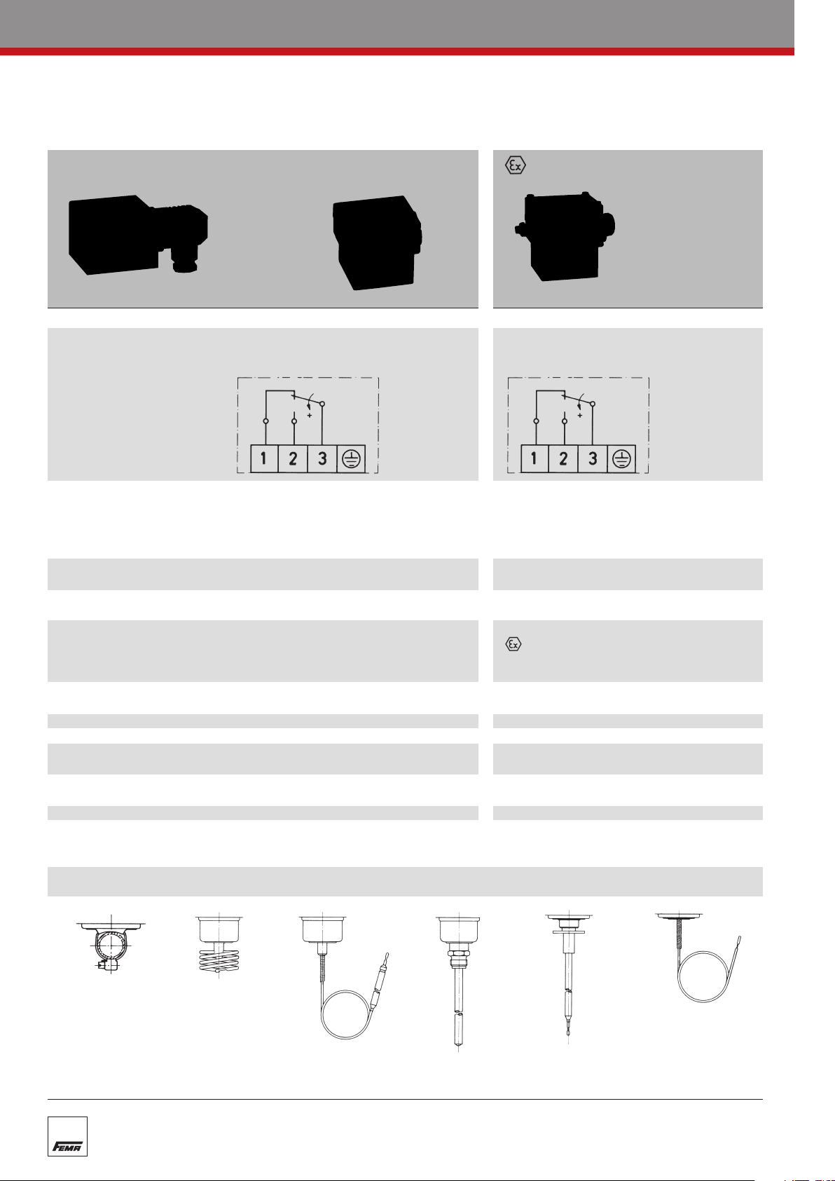
Room sensor
TRM
Strap-on sensor
TKM
Capillary tube sensor
T
AM
Rod sensor
TX + R 1
Air duct sensor
TX + R 6
Frost protection sensor
FT
Standard version Terminal connection -version
…200 …300 …700
Switch housing
Diecast aluminIum GDAISi 12 Diecast aluminIum GDAISi 12
Switching function Floating change-over contact Floating changeover contact.
and connection drawing With rising pressure switching single-pole With rising pressure switching single-pole
(applies only to version from 3–1 to 3–2 from 3–1 to 3–2
with microswitch)
Switching capacity 8 A at 250 VAC 3 A at 250 VAC
(applies only to version 5 A at 250 VAC inductive 2 A at 250 VAC inductive
with microswitch) 8 A at 24 VDC 3 A at 24 VDC
0.3 A at 250 VDC 0.03 A at 250 VDC
min. 10 mA, 12 VDC min. 2 mA, 24 VDC
Mounting position vertical or horizontal vertical
preferably vertical
Degree of protection IP 54 (terminal connection IP 65) IP 65
(in vertical position)
Explosion protection – EEx de IIC T6
Code – II 2 G D EEx de IIC T6 IP65 T80° C
EC T
ype Examination –
PTB 02 A
TEX 1121
Certificate Number
Electrical connection
Plug connection to DIN 43650/ Terminal connection
Terminal connection
Cable entr
y
PG 11 / for ter
minal connection M 16 x 1.5
M 16 x 1.5
Ambient temperature -15 to +70 °C -15 to +60 °C
Switching point Adjustable with spindle. Adjustable with spindle after
the terminal box lid is removed.
Switching differential Adjustable or not adjustable Not adjustable
(see Product Summary)
Medium temperatur
e
Max. 70
°
C, briefly 85
°
C
Max. 60 °C
Vibration strength No significant deviations up to 4 g.
At higher accelerations the switching differential is reduced slightly.
Use over 25 g is not per
mitted.
Isolation values Overvoltage category III, contamination class 3, reference surge voltage 4000 V.
Confor
mity to DIN VDE 0110 (01.89) is confir
med.
Sensor systems
 Loading...