


 Loading...
Honeywell F200e1037, F200e, F200e1011, F200e1029, F200e1003 Product Data
...
F200 Charged-Media Air Cleaner
PRODUCT DATA
APPLICATION
The F200 Charged-Media Air Cleaner captures a significant amount of the air-borne particles from the air circulated through the unit.
FEATURES
• Charged-Media filter captures particles as small as 0.3 micron.
• Efficiency ratings based on the American Society of Heating, Refrigerating and Air Conditioning Engineers Standard 52.2-1999.
• Applicable to all gas, oil, and electric forced warm air furnaces and to compressor cooling up to 5 tons.
• Mounts in the return air duct.
• Cabinet can support weight of residential furnace and evaporator coil.
• Requires no electrical connections.
• Mounts in any position.
• Requires no maintenance except periodic battery and media filter replacement.
• Quick and easy media filter replacement.
• Later upgrade to electronic air cleaner is easy.
• Integral pressure sensors signal when filter change is required based on increased pressure drop threshold at filter.
• Filter change status is transmitted to wall-mounted AIRWATCH® Indicator.
• The RF AIRWATCH® Indicator is included.
|
Contents |
Application/Features.......................................................... |
1 |
Specifications/Ordering Information .................................. |
2 |
Installation ......................................................................... |
7 |
Checkout ........................................................................... |
9 |
Parts List ........................................................................... |
10 |
68-0238EF-2
F200 CHARGED-MEDIA AIR CLEANER
SPECIFICATIONS
IMPORTANT
The specifications in this publication do not include normal manufacturing tolerances; therefore, an individual unit may not exactly match the listed specifications. This product is tested and calibrated under closely controlled conditions, and some minor differences in performance can be expected if those conditions are changed.
Model:
F200E Charged-Media Air Cleaner includes a cabinet, access door and pleated media filter, and an RF AIRWATCH® Indicator.
Application:
Use with gas, oil, and electric forced warm air furnaces and with compressor cooling. Can be used with heat pumps if filter is changed regularly to prevent excessive pressure drop.
Efficiency:
Efficiency Ratings: Based on American Society of Heating, Refrigerating and Air-Conditioning Engineers Standard 52.2- 1999. Efficiency ranges are defined for small particles, E1=0.3 to 1.0 microns; medium particles, E2=1.0 to 3.0 microns; and large particles, E3=3.0 to 10.0 microns.
Initial Efficiency:
E1=66%
E2=91%
E3=98%
Minimum Efficiency Reporting Valve (MERV): 13 at 492 fpm.
Filter Media: Pleated for greater media capacity.
Filter Element: Underwriters Laboratories, Inc.: UL 900,
Class 2 Listed.
Pressure Drop: See Fig. 3.
Initial Pressure Drop: 0.28 in. wc at 492 fpm.
Temperature Rating: -40° to +140°F (-40° to +60°C).
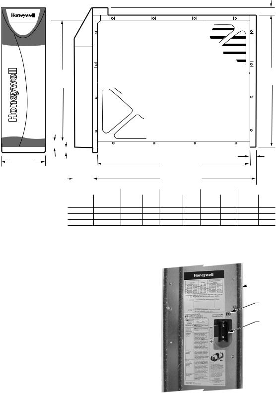
Dimensions: See Fig. 1.
Mounting:
Mounts in any position in the return air duct, usually next to the furnace blower compartment. Cabinet is sturdy enough to support weight of a residential furnace and evaporator coil.
Upgrade Path:
The F200 uses the same cabinet as the F300 Electronic Air Cleaner. Upgrade may require installing the cell key, electronic cells, protective screens and installation and wiring of the power box, depending on model.
ORDERING INFORMATION
When purchasing replacement and modernization products from your TRADELINE® wholesaler or distributor, refer to the TRADELINE® Catalog or price sheets for complete ordering number.
If you have additional questions, need further information, or would like to comment on our products or services, please write or phone:
1.Your local Honeywell Automation and Control Products Sales Office (check white pages of your phone directory).
2.Honeywell Customer Care 1885 Douglas Drive North
Minneapolis, Minnesota 55422-4386
In Canada—Honeywell Limited/Honeywell Limitée, 35 Dynamic Drive, Scarborough, Ontario M1V 4Z9.
International Sales and Service Offices in all principal cities of the world. Manufacturing in Australia, Canada, Finland, France, Germany, Japan, Mexico, Netherlands, Spain, Taiwan, United Kingdom, U.S.A.
68-0238EF—2 |
2 |
F200 CHARGED-MEDIA AIR CLEANER
.
1-1/8 (29)
DIM. A |
DIM. B |
|
(SEE |
||
(SEE TABLE) |
||
TABLE) |
||
|
|
7/8 |
|
|
|
|
|
|
|
|
|
|
|
|
|
|
|
|
|
|
|
|
|
|
|
|
|
|
|
|
|
|
|
|
|
|
|
|
|
|
|
|
|
|
|
|
|
|
|
|
|
|
|
|
|
|
|
|
|
|
|
|
|
|
|
|
|
|
|
|
||
|
|
|
|
|
|
|
|
|
|
|
|
|
|
|
|
|
|
|
|
|
|
|
|
|
|
|
|
|
|
|
|
|
|
||
|
|
|
|
|
|
|
|
|
|
|
|
|
|
|
|
|
|
|
|
|
|
|
|
|
|
|
|
|
|
|
|
|
|
||
|
|
|
|
|
|
|
|
|
|
|
|
|
|
|
|
|
|
|
|
|
|
|
|
|
|
|
|
|
|
|
|
|
|
||
|
|
|
|
|
|
|
|
|
|
|
|
|
|
|
|
|
|
|
|
|
|
|
|
|
|
|
|
|
|
|
|
|
|
||
|
(22) |
|
|
|
|
|
|
|
|
|
|
|
|
|
|
|
|
|
|
|
|
|
|
|
|
|
|
|
|
|
|
|
|
|
|
|
|
|
|
|
|
|
|
|
|
|
|
|
|
|
|
|
|
|
|
|
|
|
|
|
|
|
|
|
|
|
|
|
|
7/8 |
|
|
|
|
|
|
|
|
|
|
|
|
|
|
|
|
|
|
|
|
|
|
|
|
|
|
|
|
|
|
|
|
|
|
|
||
|
|
|
|
|
|
|
|
|
|
|
|
|
|
|
|
|
|
|
|
|
|
|
|
|
|
|
|
|
|
|
|
|
|
||
|
|
|
|
|
|
|
|
|
|
|
|
|
|
|
|
|
|
|
|
|
|
|
|
|
|
|
|
|
|
|
|
|
|
||
|
|
|
|
|
|
|
|
|
|
|
|
|
|
|
|
|
|
|
|
|
|
|
|
|
|
|
|
|
|
|
|
|
|
||
|
|
|
|
|
|
|
|
|
|
|
|
|
|
|
|
|
|
|
|
|
|
|
|
|
|
|
|
|
|
|
|
|
|
||
6-3/4 (171) |
5/8 |
|
|
|
|
|
|
|
|
|
|
|
|
|
|
|
|
|
|
|
|
|
|
|
|
|
|
|
|
|
(22) |
||||
|
|
|
|
|
|
|
|
|
|
|
|
|
|
|
|
|
|
|
|
DIM. C (SEE TABLE) |
|
|
|
|
|
|
|
||||||||
|
(16) |
|
|
|
|
|
|
|
|
|
|
|
|
|
|
|
|
|
|
|
|
|
|
|
|
|
|
|
|||||||
|
|
|
|
|
|
|
|
|
|
|
|
|
|
|
|
|
|
|
|
|
|
|
|
|
|
|
|
|
|
|
|
||||
|
|
2-1/2 |
|
|
|
|
|
|
|
|
|
|
|
|
|
|
|
|
|
|
DIM. D (SEE TABLE) |
|
|
|
|
|
|
|
|||||||
|
|
(63) |
|
|
|
|
|
|
|
|
|
|
|
|
|
|
|
|
|
|
|
|
|
|
|
|
|
|
|
|
|
||||
|
|
|
|
|
|
|
|
|
|
|
|
|
|
|
|
|
|
|
|
|
|
|
|
|
|
|
|
|
|
|
|
|
|
|
|
|
|
|
|
|
|
F200E SIZE |
|
|
|
DIM. A |
|
|
|
DIM. B |
|
|
|
DIM. C |
|
|
|
|
DIM. D |
||||||||||||
|
|
|
|
|
|
IN. |
|
|
MM |
|
|
IN. |
MM |
IN. |
MM |
IN. |
MM |
IN. |
|
MM |
|||||||||||||||
|
|
|
|
16 X 25 |
|
406 X 635 |
14 7/16 |
|
367 |
16 3/16 |
411 |
|
23 1/4 |
591 |
|
25 |
648 |
||||||||||||||||||
|
|
|
|
16 X 20 |
|
406 X 508 |
14 7/16 |
|
367 |
16 3/16 |
411 |
|
18 1/4 |
457 |
|
20 |
521 |
||||||||||||||||||
|
|
|
|
20 X 25 |
|
508 X 635 |
18 7/16 |
|
468 |
20 3/16 |
513 |
|
23 1/4 |
591 |
|
25 |
648 |
||||||||||||||||||
|
|
|
|
20 X 20 |
|
508 X 508 |
18 7/16 |
|
468 |
20 3/16 |
513 |
|
18 1/4 |
457 |
|
20 |
521 |
||||||||||||||||||
|
|
|
|
|
|
|
|
|
|
|
|
|
|
|
|
|
|
|
|
|
|
|
|
|
|
|
|
|
|
|
|
|
|
|
|
M14784A
Fig. 1. Installation dimensions in in. (mm) of air cleaner.
Media Replacement:
Replace the filter at least annually or when the built-in pressure sensors in the F200 door detect that airflow is impaired and the filter requires cleaning. This condition causes the indicator light on the F200 door to begin flashing and the transmitter to send a signal to the wall-mounted RF Indicator that the filter needs replacing.
After replacing the filter, press the reset button on the F200 door to reset both the door indicator light and the RF AIRWATCH® Air Cleaner Indicator. See Fig. 2. (See Table 1 for AIRWATCH® operation.)
 BACK SIDE OF DOOR
RESET BUTTON
BATTERY
M14864
Fig. 2. RF transmitter door - interior view.
3 |
68-0238EF—2 |
F200 CHARGED-MEDIA AIR CLEANER
16 x 25 in.
(406 x 635 mm)
20 x 20 in.
(508 x 508 mm)
|
0.4 |
|
|
|
|
|
|
|
|
|
|
|
|
|
|
|
|
|
|
|
|
|
|
|
|
|
|
|
|
|
|
|
|
|
|
|
1 |
|
|
|
|
16 x 20 in. |
|
|
|
|
|
|
|
|
|
|
(406 x 508 mm) |
|
|
|
|
||
|
|
|
|
|
|
|
|
|
|
||
(IN. WC) |
0.3 |
|
|
|
|
|
|
|
|
|
|
|
|
|
|
|
|
20 x 25 in. |
|
|
|||
|
|
|
|
|
|
|
|
|
|||
DROP |
0.2 |
|
|
|
|
|
|
|
|
||
PRESSURE |
|
|
|
|
|
|
|
(508 x 635 mm) |
|
|
|
0.1 |
|
|
|
|
|
|
|
|
|
|
|
|
|
|
|
|
|
|
|
|
|
||
|
|
|
|
|
|
|
|
|
|
|
|
|
0 |
|
|
|
|
|
|
|
|
|
|
|
|
|
|
|
|
|
|
|
|
|
|
|
0 |
500 |
1000 |
1500 |
2000 |
||||||
|
|
|
|
|
|
AIRFLOW (CFM) |
|
|
|
|
|
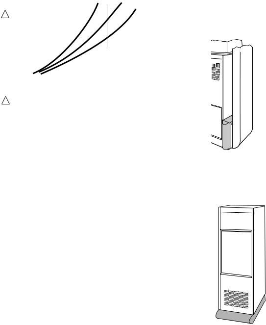
1WHEN FIRST INSTALLED. PRESSURE DROP INCREASES AS FILTER BECOMES LOADED. REPLACE FILTER WHEN PRESSURE DROP
REACHES 0.5 IN. WC. (0.1 kPa). |
M13662 |
|
Fig. 3. Capacity, Pressure Drop and Area of F200 Filter
Media.
PLANNING THE INSTALLATION
Location
The media air cleaner should be installed where all the air passing through the system is circulated through it. The best location is in the return air duct next to the blower compartment so the media air cleaner can help to keep the blower motor and evaporator coils clean. Do not mount in the supply air duct.
For most efficient air cleaning, spread airflow evenly across the face of the media. If the duct is a different size than the media air filter cabinet, gradual transitions are required. If the duct turns sharply just before the air filter, turning vanes are required.
Choose a location that is readily accessible for checking and replacing the filter. Allow at least 26 in. (660 mm) clearance in front of the unit for removal of the cartridge.
Install the media air filter where the temperature will not exceed the ratings in the Specifications.
Applications With Air Conditioning
Mount the media air cleaner upstream of the evaporator coil in a cooling system. The filter will help to keep the coil clean and reduce maintenance.
Applications With A Humidifier
The media air cleaner is compatible with humidifiers. Avoid applications where water mist will reach the media. If an atomizing humidifier is used, the filter media will require replacement more often because of minerals in the water.
Choose Mounting Position
The media air cleaner can be mounted in any position, but the arrow on the cartridge must point in the same direction as the airflow. See Figs. 4-11 for proper location of the media air cleaner for a variety of furnace installations. Note that the media air cleaner cabinet is sturdy enough to easily support the weight of the furnace and evaporator coil. See Fig. 5.
M14786
Fig. 4. Highboy furnace, with side installation. Media air filter is mounted vertically where return enters side inlet of furnace.
M14787
Fig. 5. Media air cleaner is mounted horizontally where return enters from below.
68-0238EF—2 |
4 |

F200 CHARGED-MEDIA AIR CLEANER
M941A
Fig. 6. Highboy furnace, with closet installation. Media air cleaner is mounted vertically on furnace between furnace and louvered return air opening in closet door.
M14788
Fig. 7. Lowboy furnace, with media air cleaner mounted horizontally in return plenum just above furnace and opposite heating plenum.
M14789
Fig. 8. Counterflow furnace, with media air cleaner mounted horizontally in return duct or plenum just above furnace.
M14790
Fig. 9. Central fan installation, with media air cleaner mounted horizontally in central return duct.
5 |
68-0238EF—2 |
F200 CHARGED-MEDIA AIR CLEANER
M14792
Fig. 10. Horizontal furnace, with media air filter mounted vertically in return duct near furnace.
NOTE: When more than one media air cleaner is used, each air cleaner requires a separate RF AIRWATCH®, if communication is desired with all units.
M14793
Fig. 11. Two or more media air cleaners used in a high capacity system.
Determining Sheetmetal Requirements
The media air cleaner is adaptable to all new or existing forced air heating and cooling systems used in residential applications. Transitions or turning vanes may be required in some applications for effective media air cleaner operation.
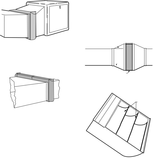
Transitions
Transitions are needed when the duct is a different size than the media air cleaner cabinet. Follow these guidelines when fabricating:
1.Use gradual transitions to reduce air turbulence and increase efficiency. See Fig. 12.
2.Use no more than 20 degrees (about 4 in. per running ft. (100 mm per 300 linear mm)) of expansion on each side of a transition fitting.
Turning Vanes
If the media air cleaner is installed next to an elbow or angle fitting, add turning vanes inside the angle to distribute airflow more evenly across the face of the media. See Fig 13.
Offsets
If the duct connection to the furnace in a side installation allows less than 7 in. (178 mm) for mounting media air cleaner cabinet, attach an offset to the elbow. See Fig. 14.
DUCT SIZE CHANGED GRADUALLY TO PREVENT TURBULENCE.
20 DEGREE EXPANSION PER SIDE PER FITTING (4 IN. PER RUNNING FOOT [100 MM PER 300 LINEAR MM]) 

RETURN AIR
DUCT
TRANSITION FITTING 
MEDIA AIR CLEANER CABINET |
M947B |
Fig. 12. Duct size changed gradually to prevent turbulence.
TURNING
VANES
M5651
Fig. 13. Turning vanes installed in bend help distribute airflow evenly over face of media.
68-0238EF—2 |
6 |
Loading...