


EW447-EW452 Series
Mechanical Heat Meters
FOR HEATING AND COOLING APPLICATIONS
PRODUCT DATA
Application
Design
Hydronic meters of the EW447-452 Series consist of:
•Electronic energy integrator with fixed cable connection to the volume measuring component, supply and return temperature probe
•Mechanical volume measuring component with external threads according to ISO228 (DN15...DN40) or flanges (DN25…DN100)
Materials
•Housing of electronic energy integrator made of plastic
•Housing of mechanical volume measuring component made of brass (EW447, EW448, EW450 and EW451) or of cast iron (EW449 and EW452)
Static compact heat meter with electronic measurement, consisting of electronic energy integrator and mechanical volume measuring component.
Metering of hydronic heating and / or cooling energy in hydronic systems based on volume, supply and return temperature. EW447-EW449 models are suitable for energy metering of heating systems.
EW450-EW452 models are suitable for energy metering of cooling and combined cooling and heating systems.
Features
•Electronic sensor control for recording flow rate
•Nominal size qp 0.6 to qp 60 m3/h
•Model 447/450 with direct electronic impeller scanning Model 448/449/451/452 with magnetic coupling for electronic scanning of sensor disc
•Lithium battery guarantees longer lifetime than calibration interval
•Optical ZVEI interface equipped as standard
•Primary interface
•Optional: M-Bus interface to EN 1434-3
•Optional: Pulse output for energy and volume for heat
meter
Pulse output for cold and heat energy in cooling & heat meter (open-collector)
•Adjustable reading date for billing
•Rotatable integrator
•RF version in preparation
Software
Hydro-Set software parametrization tool based on M-Bus and optical interface for
•Readout of measured values
•18 final monthly values
•Value on readout date
•Error log
•Total down time
•Max. power
•Max. flow rate
•Max. temperature
•Operating hours
•Etc.
•Printing meter logs
•Meter configuration
•Readout date
•Primary address
•Limits for cooling & heat meter
•Reset of max. values
Honeywell y Subject to change |
EN0H-2601GE25 R0809 |

EW447-EW452 SERIES MECHANICAL HEAT METERS
Specifications
|
Table 1. Specifications |
Medium |
Water quality to VDI2035 |
Medium temperature |
5…90°C (41…194°F) |
Ambient temperature |
5…55°C (41...131°F) - PTB approval |
Operating pressure |
PN16 |
kvs(cv)-values |
see table below |
Ambient class |
EN1434 class C |
Protection class |
IP54 |
Type |
Compact heatmeter to EN1434 |
Measuring process |
EW447/EW450: direct electronic impeller scanning |
|
EW448/EW449/EW451/EW452: multijet impeller scanning via magnetic coupling |
|
with sensors |
Display |
LCD, 7-digit |
Units |
MWh - kWh - GJ - MJ - kW - m³/h - l/h - m³ - l |
Total values |
9 999 999 - 999 999.9 - 99 999.99 - 9 999.999 |
Values displayed |
Power - Energy - Flow rate - Temperature |
Temperature sensors |
Pt500 with 2-wire leads |
Sensor current |
Pt500 peak < 2; rms 0,012 mA |
Measuring cycle |
32s |
Max. measurable temperature difference |
147K |
Min. measurable temperature difference |
3K |
Energy billing from |
0.25K |
Absolute temperature measuring range |
0…150°C |
(integrator) |
|
Operating voltage |
3.0V lithium battery |
|
|
|
|
Table 2. |
Specifications |
|
|
|
|
|
|||
|
Series |
EW447/EW450 |
|
EW448/EW451 |
|
EW449/EW452 |
|
||||||
|
qp |
0.6 |
1.5 |
|
2.5 |
|
3.5 |
6 |
10 |
15 |
25 |
40 |
60 |
Maximum (qs) |
m3/h |
1.2 |
3 |
|
5 |
|
7 |
12 |
20 |
50 |
50 |
110 |
140 |
Nominal (qp) |
m3/h |
0.6 |
1.5 |
|
2.5 |
|
3.5 |
6 |
10 |
15 |
25 |
40 |
60 |
Minimum (qi) |
l/h |
6 |
15 |
|
25 |
|
70 |
120 |
200 |
300 |
500 |
800 |
1200 |
Starting |
l/h |
2 |
4 |
|
6 |
|
35 |
60 |
100 |
60 |
60 |
90 |
90 |
kvs (cv)-value |
m3/h |
1.22 |
3.04 |
|
5.08 |
|
7 |
12 |
20 |
60 |
66 |
141 |
190 |
∆p at qp |
mbar |
243 |
243 |
|
242 |
|
250 |
250 |
250 |
62 |
142 |
80 |
100 |
Function
Integrator
The integrator contains all the necessary circuits for recording flow rate and temperature and for calculating, logging and displaying the data. The meter can be conveniently read from a single line seven-digit display with units and symbols. A pushbutton provides user friendly control of the various display loops. All failures and faults are recorded automatically and displayed on the LCD screen. To protect the reading data, all relevant data is saved in a non-volatile memory (EEPROM). This memory saves the measured values, device parameters and types of error at regular intervals.
Mechanical volume measuring component
The technology of the volume measuring component permits very high measuring accuracy and can be used in the supply or return pipeline. The volume measuring component meets the requirements of EN1434 / class 2 and 3.
Supply voltage:
• Lithium battery 3.0 V DC (10-year life)
Temperature sensors
Pt500 type temperature sensors to DIN EN 60751 are used as standard.
The temperature sensors are permanently connected to the integrator. They have the following cable lengths:
EW447/EW450 |
0.4m with sensor installed in volume |
|
measuring housing |
|
1.5m for sensor installation in corre- |
|
sponding supply/return pipe |
|
|
EW448/EW451 |
1.5m with sensor installed in volume |
|
measuring housing |
|
3m for sensor installation in corre- |
|
sponding supply/return pipe |
|
|
EW449/EW452 |
2 x 6m for sensor installation in supply |
|
and corresponding return pipe |
|
|
EN0H-2601GE25 R0809 |
2 |
Honeywell y Subject to change |
EW447-EW452 SERIES MECHANICAL HEAT METERS
Ordering Information
Table 3. Available versions and OS-Nos (OS=Ordering Specification)
Size qp |
Size DN |
Length |
Connection |
Interface |
OS-No. |
OS-No. |
|
|
|
|
|
(heating only) |
(cooling and |
|
|
|
|
|
|
heating) |
0.6 m3/h |
DN15 |
110 mm |
G 3/4 B |
None |
EW447A0100 |
EW450A0100 |
1.5 m3/h |
DN15 |
110 mm |
G 3/4 B |
None |
EW447A1200 |
EW450A1200 |
2.5 m3/h |
DN20 |
130 mm |
G 1 B |
None |
EW447A2000 |
EW450A2000 |
3.5 m3/h |
DN25 |
260 mm |
G 1 1/4 B |
None |
EW448A2800 |
EW451A2800 |
6.0 m3/h |
DN25 |
260 mm |
G 1 1/4 B |
None |
EW448A3600 |
EW451A3600 |
10 m3/h |
DN40 |
300 mm |
G 2 B |
None |
EW448A4600 |
EW451A4600 |
15 m3/h |
DN50 |
270 mm |
Flanges PN16 |
None |
EW449A5100 |
EW452A5100 |
25 m3/h |
DN65 |
300 mm |
Flanges PN16 |
None |
EW449A5900 |
EW452A5900 |
40 m3/h |
DN80 |
300 mm |
Flanges PN16 |
None |
EW449A6900 |
EW452A6900 |
60 m3/h |
DN100 |
360 mm |
Flanges PN16 |
None |
EW449A7700 |
EW452A7700 |
With M-Bus output |
|
|
|
|
|
|
0.6 m3/h |
DN15 |
110 mm |
G 3/4 B |
M-Bus |
EW447M0100 |
EW450M0100 |
1.5 m3/h |
DN15 |
110 mm |
G 3/4 B |
M-Bus |
EW447M1200 |
EW450M1200 |
2.5 m3/h |
DN20 |
130 mm |
G 1 B |
M-Bus |
EW447M2000 |
EW450M2000 |
3.5 m3/h |
DN25 |
260 mm |
G 1 1/4 B |
M-Bus |
EW448M2800 |
EW451M2800 |
6.0 m3/h |
DN25 |
260 mm |
G 1 1/4 B |
M-Bus |
EW448M3600 |
EW451M3600 |
10 m3/h |
DN40 |
300 mm |
G 2 B |
M-Bus |
EW448M4600 |
EW451M4600 |
15 m3/h |
DN50 |
270 mm |
Flanges PN16 |
M-Bus |
EW449M5100 |
EW452M5100 |
25 m3/h |
DN65 |
300 mm |
Flanges PN16 |
M-Bus |
EW449M5900 |
EW452M5900 |
40 m3/h |
DN80 |
300 mm |
Flanges PN16 |
M-Bus |
EW449M6900 |
EW452M6900 |
60 m3/h |
DN100 |
360 mm |
Flanges PN16 |
M-Bus |
EW449M7700 |
EW452M7700 |
With pulse output |
|
|
|
|
|
|
0.6 m3/h |
DN15 |
110 mm |
G 3/4 B |
Pulse output |
EW447P0100 |
EW450P0100 |
1.5 m3/h |
DN15 |
110 mm |
G 3/4 B |
Pulse output |
EW447P1200 |
EW450P1200 |
2.5 m3/h |
DN20 |
130 mm |
G 1 B |
Pulse output |
EW447P2000 |
EW450P2000 |
3.5 m3/h |
DN25 |
260 mm |
G 1 1/4 B |
Pulse output |
EW448P2800 |
EW451P2800 |
6.0 m3/h |
DN25 |
260 mm |
G 1 1/4 B |
Pulse output |
EW448P3600 |
EW451P3600 |
10 m3³/h |
DN40 |
300 mm |
G 2 B |
Pulse output |
EW448P4600 |
EW451P4600 |
15 m3/h |
DN50 |
270 mm |
Flanges PN16 |
Pulse output |
EW449P5100 |
EW452P5100 |
25 m3/h |
DN65 |
300 mm |
Flanges PN16 |
Pulse output |
EW449P5900 |
EW452P5900 |
40 m3/h |
DN80 |
300 mm |
Flanges PN16 |
Pulse output |
EW449P6900 |
EW452P6900 |
60 m3/h |
DN100 |
360 mm |
Flanges PN16 |
Pulse output |
EW449P7700 |
EW452P7700 |
Operation |
|
|
Loop Overview |
|
|
|
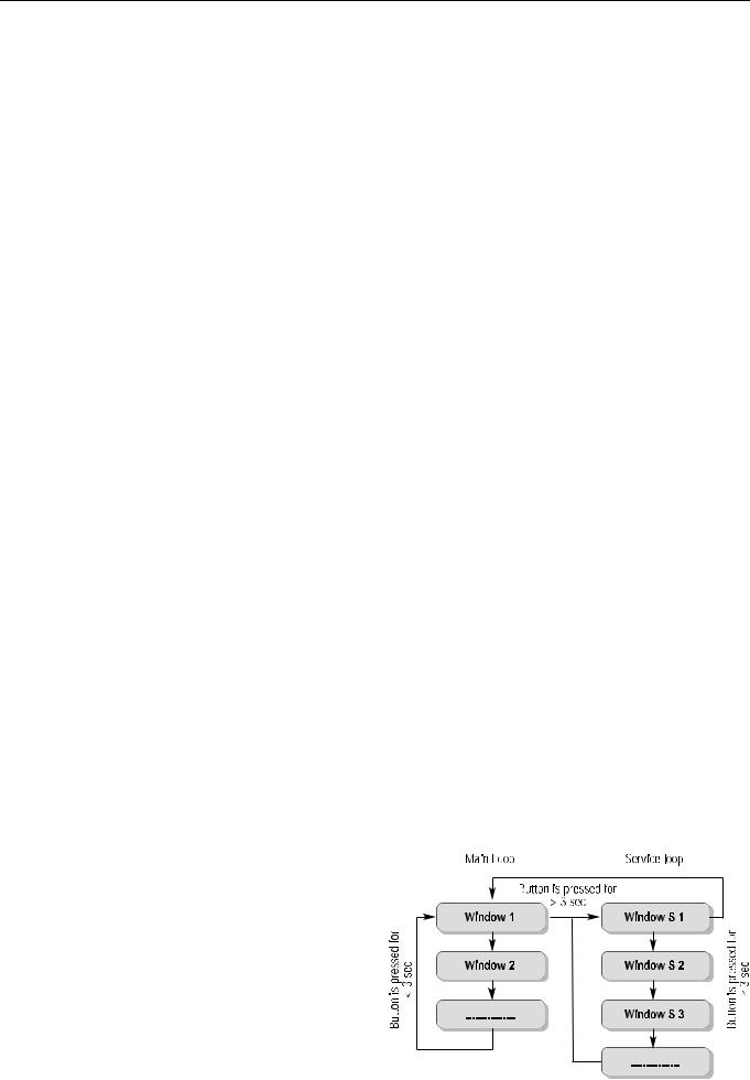
The integrator display has two loops.
• Main loop
• Service loop
The main loop is configured to display the data for current energy and energy on reading date. The service loop displays the current data for flow rate, temperatures, power, volume and next reading date.
A button is mounted on the front panel of the meter. This can be pressed for a short or long time. A short press of the button (< 3 seconds) switches to the next display within a loop and a long press (> 3 seconds) switches between the display loops.
NOTE: The LC display has a power save mode, which is activated by pressing a button. The display switches off automatically and changes to the power save mode if the button is not pressed for 5 minutes.
Honeywell y Subject to change |
3 |
EN0H-2601GE25 R0809 |
 Loading...