


Excel 100/500/600
CONTROLLERS
HONEYWELL EXCEL 5000 OPEN SYSTEM
SYSTEM OVERVIEW
Copyright © 2008 Honeywell Inc. • All Rights Reserved |
EN0B-0091GE51 R0708 |

EXCEL 100/500/600 – SYSTEM OVERVIEW
EBI/SymmetrE
REPORT PRINTER |
|
|
|
|
|
|
|
|
|
ALARM PRINTER |
|||
|
|
|
|
|
|
|
|
||||||
|
|
|
|
|
|
|
|
|
|
|
|
|
|
|
|
|
|
|
|
|
|
|
|
|
|
|
|
|
|
|
|
|
|
|
|
|
|
|
|
|
|
|
|
|
|
|
|
|
|
|
|
|
|
|
|
XW570
C-BUS
|
|
|
|
|
|
|
|
|
|
|
|
|
|
|
|
|
|
LOCAL |
LonWorks |
|
|||||||||
|
|
|
modem / |
|||||||||||
|
|
|
LonWorks |
|
|
|
|
|
|
|
|
|
|
ISND adapter |
|
|
|
|
|
|
|
|
|
|
|
|
|
||
|
|
|
NETWORK |
|
|
|
|
|
|
|
|
|
|
|
|
|
|
|
|
|
|
|
|
|
|
|
|
|
|
|
|
|
|
|
|
|
|
|
|
|
|
|
|
|
|
|
|
|
|
|
|
|
|
|
|
|
|
|
|
|
|
|
|
|
|
|
|
|
|
|
|
|
|
|
|
|
|
|
|
|
|
|
|
|
|
|
|
|
|
Excel 500
XC5010C
|
|
|
|
|
|
|
Excel 50 |
modem / |
modem / |
|||
|
|
|
|
|
|
|
||||||
|
|
|
|
|
|
|
|
|
|
ISND adapter |
ISND adapter |
|
|
|
|
DISTRIBUTED |
|
|
|
||||||
|
|
|
|
|
I/Os |
|
|
|
|
|
|
|
|
|
|
|
|
|
|
|
|
|
|
||
|
|
|
|
|
|
|
|
|
|
|
|
|
|
|
|
|
|
|
|
|
|
|
|
|
|
|
|
|
|
|
|
|
|
|
|
|
|
|
Excel 600 |
Excel 500 |
|
|
XC5010C |
|
|
Excel 500 |
Excel 500 |
|
XC5010C |
XC5210C |
Excel 800 |
EXCEL 800
I/Os
Excel 10 Chilled
Ceiling Controller
3rd-party LonWorks products
LonWorks
3rd-party LonWorks products
DISTRIBUTED I/Os
Excel 20
DISTRIBUTED I/Os
DISTRIBUTED
I/Os
Excel 10 Fan Coil Controller
|
LOCAL |
|
|
Excel 500 |
LonWorks |
Excel 500 |
Excel 500 |
NETWORK |
|||
XCL5010 |
|
XCL5010 |
XCL5010 |
|
|
EXCEL 5000 system |
|
EN0B-0091GE51 R0708

EXCEL 100/500/600 – SYSTEM OVERVIEW |
|
|
CONTENTS |
REVISION OVERVIEW.................................................................................................................................................................. |
ii |
THE EXCEL 100/500/600 SYSTEM............................................................................................................................................... |
1 |
The User Programs ................................................................................................... |
2 |
Excel 100 Modules .................................................................................................... |
3 |
Excel 100 Technical Data.......................................................................................... |
3 |
The Excel 500–XCL5010........................................................................................... |
4 |
The Excel 500/600 Internal Modules (not XCL5010) ................................................. |
4 |
XC5010C Computer Module................................................................................ |
5 |
XC5210C Computer Module................................................................................ |
5 |
XC6010 Computer Module .................................................................................. |
5 |
XD505A / 508 Communication Submodules........................................................ |
5 |
XP502 Power Supply Module .............................................................................. |
6 |
XF521A Analog Input Module .............................................................................. |
6 |
XF526 Analog Input Module ................................................................................ |
6 |
XF522A Analog Output Module ........................................................................... |
7 |
XF527 Analog Output Module.............................................................................. |
7 |
XF523A Digital Input Module ............................................................................... |
7 |
XF524A Digital Output Module ............................................................................ |
7 |
XF529 Digital Output Module............................................................................... |
7 |
XF525A Three-Position Output Module ............................................................... |
8 |
Summary of Internal Modules.................................................................................... |
9 |
Additional Parts ....................................................................................................... |
10 |
Distributed I/O Modules........................................................................................... |
11 |
Analog Input Module XFL521B .......................................................................... |
11 |
Analog Output Module XFL522B ....................................................................... |
12 |
Digital Input Module XFL523B ........................................................................... |
12 |
Digital Output Module XFL524B ........................................................................ |
12 |
Manual Override Unit XFR522A for XFL522A ................................................... |
12 |
Manual Override Unit XFR524A for XFL524A ................................................... |
13 |
Summary of Distributed I/O Modules....................................................................... |
13 |
Additional Parts ....................................................................................................... |
14 |
Excel Smart I/O Modules ................................................................................... |
14 |
Time Programs........................................................................................................ |
15 |
System Texts........................................................................................................... |
15 |
Installation and Commissioning............................................................................... |
15 |
Excel 500/600 Technical Data................................................................................. |
16 |
Remote Communication ............................................................................................................................................................ |
18 |
XI581 / XI582 OPERATOR UNIT ................................................................................................................................................. |
19 |
XL-Online .................................................................................................................................................................................... |
21 |
CARE ENGINEERING SYSTEM.................................................................................................................................................. |
23 |
Live CARE Monitoring and Simulation Tool ............................................................................................................................ |
25 |
Trademark Information Echelon, LON, LONMARK, LONWORKS, LonBuilder, NodeBuilder, LonManager, LonTalk, LonUsers, LonPoint, Neuron, 3120, 3150, the Echelon logo, the LONMARK logo, and the LonUsers logo are trademarks of Echelon Corporation registered in the United States and other countries. LonLink, LonResponse, LonSupport, and LonMaker are trademarks of Echelon Corporation.
i |
EN0B-0091GE51 R0708 |

CONTENTS |
EXCEL 100/500/600 – SYSTEM OVERVIEW |
REVISION OVERVIEW
The following pages have been changed from the previous release of this document:
Pages |
Changes |
throughout |
All references to GSM modem have been eliminated. Occurrences of XBS have been replaced with |
|
EBI/SymmetrE. |
EN0B-0091GE51 R0708 |
ii |

EXCEL 100/500/600 – SYSTEM OVERVIEW
THE EXCEL 100/500/600 SYSTEM
Excel 100/500/600 Excel 100/500/600 is a freely programmable control and monitoring system for building applications.
In addition to control applications for heating, ventilation and air conditioning, Excel 100/500/600 also performs energy management functions such as optimum start/stop, night purge, maximum load demand, and many others.
Freely programmable LONMARK The Excel 500 controller complies with the LONMARK ® Interoperability Guidelines. controller (Excel 500, only) It supports up to 512 NVs which can be mapped to data points. It can function on a
LONWORKS® network with Excel 10 and Excel 50 controllers, other Excel 500 controllers and their Distributed I/O modules, and third-party LONWORKS devices and centrals. The Excel 500 provides the following unique benefits:
Automatic binding of Excel 500 controllers and Honeywell I/O modules. This saves engineering time and cost over usual network variable (NV) binding. In addition, this saves on Echelon® node royalty fees.
512 NVs supported for integration and interoperation with other devices on the LONWORKS network.
NV-Booster® functionality avoids multiple NVs with many-to-one bindings and thus reduces the number of Excel 500 controllers needed.
All binding information from and to the Excel 500 controller can be saved in Flash memory or uploaded together with the application and restored after power failure. This also allows exchange of controller hardware without redoing the complete binding.
The Excel 500 controller allows conversion of NV types which increases flexibility and interoperability on a LONWORKS network.
With firmware 2.06.00 and higher, Excel 500 controllers support full Building Management Functionality (BMF) over LONWORKS (alarming, scheduling, trending).
Connection to building supervisors Up to eight building supervisors can be connected via the Honeywell system bus (C- Bus). Excel 100/500/600 allows communication with an EBI/SymmetrE building supervisor via modem or ISDN terminal adapter.
Communication via analog/ISDN modemExcel 500 (with firmware version 2.01.00 and higher) and Excel 100C allow direct connection of an analog modem or ISDN terminal adapter, with data transmission rates of up to 38.4 Kbaud.
Modular design and easy operation The modular design enables the system to be expanded to meet the growing needs of the building. The user addresses and the full English-language descriptors are stored in the controller and are, therefore, available to be viewed locally, at the operator unit, without the need for a central PC.
NOTE: The Excel 500-XCL5010 and the Excel 100C have no internal display; thus, an XI582 or an XL-Online is needed.
Distributed I/O modules and The modules consist of an electronic module and a terminal module. The terminal Excel Smart I/O modules connected module provides terminals for all field signals. Internal wiring between the Excel 500
via LONWORKS® bus controller and the field terminals is not required (except for the 2-wire LONWORKS bus connection). Optional manual override modules and manual disconnect modules are available.
Excel Smart I/O modules are LONMARK association-compliant devices, and are thus suitable for all LONWORKS environments. They feature a variety of softwareconfigurable digital and analog inputs and outputs and can be installed at strategic locations throughout buildings.
NOTE: The Excel 500-XCL5010 can be connected only to external I/O modules.
The connection of internal plug-in modules is not possible.
Large remote trend buffer The XC5210C Excel 500 CPU module provides an enlarged remote trend buffer which allows more than 10,000 historical values to be stored and transmitted to a building supervisor.
1 |
EN0B-0091GE51 R0708 |

EXCEL 100 SYSTEM |
EXCEL 100/500/600 – SYSTEM OVERVIEW |
The User Programs
Free selection of applications The Excel 100/500/600 receives its user programs in three different ways:
Permanent applications from EPROM With the selection of the applications for the EPROM, the user program is assembled from permanently programmed functions when starting the system for the first time – no further programming tools are necessary. With Flash-EPROM, applications can be stored restored via the operator interface.
Configurable applications With the CARE engineering system, standard applications for heating, ventilation and air conditioning technology can be assembled and extended as desired.
No programming experience needed With free program preparation using CARE, the user program is generated automatically after graphical preparation of the system schematic diagram, the instrumentation and control strategies.
EN0B-0091GE51 R0708 |
2 |
EXCEL 100/500/600 – SYSTEM OVERVIEW |
EXCEL 100/500/600 SYSTEM |
Excel 100 Modules
MCE 3 and MCE 1 The MCE 3 and MCE 1 are analog/digital converters that convert analog outputs of the Excel 100 into digital outputs. The MCE 1 converts one analog output into one voltage-free changeover contact. The MCE 3 converts three analog inputs into two voltage-free outputs and one N.O. contact.
MCD 3 The MCD 3 is an analog/digital converter that converts 1 analog output into one voltage-free changeover contact and one analog output into a three-point output.
MCM 1 The MCM 1 is a 4-channel separation module that provides active switching voltages to the digital inputs of the Excel 100 from up to four voltage-free contacts.
Excel 100 Technical Data
Voltage:
24 Vac, ± 20%, 50 to 60 Hz
24 Vdc, + 20%, – 10%
IMPORTANT
If the Excel 100C is supported with, e.g. a battery or accumulator, it has to be assured that no “pumping” of the power supply occurs.
Maximum number of devices per System Bus:
30
Power consumption: max. 40 VA (max. 30 W)
Ambient temperature:
During operation: 0 to 50°C (0 to 45°C when mounted horizontally) During storage: -20 to 60°C
Ambient humidity:
During operation and storage 5 to 90% r.h.
Dimensions of housing:
235 x 192 x 72 mm (H x W x D)
Mounting:
Wall or DIN rail mounting
Program back-up during power failure:
72 hours via gold capacitor
Protection class:
IP 30 (with cover mounted)
Operator units:
Operator unit XI582 desktop or wall mounting XL-Online
Table 1. Excel 100 Modules
module |
type |
hardware |
|
Analog/digital converter |
MCD 1 |
1 analog input for one voltage-free changeover contact |
|
Analog/digital converter |
MCD 3 |
1 analog input for one voltage-free changeover contact |
|
1 analog input for one three-point output |
|||
|
|
||
|
|
2 analog inputs for two voltage-free changeover |
|
Analog/digital converter |
MCE 3 |
contacts; 1 analog input for one voltage-free N.O. |
|
|
|
contact |
|
Separation module |
MCM 1 |
4 voltage-free contacts for 4 digital inputs |
3 |
EN0B-0091GE51 R0708 |
EXCEL 100/500/600 SYSTEM |
EXCEL 100/500/600 – SYSTEM OVERVIEW |
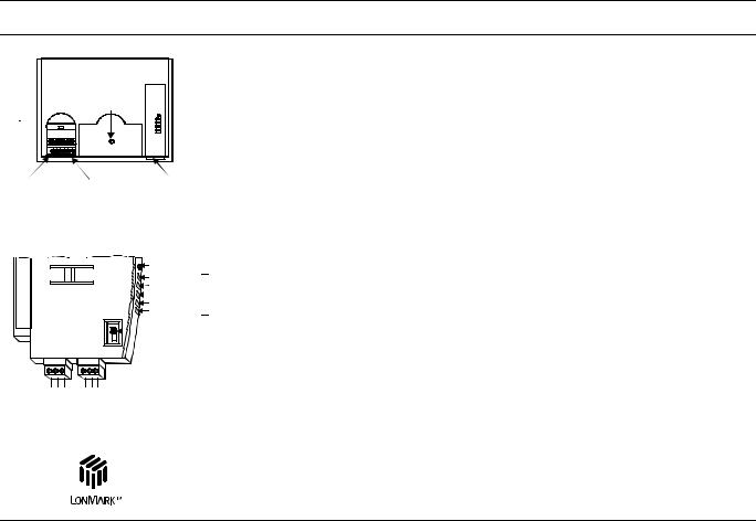
The Excel 500–XCL5010
|
|
|
|
|
|
|
|
|
|
|
|
|
|
|
|
|
|
|
|
|
|
|
|
|
|
|
Blk |
Excel 500 |
|
|
|
|
|||||||||||||||||||||||
|
|
|
|
|
|
|
Term |
||||||||||||||||||||
(XCL5010) |
|
|
|
|
|
|
|
||||||||||||||||||||
|
|
|
|
|
|
|
|
||||||||||||||||||||
|
|
|
|
|
|
|
|
|
|
|
RESET |
|
|
|
|
|
|
|
|
||||||||
|
|
|
|
|
|
|
|
|
|
BUTTON |
|
|
|
|
|
|
|
|
|||||||||
SCREW |
|
|
REMOVABLE FUSE |
COMMUNICATION |
|||
TERMINAL |
|
|
BELOW |
MODULE |
|
||
BLOCK |
|
|
TERMINAL BLOCK |
(REMOVABLE) |
|||
(REMOVABLE) |
|
|
|
|
|
||
|
|
XCL5010 Controller |
|
||||
|
|
|
|
|
LON SERVICE BUTTON |
||
|
|
|
|
|
POWER, GRN |
|
|
|
|
|
|
|
LON SERVICE, RED |
LEDs |
|
|
|
|
|
|
C-BUS TxD, YEL |
|
|
|
|
|
|
|
C-BUS RxD, YEL |
|
|
|
|
|
|
|
RESERVED |
|
|
|
|
|
|
|
C-BUS |
|
|
|
|
|
|
|
TERMINATION |
|
|
|
|
|
|
|
SWITCH |
|
|
1 |
2 |
3 |
4 |
5 |
6 |
|
|
LON |
|
|
|
|
C-BUS |
|
|
BUS |
A1 A2 |
NOT USED |
SHIELD C + C - |
|
00000124 |
||
|
|
||||||
Communication Module XDL505
The Excel 500–XCL5010 controller is specially designed for operation with Distributed I/O modules or Smart I/O modules via a LONWORKS bus. Control and monitoring functions are performed by means of programmable, 16-bit microprocessor controlled, digital technology. The Excel 500 System is freely programmable and can be used as a stand-alone controller or as part of a network of up to 30 controllers connected via a C-bus (9.6 Kbaud up to 76.8 Kbaud) or as part of an open LONWORKS network.
The Excel 500 System provides energy management and control functions in Honeywell C-Bus networks or in LONWORKS networks. In the case of a Honeywell C- Bus network, up to 16 Distributed I/O modules with up to 128 inputs and outputs can be connected. A maximum of 10 modules of the same type is allowed per system. In the case of a LONWORKS network, the maximum number of Distributed I/O modules is determined by the number of NVs needed for interoperation. In a typical case, 190 physical inputs and outputs can be controlled per Excel 500.
Applications for the Excel 500 can be programmed during CARE engineering and then downloaded in the Flash EPROM.
Memory is buffered by a gold capacitor and will be supported for approximately 72 hours in case of a power failure.
The XCL5010 controller comprises an internal power supply and allows the connection of CPU and I/O modules to the same transformer (shared transformer).
An external MMI, modem, or ISDN adapter can be connected to the controller’s serial port.
The Communication Module provides ports for C-bus and LONWORKS bus connection, as well as LEDs for indicating the controller's operational status, transmit status, and receive status.
|
The Excel 500/600 Internal Modules (not XCL5010) |
|
|
The Excel 500/600 system with internal modules is comprised of the XC5010C |
|
|
(Excel 500) or XC6010 (Excel 600) computer modules for freely programmable |
|
|
applications, the power supply module XP501 or XP502 with an external transformer |
|
|
as well as a range of input and output modules. |
|
Clear functional allocation |
The internal input and output modules are: |
|
|
Analog input modules |
XF521A / XF526 |
|
Analog output modules |
XF522A / XF527 |
|
Digital input modules |
XF523A / XF528 |
|
Digital output modules |
XF524A / XF529 |
|
Three-position output module |
XF525A |
One important functional characteristic of the output modules XF522A, XF524A and XF525A is the integral manual override facility to switch equipment and position actuators directly from the module. The output modules XF527 and XF529 are equipment variants without manual override switches. The status of the inputs and outputs is shown by LEDs.
An Excel 500/600 can consist of 16 input and output modules providing a total of 128 points. The system can be expanded by connecting additional controllers if the number of inputs and outputs is insufficient for a particular application. Communication is performed via the system bus.
In general, the maximum system bus length is 1200 meters. However, a bus repeater (XD509) is available to exceed this limit.
EN0B-0091GE51 R0708 |
4 |
EXCEL 100/500/600 – SYSTEM OVERVIEW |
EXCEL 100/500/600 SYSTEM |
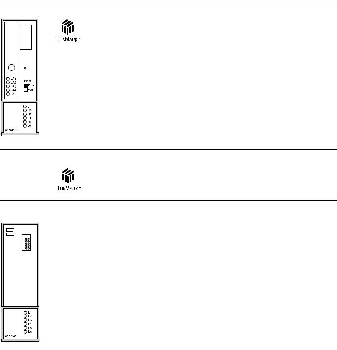
XC5010C Computer Module
The XC5010C computer module is the brain of Excel 500 and features internal modules. Control and monitoring functions are performed by means of programmable, 16-bit microprocessor controlled, digital technology. The program is held in RAM, but it can also be saved onto a Flash-EPROM. RAM is buffered by a gold capacitor and is supported for approx. 72 hours in case of a power failure.
The XC5010C adds support for a LONWORKS network connection to Distributed I/O modules and to other controllers and LONMARK devices. Serial interface communication support for MMI is possible via two interfaces, Sub-D (front) and 18-pin male (back), which can be selected using a switch on the front panel. The interface enables the system to be expanded to up to 30 devices including a building supervisor. Communication is performed via the system bus using a token-passing multi-master structure. LEDs indicate the operational status as well as the transmit / receive status of the interfaces.
XC5210C Computer Module
The XC5210C computer module has all the same functions and capabilities as the XC5010C described above with one exception. Increased memory allows for a greatly increased remote trend buffer capacity – up to 10,000 values can be stored.
XC6010 Computer Module
The XC6010 computer module is the 32-bit, high performance version of the XC5010C computer module. It features more memory and faster DCC cycle-times as well as faster scanning times in combination with some of the input / output modules.
The XC6010 computer module has only a single serial interface connection and does not support LONWORKS bus connections; therefore, Distributed I/O modules cannot be used with the XC6010C.
XD505A / 508 Communication Submodules
The submodules XD505A and XD508 are used for C-bus communication with older
Excel 100/500 and Excel 600 controllers. The submodules are plugged onto the
Excel 100B or XC5010B/XC6010 computer modules.
5 |
EN0B-0091GE51 R0708 |
 Loading...