


 Loading...
Excel 50/100/500/600/800
CONTROLLERS
HONEYWELL EXCEL 5000 OPEN SYSTEM
SOFTWARE DESCRIPTION
® U.S. Registered Trademark |
EN2B-0092GE51 R0709 |
Copyright © 2009 Honeywell Inc. • All rights reserved |
|

EXCEL 50/100/500/600/800
Trademark Information Echelon, LON, LONMARK, LONWORKS, LonBuilder, NodeBuilder, LonManager, LonTalk, LonUsers, LonPoint, Neuron, 3120, 3150, the Echelon logo, the LONMARK logo, and the LonUsers logo are trademarks of Echelon Corporation registered in the United States and other countries. LonLink, LonResponse, LonSupport, and LonMaker are trademarks of Echelon Corporation.
EN2B-0092GE51 R0709

EXCEL 50/100/500/600 |
|
|
CONTENTS |
Revision overview ........................................................................................................................................................................ |
5 |
System Overview.......................................................................................................................................................................... |
6 |
Datapoints..................................................................................................................................................................................... |
9 |
Physical Datapoints .................................................................................................. |
9 |
Flexible Datapoints ................................................................................................. |
10 |
Pseudo Datapoints ................................................................................................. |
10 |
Global Datapoints ................................................................................................... |
11 |
Mapped Datapoints (V2.04.xx or higher) ................................................................ |
12 |
Attributes .................................................................................................................................................................................... |
13 |
Access Level........................................................................................................... |
13 |
Acknowledge Alarm (V2.04.xx or higher)................................................................ |
13 |
Active State (prior to V2.04.x)................................................................................. |
14 |
Active State (Excel 800) ......................................................................................... |
14 |
Alarm Delay ............................................................................................................ |
15 |
Alarm Suppression ................................................................................................. |
15 |
Alarm Status (prior to V2.04.x)................................................................................ |
15 |
Alarm Status (V2.04.xx or higher)........................................................................... |
16 |
Alarm Type ............................................................................................................. |
16 |
Alarm Definition ...................................................................................................... |
17 |
Cycle Count ............................................................................................................ |
18 |
Delay Time Switching Up........................................................................................ |
18 |
Delay Time Switching Down ................................................................................... |
18 |
Descriptors ............................................................................................................. |
18 |
Engineering Unit ..................................................................................................... |
19 |
Feedback Delay...................................................................................................... |
19 |
High/Low Alarm/Warning Limits.............................................................................. |
19 |
Hours Run .............................................................................................................. |
20 |
Hours Run Log........................................................................................................ |
20 |
Hours Since Serviced ............................................................................................. |
20 |
Hysteresis............................................................................................................... |
21 |
Alarm Hysteresis ................................................................................................ |
21 |
Trend Hysteresis ................................................................................................ |
22 |
Broadcast Hysteresis ......................................................................................... |
22 |
Intrinsic Hysteresis for Analog Input Signals ...................................................... |
23 |
Input/Output Status Text (prior to V2.04.xx) ........................................................... |
24 |
Input/Output Status Text (V2.04.xx or higher)......................................................... |
24 |
Interval Count ......................................................................................................... |
24 |
Interval Limit ........................................................................................................... |
24 |
I/O Characteristic .................................................................................................... |
25 |
Pull-Up Resistor Handling....................................................................................... |
26 |
Last Change ........................................................................................................... |
27 |
LED Mode (XF823x, XFL823x, and XFx830x modules) ......................................... |
27 |
Maintenance Alarm................................................................................................. |
27 |
Manual Value.......................................................................................................... |
27 |
Network Variable (V2.04.xx or higher) .................................................................... |
28 |
Normally Open/Normally Closed (V2.04.xx or higher) ............................................ |
28 |
Motor Run Time...................................................................................................... |
29 |
Off Phase................................................................................................................ |
29 |
Operating Mode ...................................................................................................... |
30 |
Output Type............................................................................................................ |
32 |
Subtype .............................................................................................................. |
32 |
Point Alarms ........................................................................................................... |
32 |
Pulse Duration ........................................................................................................ |
32 |
Safety Position (XFx822x, XFx824x, and XFx830x modules) ................................. |
32 |
Scaling Factor......................................................................................................... |
33 |
Sensor Offset.......................................................................................................... |
33 |
Suppress Point ....................................................................................................... |
34 |
Switching Down ...................................................................................................... |
34 |
3 |
EN2B-0092GE51 R0709 |

EXCEL 50/100/500/600/800 |
|
Switch-On Counter .................................................................................................. |
34 |
Technical Address ................................................................................................... |
34 |
Trend Logging ......................................................................................................... |
35 |
Value Hysteresis ................................................................................................. |
36 |
Trend Cycle (V2.03.x) ......................................................................................... |
36 |
User Address........................................................................................................... |
37 |
Value ....................................................................................................................... |
37 |
Write Protection....................................................................................................... |
37 |
List of Datapoint Attributes ...................................................................................... |
39 |
Time Programs ............................................................................................................................................................................ |
42 |
Structure.................................................................................................................. |
42 |
Individual Time Programs........................................................................................ |
42 |
Daily Program ..................................................................................................... |
42 |
Weekly Program ................................................................................................. |
43 |
Annual Program .................................................................................................. |
44 |
Special Day List .................................................................................................. |
44 |
The "TODAY" Function ....................................................................................... |
44 |
Generating a Time Program .................................................................................... |
45 |
Alarm Handling............................................................................................................................................................................ |
46 |
Point Alarms ............................................................................................................ |
46 |
System Alarms ........................................................................................................ |
47 |
System Alarms Suppression (V. 2.04.xx or higher)............................................. |
51 |
User Program Alarms .............................................................................................. |
52 |
Data Storage ........................................................................................................... |
52 |
Alarms Sent across the System Bus................................................................... |
52 |
Test Mode (V2.03.x)..................................................................................................................................................................... |
53 |
Communication ........................................................................................................................................................................... |
53 |
System Bus ............................................................................................................. |
53 |
Access ................................................................................................................ |
54 |
Bus Initialization .................................................................................................. |
54 |
Bus Communication............................................................................................ |
54 |
I/O Runtime Synchronization .............................................................................. |
55 |
Initialization of Distributed I/O Modules ............................................................... |
55 |
New Bus Devices................................................................................................ |
55 |
Network-Wide Controller Time Synchronization.................................................. |
56 |
Point Refreshing ................................................................................................. |
56 |
PC Communication.................................................................................................. |
56 |
Excel IRC ................................................................................................................ |
56 |
Remote Communication .......................................................................................... |
56 |
Remote Trending (dial-up)....................................................................................... |
58 |
General ............................................................................................................... |
58 |
Controller Firmware 2.03.xx and Higher.............................................................. |
58 |
Controller Firmware 2.04.xx and Higher.............................................................. |
59 |
Excel 800 ............................................................................................................ |
60 |
MODEMFAQ ........................................................................................................... |
61 |
Index............................................................................................................................................................................................. |
62 |
EN2B-0092GE51 R0709 |
4 |

EXCEL 50/100/500/600/800
REVISION OVERVIEW
The following pages have been changed from the previous issue of this document:
page |
|
|
change |
2 |
|
|
Fig. 1 “Controllers and their supported firmware versions” |
|
|
revised |
|
|
|
|
|
21 |
|
|
Table 10 “Pull-up resistor handling” revised |
22 |
|
|
Section “LED Mode (XF823x, XFL823x, and XFx830x |
|
|
modules) revised |
|
|
|
|
|
27 |
|
|
Section “Safety Position (XFx822x, XFx824x, and XFx830x |
|
|
modules)” revised |
|
|
|
|
|
52 |
|
|
Fig. 1. “Remote Modem Connection” revised |
|
|
|
|
5 |
EN2B-0092GE51 R0709 |

EXCEL 50/100/500/600/800
SYSTEM OVERVIEW
General Excel 50/500/800 controllers support both LONWORKS communication and the Honeywell proprietary C-Bus communication.
All LONWORKS-related information is described in the LONWORKS Mechanism document (EN0B-0270GE51).
Excel 50/100/500/600/800 is a control and monitoring system specially designed for use in buildings. These Excel controllers use the latest Direct Digital Control (DDC) technology. Excel 50/500/800 controllers are also capable of communicating on an open Echelon® LONWORKS® network. Excel 50/100/500/600/800 controllers are particularly well-suited to controlling buildings such as schools, hotels, offices, and hospitals. Excel 50/100 controllers differ from Excel 500/600/800 controllers in having a fixed input/output configuration.
Excel 50 controllers have a smaller fixed input/output configuration, and are designed for smaller buildings such as restaurants, shops, banks, and offices.
Excel 50/100/500/600/800 functions are:
•Heating control
•Air conditioning control
•Energy management
•Energy optimization
•Other building management functionality
Software The Excel 50/100/500/600/800 system includes a comprehensive software package specially designed to meet the requirements of application engineers. It comprises the following:
•Datapoint description
•Time program
•Alarm handling
•Password protection
The software package comes with all the files listed. The menu-driven format allows quick and easy operation.
Firmware version number All information appearing in this Software Description is valid for firmware versions V1.3.xx and earlier. All information, functions, and attributes valid for newer firmware versions (V1.5.xx or higher) are marked by the corresponding version number for which they are valid. Fig. 2 shows various controllers and the firmware version numbers that they support.
6 |
EN2B-0092GE51 R0709 |

Excel 50/100/500/600/800 |
OVERVIEW |
Fig. 2. Controllers and their supported firmware versions
Excel 50 firmware compatibility Please always make sure that your firmware and the bootstrap loader match; if in doubt, consult Software Release Bulletin(s). Special care must be taken in particular in the case of the combinations of firmware and bootstrap loader with XD50B-xxx modules as set forth in Table 1.
Table 1. Firmware / bootstrap loader compatibility with XD50B-xxx modules
|
firmware ≤ 2.06.07 |
firmware ≥ 2.06.08 |
bootstrap loader ≤ 1.01.07 |
NO* |
OK |
|
|
|
bootstrap loader ≥ 1.01.08 |
OK |
OK |
|
|
|
*Problems may occur when LONWORKS bus is in use.
Table 2. Firmware / bootstrap loader compatibility with XD50-xxx modules
|
firmware ≤ 2.06.07 |
firmware ≥ 2.06.08 |
bootstrap loader ≤ 1.01.07 |
OK |
OK |
|
|
|
bootstrap loader ≥ 1.01.08 |
OK |
OK |
|
|
|
*Problems may occur when LONWORKS bus is in use.
Datapoint description Datapoints are the basis of the Excel 50/100/500/600/800 system. Datapoints contain system-specific information such as values, status, limit values, and default settings. The user has easy access to datapoints and the information they contain.
The user can recall and modify information in the datapoints.
Time programs Whenever you want, you can use time programs to enter the setpoint or status for any datapoint.
The following time programs are available:
• Daily programs
7 |
EN2B-0092GE51 R0709 |
OVERVIEW |
EXCEL 50/100/500/600/800 |
•Weekly programs
•Annual programs
•The "TODAY" function
•Special day list
Daily programs are used to create a weekly program. The annual program is created automatically by multiplying the weekly program and then incorporating additional daily programs.
The "TODAY" function enables you to have a direct influence on the switching program. This function enables you to allocate a setpoint or status to the selected datapoints for a defined time period. This action does not depend on the current daily program.
Alarm handling The alarm handling facility offers system security. Alarm signals can, for example, alert the operator to maintenance work that is due. All alarms that occur are stored in data files and reported immediately. If your system configuration allows, you can also list alarms on a printer or transmit alarms to higher-level front-ends.
There are two kinds of alarm: Critical and Non-critical. Critical alarms have priority over non-critical alarms. System alarms, caused by a fault in a controller, are always critical alarms.
To distinguish between alarm types, you can generate your own alarm messages or select appropriate messages already in the system.
The following events all generate alarm messages:
•Exceeding limit values
•Overdue maintenance work
•Totalizer readings
•Digital datapoint changes of state
Application program You can use the Honeywell CARE engineering tool to create application programs for your system. A particular advantage offered by Honeywell CARE is the ability to create a fully functional control program without having to be familiar with the programming language.
CARE stands for Computer Aided Regulation Engineering.
Passwords Your control system is also protected by passwords. This ensures that only authorized persons have access to the system data. There are four operator levels, each protected by its own password.
•Operator level 1: Read only; the operator can display information about setpoints, switching points, and operating hours.
•Operator level 2: Read and make limited changes; the operator can display system information and modify certain preset values.
•Operator level 3: Read and make changes; system information can be displayed and modified.
•Operator level 4: Programming.
Password protection prevents unauthorized access system information and ensures permanent, secure system operation.
EN2B-0092GE51 R0709 |
8 |
EXCEL 50/100/500/600/800
DATAPOINTS
An Excel 50/100/500/600/800 system can have the following number of datapoints:
Excel 50: 22 physical (onboard I/Os) plus up to 46 physical LON I/Os
Excel 100: 36 physical (onboard I/Os)
Excel 500: 128 physical I/Os, extendable via LONWORKS I/Os
Excel 600: 128 physical I/Os
Furthermore, Excel 50/100/500/600 support an additional 256 pseudo datapoints.
Excel 800: 381 datapoints (random mix of physical and pseudo datapoints)
A datapoint has different attributes according to its type. Attributes are displayed and modified on the XI581 (not with XCL5010, Excel 100C), XI582, and the PCbased XL-Online operator interfaces or on the Excel 50 MMI. Attributes contain information about the given datapoint. This information could be:
•Input limits values
•Operating status
•Current temperature
•Elapsed run time
The following sections provide more-detailed information about the different kinds of datapoints and datapoint attributes and explain which attributes are assigned to which datapoints.
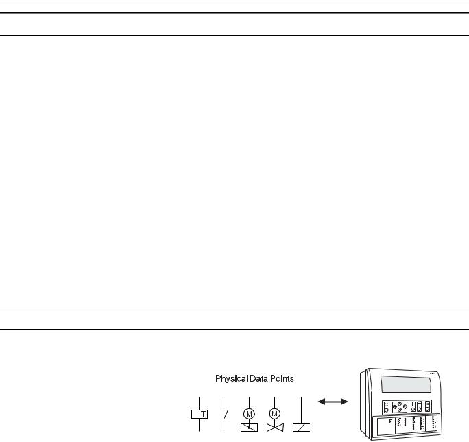
Physical Datapoints
Physical datapoints are inputs and outputs attached to hardware devices like sensors and actuators.
Fig. 3. Physical datapoint symbols
The following are examples of physical datapoints
Analog inputs NTC, PT 1000, PT 3000, BALCO Sensors (PT 3000/BALCO not with Excel 100C), standard 0 (2)...10 V and 0 (4)...20 mA input, to connect e.g. outside air temperature sensors.
Analog outputs Outputs with a continuous 0...10 V output signal for controlling continuous actuators (Excel 100C supplies up to 20 mA on the analog outputs).
Digital inputs Inputs for processing voltage-free signals (switches, contacts).
Digital outputs (not Excel 100C) Outputs for driving three-position actuators, for example, a damper motor; two position devices, for example, a circulation pump; 0...10 V and pulsed outputs
Totalizer inputs Digital inputs for processing pulsed signals up to 20 Hz (depending on Distributed I/O module specifications), for example, metered energy consumption.
EN2B-0092GE51 R0709 |
9 |
DATAPOINTS |
EXCEL 50/100/500/600/800 |
Flexible Datapoints
Flexible datapoints allow the control of more than one physical output with one datapoint. There are three subordinate types of flexible datapoints:
1.Pulse 2
2.Multi-stage
3.Feedback.
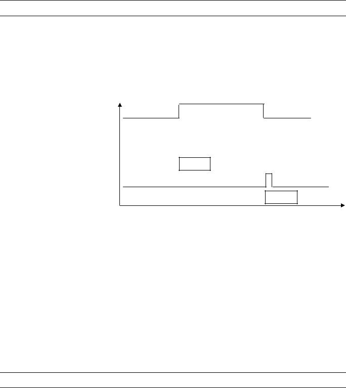
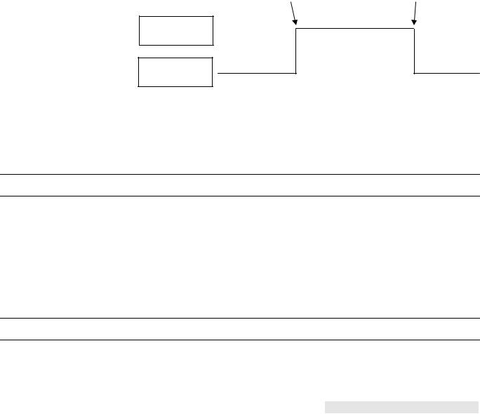
Pulse 2 flexible datapoint A pulse 2 datapoint allows to pulse two digital outputs (e.g. relays). When activated (e.g. set to “on”), Pulse 2 triggers one of the digital outputs, and when deactivated, Pulse 2 triggers the other digital output.
|
|
Pulse 2 “on” |
|
Pulse 2 “off” |
|
|
|
|
|
|
|
|
|
|
|
|
|
|
|
|
|
|
|
Relay 1
Relay 2
Fig. 4. Pulse 2 flexible datapoint switching
Multistage flexible datapoint Multistage flexible datapoints allow to switch up to six physical digital outputs via one datapoint. A typical example would be a multi-stage electric heater or a multistage fan.
A multistage flexible datapoint provides up to six editable stage texts, e.g., stage 1, stage 2, stage 3, etc, to be edited in CARE.
Feedback flexible datapoint Feedback flexible datapoints, also called “DO feedback DI” combine up to three pairs of digital outputs/digital inputs to form up to three-stage switching with feedback. The digital inputs of each pair act as the feedback point.
If the digital input does not feedback the actual equipment status within a predefined time “Off Phase”, then the software will switch down this point type until a "nonalarm" state is reached. In extreme cases, the point may be switched to the off position. See also “Off Phase”.
Increased support (V2.04.xx or higher) Excel 500 controllers now support up to 60 flexible datapoints. In case of Feedback flexible points, the maximum number is 128.
Previous firmware versions supported only up to 20 flexible datapoints.
Pseudo Datapoints
Excel 50/100/500/600 support 256 pseudo datapoints, while Excel 800 supports 381 datapoints (consisting of a random mix of physical and pseudo datapoints)
Pseudo datapoints are values (intermediate results and parameters) computed while the application program is running. In contrast to physical datapoints, pseudo datapoints are not directly connected to hardware devices.
EN2B-0092GE51 R0709 |
10 |
EXCEL 50/100/500/600/800 |
DATA POINTS |
Access via the user address During system operation, you may need to access these values. To simplify this process, you can include pseudo datapoints in the datapoint list, where you can access them directly via their user addresses.
Like physical datapoints, pseudo datapoints, too, can have different attributes; for example, they can specify a manual value, set minimum and maximum values, or log trends.
The following are types of pseudo datapoints:
•Pseudo analog points
•Pseudo digital points
•Pseudo totalizer inputs
•Pseudo point multistage
Pseudo analog points Pseudo analog points are software points containing an analog value in the user program.
A pseudo analog point could, for example, contain a flow temperature setpoint calculated from the room setpoint and the outside air temperature via the heating curve.
Pseudo digital points Pseudo digital points are software points containing a digital value in the user program.
For example, logical AND operation.
The AND operation provides a logical 1 output when all input conditions are also logical 1. Otherwise the output is a logical 0. If the user program contains such an AND operation on different input conditions, then the output could be available as a pseudo digital datapoint.
Pseudo totalizer inputs Pseudo totalizer inputs are digital software points from the user program, where a totalizer counter input is recorded.
Pseudo point multistage Pseudo point multistage datapoints are identical to flexible datapoint of the type "multistage" except that they allow for 16 stages (including the “off stage“) and the attribute "Status Text" allows for 16 status texts to be attached. The attribute "Technical Address" is not required.
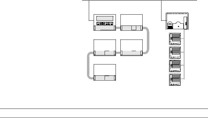
Global Datapoints
If your control and monitoring system contains more than one controller, the controllers communicate with one another via the system bus. Any given controller can thus both receive (read) datapoints from other controllers and transmit datapoints to other controllers. Such datapoints are referred to as global datapoints.
NOTE: The term “global” as used here encompasses more than just those points explicitly labeled as “global” in the CARE engineering tool.
Global datapoints which a controller receives (reads) from other controllers are referred to as local global datapoints, and global datapoints which a controller transmits to other controllers are referred to as remote global datapoints.
During CARE engineering, the program engineer must take care that he does not exceed the maximum allowed 256 global datapoints (remote and local) per controller.
11 |
EN2B-0092GE51 R0709 |
DATAPOINTS |
EXCEL 50/100/500/600/800 |
SYSTEM BUS
C |
LON |
Fig. 5. Global datapoints are available to all controllers on the system bus
Mapped Datapoints (V2.04.xx or higher)
With firmware version V2.04.xx or higher, those Excel 50/500 controllers which feature free programmability on LONWORKS (those that contain the 3120E5 Neuron chip, i.e. date code 0044 or higher) may have I/O devices connected via the LONWORKS network. LONWORKS network variables (or individual fields of structured network variables) can be mapped to the attribute "Value" of physical datapoints (AI/DI/AO/DO). Pseudo analog, pseudo digital, and pseudo multistage points are also supported for NV mapping.
See Excel 50/500 LONWORKS Mechanisms Interface Description, EN0B-0270GE51, for more information on LONWORKS network variables and datapoint mapping.
EN2B-0092GE51 R0709 |
12 |
EXCEL 50/100/500/600/800
ATTRIBUTES
Each datapoint type has associated with it various parameters which allow the user to set, e.g., the user address, the level of access protection, alarm behavior, and other options. These parameters are called attributes. Each attribute performs a specific function related to the datapoint.
A complete list of datapoint types and their attributes appears in Table 17 through Table 19. Not all attributes are available for every datapoint type.
Point refreshing (V1.5.x) Four attributes ("Value", "Manual Value", "Operating Mode", and "Alarm Status") will be simultaneously refreshed to an XL-Online operator interface.
NOTE: A complete list of attributes associated with the various datapoint types can be found in the section "List of Datapoint Attributes" on page 39.
Access Level
Four levels of protection The attribute "Access Level" protects datapoints against unauthorized changes on the basis of the password level needed to modify a datapoint.
"Access Level" attributes between "1" and "4" are assigned to a point. These attributes correspond to the four password levels found in the XI581 (not with XCL5010, Excel 100C), XI582, and XL-Online operator interfaces and the Excel 50 MMI:
•Operator level 1: Read only.
•Operator level 2: Read and make limited changes.
•Operator level 3: Read and make changes.
•Operator level 4: Programming.
For example, setting the "Access Level" attribute for the datapoint with the user address "room temp floor 1" to "2" means that all attributes for this datapoint can now only be edited or modified at password level 2 or higher.
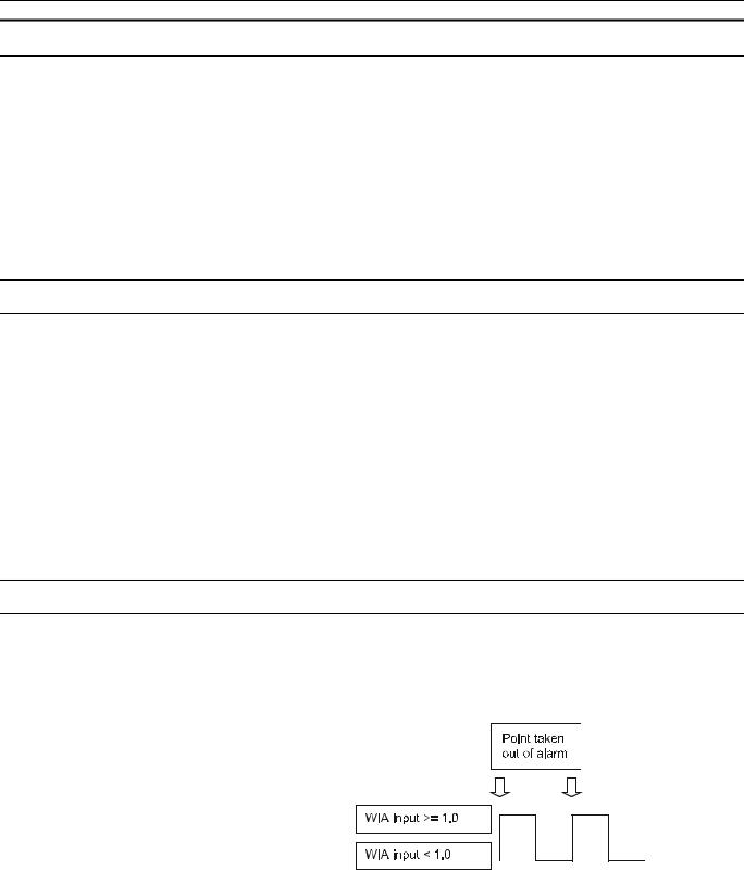
Acknowledge Alarm (V2.04.xx or higher)
The attribute "Acknowledge Alarm" allows a controller to acknowledge an alarm for a flexible datapoint of the type "feedback" without changing the operating mode. The controller takes the point out of alarm as soon as a rising edge is detected on the input of the WIA statement writing to the attribute "Acknowledge Alarm".
Fig. 6. The "Acknowledge Alarm" attribute for WIA statement
This attribute is a virtual attribute and can be accessed only by a WIA statement in CARE. It is not part of the datapoint description and therefore cannot be displayed on an MMI or building supervisor.
EN2B-0092GE51 R0709 |
13 |

ATTRIBUTES |
EXCEL 50/100/500/600/800 |
Active State (prior to V2.04.x)
The attribute "Active State" defines when a digital input/output is active.
NOTE: The "Active State" attribute does not reflect the current condition of a digital datapoint.
NOTE: This is not applicable to digital inputs in applications designed for controllers using V2.04.xx firmware or higher. In such applications, this attribute is fixed at 1, and the new attribute "Normally Open/Normally Closed" (NO/NC) is active (see section "Normally Open/Normally Closed (V2.04.xx or higher)" on page 28 for more details).
The following values are possible:
•0 = digital input/output is active when a "logical 0 signal" is present
•1 = digital input/output is active when a "logical 1 signal" is present
Table 3 indicates the active state for various conditions of the XF523 and XFL523 modules.
Table 3. Active state for the digital input of XF523 and XFL523 modules
|
|
|
|
|
|
|
|
|
digital input |
|
|
|
|
||
|
contact status |
|
|
|
|
open |
|
|
|
closed |
|
||||
|
CARE definition (NC/NO system |
|
|
NC |
|
NO |
|
NC |
|
NO |
|
||||
|
diagram) |
|
|
|
|
|
|
||||||||
|
|
|
|
|
|
|
|
|
|
|
|
|
|
|
|
|
definition - in XL-Online DP-Editor |
|
|
|
|
|
|
|
|
|
|
|
|
|
|
|
attribute "Active State" |
1 |
|
0 |
|
1 |
|
0 |
1 |
|
0 |
1 |
|
0 |
|
|
(change Active/Passive State text) |
|
|
|
|
|
|
|
|
|
|
|
|
|
|
|
CARE interpretation (control table) |
1 |
|
1 |
|
0 |
|
0 |
0 |
|
0 |
1 |
|
1 |
|
|
display at operator interface |
|
OFF/ |
|
ON/ |
|
OFF/ |
|
ON/ |
ON/ |
|
OFF/ |
ON/ |
|
OFF/ |
|
|
trouble: |
operating |
trouble: |
operating |
operating |
|
trouble: |
operating |
|
trouble: |
||||
|
(status text) |
|
|
|
|||||||||||
|
|
alarm |
|
RTN* |
|
alarm |
|
RTN* |
RTN* |
|
alarm |
RTN* |
|
alarm |
|
|
|
|
|
|
|
|
|
||||||||
* RTN = Return To Normal
NOTE: XFL523 Module is applicable only for V2.0.xx software.
Active State (Excel 800)
The attribute "Active State" defines when a digital input/output is active.
1 means, that a digital input/output is active when a "logical 1 signal" is present NOTE: "Active State" = 0 is not allowed/possible.
NOTE: The "Active State" attribute does not reflect the current condition of a digital datapoint.
EN2B-0092GE51 R0709 |
14 |

|
|
EXCEL 50/100/500/600/800 |
|
|
|
|
|
|
|
|
|
ATTRIBUTES |
||
|
|
|
|
Table 4. Active State for the digital input of XF823 and XFL823 modules |
||||||||||
|
|
|
|
|
|
|
|
|
|
|
|
|
|
|
|
|
|
|
|
|
|
|
digital input |
|
|
|
|
||
|
|
contact status |
|
|
open |
|
|
|
closed |
|
||||
|
|
CARE definition (NC/NO system |
NC |
|
NO |
|
NC |
|
NO |
|
||||
|
|
diagram) |
|
|
|
|
||||||||
|
|
|
|
|
|
|
|
|
|
|
|
|
|
|
|
|
definition - in XL-Online DP-Editor |
|
|
|
|
|
|
|
|
|
|
|
|
|
|
attribute "Active State" |
1 |
|
|
1 |
|
|
1 |
|
|
1 |
|
|
|
|
(change Active/Passive State text) |
|
|
|
|
|
|
|
|
|
|
|
|
|
|
CARE interpretation (control table) |
1 |
|
|
0 |
|
|
0 |
|
|
1 |
|
|
|
|
display at operator interface |
OFF/ |
|
|
OFF/ |
|
|
ON/ |
|
|
ON/ |
|
|
|
|
trouble: |
|
|
trouble: |
|
|
operating |
|
|
operating |
|
|
|
|
|
(status text) |
|
|
|
|
|
|
|
|
||||
|
|
alarm |
|
|
alarm |
|
|
RTN* |
|
|
RTN* |
|
|
|
|
|
|
|
|
|
|
|
|
|
|
||||
* RTN = Return To Normal
Alarm Delay
Delaying alarm outputs The alarm delay time (in seconds) is entered in the attribute "Alarm Delay". The alarm delay time determines how long an alarm condition must exist before an alarm is generated. Entering an alarm delay time of 10 seconds means that the limit value must be exceeded for at least 10 seconds before this datapoint generates an alarm. If the limit value lasts for only 7 second, then no alarm occurs.
Alarm Suppression
The attribute “Suppress Alarm” establishes whether or not alarm messages from the following alarm attributes should be suppressed:
•Operational status
•Min/Max. limit
•Maintenance alarm
•Interval counter
•Alarm Status
The following entries are possible:
•Off = Alarms not suppressed
•On = Alarms suppressed
Example: digital input In addition to a variety of other attributes, a digital input also has the "Operating Mode", "Alarm Status", and "Maintenance Alarm" attributes. If alarm suppression is activated for this datapoint, then no message is displayed during an operating mode change-over, or when changing into the alarm condition, or when reaching the maintenance alarm.
Suppression of system |
The controller will not issue a system alarm when the alarm’s system alarm text |
alarms (V2.04.xx or higher) |
starts with an @ character. |
Alarm Status (prior to V2.04.x)
Alarm monitoring In the case of a digital input or a pseudo digital point, the attribute "Alarm Status" specifies whether or not alarm monitoring is required.
The following entries are possible:
• |
Yes |
Alarm monitoring is required |
• |
No |
Alarm monitoring is not required |
15 |
EN2B-0092GE51 R0709 |
ATTRIBUTES |
EXCEL 50/100/500/600/800 |
When alarm monitoring is required, the alarm message occurs when the digital point changes from the active state to the passive state (alarm reached). An additional message is generated (alarm going) when the digital point returns to the active state (see Fig. 7).
Alarm |
|
Alarm |
reached |
|
ending |
|
|
|
DI in
“Active State”
DI in
“Passive State”
Fig. 7. Alarm status messaging
NOTE: The active state and passive state are defined in the "Active State" datapoint attribute.
Alarm Status (V2.04.xx or higher)
Alarm monitoring In the case of a digital input or a pseudo digital point, the attribute "Alarm Status" specifies whether or not alarm monitoring is required.
The following entries are possible:
• |
Yes |
Alarm monitoring is required |
• |
No |
Alarm monitoring is not required |
When alarm monitoring is required, the alarm message occurs depending on the physical contact status and on the logical status as defined in the online attribute “Normally Open/Normally Closed”.
Alarm Type
The attributes listed in Table 5 are capable not only of generating alarms, but also of writing them to the internal alarm memory and sending them to the PC front-end or to the modem module (when connected).
Table 5. Alarm attributes
attribute |
always critical |
optional critical or non-critical |
Operating Mode |
X |
|
Min. Limit |
|
X |
Max. Limit |
|
X |
Maintenance Alarm |
|
X |
Interval Counter |
|
X |
Alarm Status |
|
X |
Changing over the attribute "Operating Mode" always results in a critical alarm, but the attribute "Alarm Type" offers a choice for the alarm attributes "Min. Limit", "Max. Limit", "Maintenance Alarm", "Totalizer", and "Alarm Status" whether an alarm is classified as critical or non-critical.
EN2B-0092GE51 R0709 |
16 |
EXCEL 50/100/500/600/800 |
ATTRIBUTES |
Distinguishing between critical and non-critical alarms is significant for the subsequent reporting of the alarms to the PC front-end or to the modem module. Compared to non-critical alarms, critical alarms are given priority on the bus when several alarms are in the alarm queue.
When the type of alarm for a datapoint has been decided, e.g. "critical" alarm type, it refers to all alarm attributes for this datapoint.
Alarm Definition
In the datapoint description, the alarms can be influenced using the functions described below (see also Table 6 on page 18).
Alarm type For each datapoint in the datapoint description, the user can determine whether the signals generated are to be treated as critical or non-critical alarm.
Alarm delay An alarm signal can be delayed by entering an alarm delay time. An alarm signal will be generated only if an alarm continues uninterrupted during the alarm delay time.
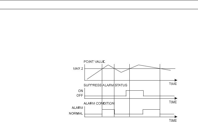
Suppress alarm If an alarm signal is not desired from a particular datapoint, this can be fixed in the datapoint description. Thus, all the alarm signals relevant to the particular datapoint and the "Operating Mode" alarm types are suppressed.
Fig. 8. Alarm condition depending on point value and Suppress Alarm status
Fig. 8 shows an example of a changing point value that rises above and falls below the limit Max 2. If Suppress Alarm is not active, then the alarm condition switches between normal to alarm, according to the limit Max 2. If Suppress Alarm is active, then the alarm condition remains normal unless Suppress Alarm is switched off before the point value falls below the limit Max 2. Regardless of the setting of the Alarm suppression flag, an alarm is entered into the controller's history buffer and is also available in the EBI alarm report.
Point alarm It is possible to view all datapoints at the operator interfaces for which the limit value (analog point) or the alarm status (digital point) is currently exceeded.
Driven by a menu, the user address and the accompanying alarm text are displayed on the XI581 (not with XCL5010, Excel 100C) or XI582 operator interfaces or Excel 50 MMI.
On the XL-Online operator interface, a datapoint within the framework of the datapoint description can be seen in all four password levels. If a current alarm is present for the point in question, the attribute “Point in Alarm” produces the display “Yes”, otherwise “No”.
Within the framework of the datapoint description, it is possible, under the attribute “Alarm text”, to enter an alarm text of up to 18 characters in addition to the preprogrammed text. There are 256 alarm texts in total.
Table 6 presents a summary of various alarm types and attributes.
17 |
EN2B-0092GE51 R0709 |
|
ATTRIBUTES |
|
|
|
|
|
|
|
|
EXCEL 50/100/500/600/800 |
|||
|
|
|
|
|
|
Table 6. Alarm summary |
|
|
|
|
|
||
|
|
|
|
|
|
|
|
|
|
|
|
|
|
|
alarm type/attributes |
|
alarm status |
|
|
enter alarm |
|
alarm |
point in |
no. of prepro- |
|
supplementary |
|
|
|
|
|
delay time |
|
suppression |
alarm |
grammed texts |
|
text |
|
||
|
|
|
|
|
|
|
|
|
|||||
|
Limit Values |
selection in DPD* |
|
possible |
possible |
X |
8 |
possible |
|
||||
|
Alarm Status |
selection in DPD* |
|
possible |
possible |
X |
2 |
possible |
|
||||
|
Maintenance Alarm |
|
selection in DPD* |
|
- |
|
possible |
- |
1 |
- |
|
||
|
Totalizer |
selection in DPD* |
|
- |
possible |
- |
1 |
- |
|
||||
|
Operating Mode |
|
always critical |
|
- |
possible |
- |
2 |
- |
|
|||
|
System Alarms |
always critical |
|
- |
- |
- |
approx. 110 |
- |
|
||||
|
user program reports |
|
always non-critical |
|
- |
- |
- |
- |
- |
|
|||
|
*DPD = datapoint description |
|
|
|
|
|
|
|
|
|
|
||
|
|
|
|
NOTE: A point is still seen as “in alarm” even when alarm suppression is enabled. |
|||||||||
Cycle Count
The attribute "Cycle Count" contains the value indicating the number of transitions to the active state (see "Active State (prior to V2.04.x)" on page 14).
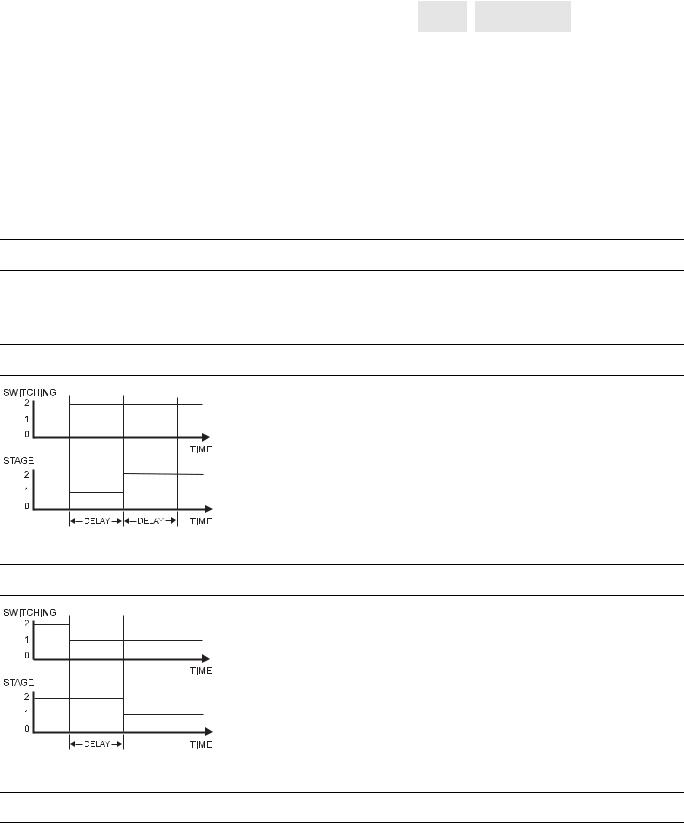
Delay Time Switching Up
This attribute is used in conjunction with flexible points of the type "feedback". It defines the delay time between
switching upwards from one stage to another. The delay
time affects every stage. The delay time also takes effect
when switching, e.g. from manual value 0 to 2. In this case,
it is switched from stage 0 to stage 1, then to stage 2 with
the delay time between the switching processes.
•
•
•
Fig. 9. Delay time switching up
Delay Time Switching Down
This attribute is used in conjunction with flexible points of the type "feedback". It defines the delay time between switching downwards from one stage to another. The delay time affects every stage.
• Range: 0 to 255s
• Default value: 10s
• Resolution: 1s
The feedback delay time starts to count after termination of delay time switching up/delay time switching down.
Fig. 10. Delay time switching down
Descriptors
Informative descriptors A controller contains up to 128 physical datapoints and up to 256 pseudo datapoints. The Excel 100C provides 36 physical datapoints. An individual user address can be assigned to each of these 384 datapoints.
EN2B-0092GE51 R0709 |
18 |

EXCEL 50/100/500/600/800 |
ATTRIBUTES |
255 plain-language descriptors can be created with a maximum of 32 characters each. These descriptors are then assigned to datapoints in the datapoint description via the attribute "Descriptor".
Descriptors complete the information concealed behind the user address. They can contain, for instance, a reference to a section of a building.
The following list is an example of the relationship between user addresses and descriptors:
User Address |
Descriptor |
Room temp floor 1 |
Heating circuit, West wing |
Room temp floor 3 |
Heating circuit, West wing |
Room temp floor 10 |
Heating circuit, East |
Room temp corridor |
Heating circuit, East |
Flow temp floor 1 |
Heating circuit, West wing |
Lights floor 1 |
Building section V |
Lights corridor |
Building section V |
Engineering Unit
The attribute "Engineering Unit" contains a list for selecting different engineering units for both analog datapoints (physical and pseudo), totalizer inputs (physical and pseudo), and digital datapoints.
If, for instance, the external temperature is measured by an analog datapoint, the engineering unit of this datapoint must be set to "°C" or "°F". If the electrical load is detected by a totalizer input, the engineering unit must be set to "kWh" for kilowatthours.
Feedback Delay
The attribute "Feedback Delay" determines the time delay between, e.g. when a pump switched on (and detected) and when this status is made available to a program.
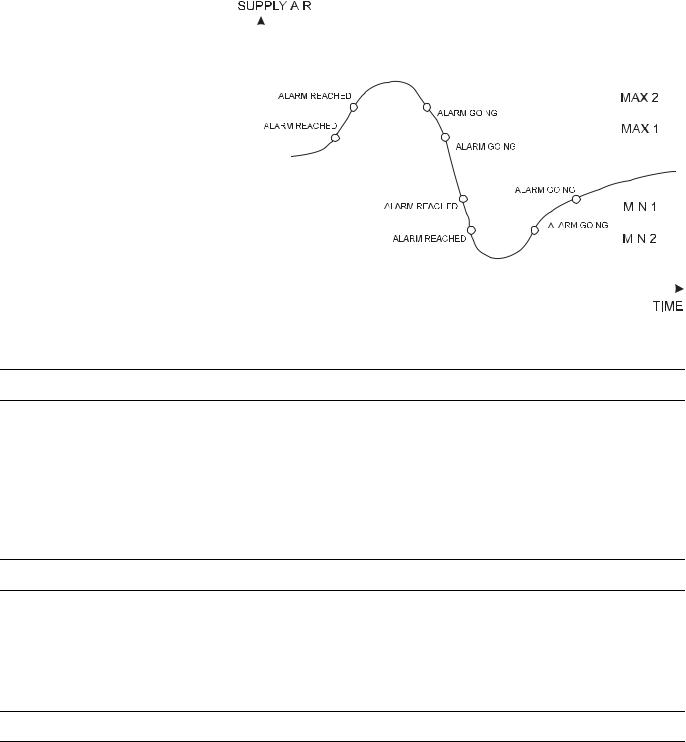
High/Low Alarm/Warning Limits
Specifying limit values In the case of analog inputs (e.g. inputs for sensing room temperature) and pseudo analog points (for instance, internally computed datapoints for the heating flow setpoint), two minimum and two maximum monitored limit values may be entered.
The following four limit value attributes exist:
•Low Warning Limit
•Low Alarm Limit
•High Warning Limit
•High Alarm Limit
Exceeding the limit values generates an alarm.
Example: Monitoring supply air temperature limits (see Fig. 11).
19 |
EN2B-0092GE51 R0709 |
ATTRIBUTES |
|
|
|
|
EXCEL 50/100/500/600/800 |
|||||
|
|
|
|
|
|
|
|
|
|
|
|
|
|
|
|
|
|
|
|
|
|
|
|
|
|
|
|
|
|
|
|
|
|
|
|
|
|
|
|
|
|
|
|
|
|
|
|
|
|
|
|
|
|
|
|
|
|
|
|
|
|
|
|
|
|
|
|
|
|
|
|
|
|
|
|
|
|
|
|
|
|
|
|
|
|
|
|
|
|
|
|
|
|
|
|
|
|
|
|
|
|
|
|
|
|
|
|
|
|
|
|
|
|
|
|
|
|
|
|
|
|
|
|
|
|
|
|
|
|
|
|
|
|
|
|
|
|
|
|
|
|
|
|
|
|
|
|
|
|
|
|
|
|
|
|
|
|
|
|
|
|
|
|
|
|
|
|
|
|
|
|
|
|
|
|
|
|
|
|
|
|
|
|
|
|
|
|
|
|
|
|
|
|
|
|
|
|
|
|
|
|
|
|
|
|
|
|
|
Fig. 11. Monitoring supply air temperature limits
Hours Run
Display of elapsed hours The attribute "Hours Run" returns the total number of hours during which any of the stages is in the ON position. However, if more than one stage is in the ON position, the "Hours Run" count is not added up, but rather counted only once.
Display of the elapsed hours run with activated hours run logging (see also "Hours Run Log" on page 20).
NOTE: If the attribute "Active State" of the point is 0, then the OFF position is also counted.
Hours Run Log
Hours run log An hours run log can be carried out for digital datapoints (physical and pseudo) and for flexible datapoints, e.g. logging the hours run by a heating circuit pump. This requires the decision: hours run log = Yes/No to be made in the attribute "Hours Run Log". The accumulated hours run are displayed in the attribute “Hours Run”. Hours run are logged with a sample rate of 1 minute.
Hours Since Serviced
Display hours run since last maintenance The elapsed hours run since the last maintenance work are totaled in the attribute "Last Maintained". If, for example, the maintenance alarm is 500 hours, and a pump has already been running for 120 hours, then the entry in the attribute “Last maintained” will be 120 hours. By comparing the attributes "Maintenance Alarm" and "Last Maintained", the user can see that the next maintenance period will be after an additional 380 hours have elapsed.
If the maintenance alarm is reached, and the maintenance work has been performed, the counter can be reset manually. The counter can also be reset manually before reaching the maintenance alarm if, for instance, the maintenance has been performed earlier.
EN2B-0092GE51 R0709 |
20 |
Loading...