


 Loading...
HE240, HE280
Humidifier and
Installation Kit
INSTALLATION GUIDE/OWNER’S MANUAL
M33322
SAVE THIS DOCUMENT
FOR FUTURE REFERENCE
69-2685ES-01

HE240, HE280 HUMIDIFIER AND INSTALLATION KIT
Safety Definitions
These safety terms identify information you must read prior to installing or operating the humidifier.
WARNING
Indicates a hazardous situation which, if not avoided, could result in death or serious injury.
CAUTION
Indicates a hazardous situation which, if not avoided, could cause bodily injury or property damage.
Safety Precautions
Make sure you read and understand the following safety hazards before installing, using, or working with the humidifier:
WARNING
Serious Personal Injury Hazard.
Can cause electrical shock and injury from moving parts.
Disconnect power and shut off water supply before removing cover.
WARNING
Hazardous Voltage
Can cause personal injury or equipment damage.
Do not cut or drill into any air conditioning or electrical accessory.
CAUTION
Chemical Hazard.
Can cause personal injury or equipment damage.
Do not use any line connected to an air conditioner.
Do not use gas line.
CAUTION
Temperature and Static Pressure Hazard. Can cause property or equipment damage.
Locate humidifier where ambient temperature is between 32 and 120 °F (0 to 49 °C). Do not install humidifier where freezing temperatures could occur.
Be sure supply plenum static pressure is no greater than 0.4 in. wc and water pressure is no greater than 120 psi.
CAUTION
Sharp Edges Installation Hazard.
Can cause personal injury.
Wear gloves and safety glasses.
69-2685ES—01 |
2 |
HE240, HE280 HUMIDIFIER AND INSTALLATION KIT
IMPORTANT
Read and save these instructions.
WELCOME
Congratulations on your purchase of a Honeywell whole-house humidifier. Proper use of a Honeywell humidifier has numerous benefits related to your family’s health and comfort, as well as helping to safeguard and protect your home.
How Your Humidifier Works
Your Honeywell humidifier uses the principle that vapor (evaporated water) is created when warm air blows over a water-soaked area. As the vapor circulates, the relative humidity rises.
Your humidity control monitors the relative humidity and activates the humidifier accordingly. The humidifier has a water supply that dispenses water evenly over a humidifier pad. The warm dry air from the furnace passes over the humidifier pad and picks up the moist air to circulate it throughout your home.
Humidified air feels warmer and more comfortable so you may be able to lower your thermostat heating setpoint, which saves money on your heating fuel bills. The end result is that your humidifier gives you a comfortable environment that is also energy efficient.
Model Specific Features
The HE280 humidifier has water savings technology built in that could save up to 30% versus leading brands. This translates to up to 20 gallons of water saved per day!
APPLICATION
This kit contains your new Honeywell HE240 or HE280 Humidifier, H8908 Humidistat and all the accessories required for installation.
3 |
69-2685ES—01 |
HE240, HE280 HUMIDIFIER AND INSTALLATION KIT
PREPARING FOR THE INSTALLATION
Be sure to identify all the required (Table 1) accessories (included) and make sure the appropriate tools are available before beginning the installation.
Included Accessories
Table 1. Included Accessories.
Quantity |
Accessory |
|
48 in. (1.22 m) |
Bypass ducting including: |
|
6 in. (155 mm) diameter flexible duct |
||
|
||
|
|
|
20 ft (6.2 m) |
18 gauge, two-strand thermostat wire |
|
|
|
|
20 ft (6.2 m) |
1/4 in. (6.35 mm) OD feed water tubing |
|
|
|
|
10 ft (3.1 m) |
1/2 in. (12.7 mm) ID drain tubing |
|
|
|
|
|
Connecting and mounting hardware: |
|
1 bag |
4 mounting screws |
|
|
1 drain tube clamp |
|
|
|
|
1 |
H8908 Humidistat |
|
|
|
|
|
Saddle Valve Assembly: |
|
|
1 saddle valve and top clamp |
|
|
1 threaded bottom clamp |
|
1 bag |
2 bolts |
|
1 rubber gasket |
||
|
||
|
1 brass insert |
|
|
1 plastic bushing |
|
|
1 eyelet |
|
|
|
|
1 |
Plug-in transformer |
|
|
|
|
1 |
Foil tape roll |
|
|
|
|
|
1 plastic elbow |
|
|
1 grommet |
|
1 bag |
1 connector strap |
|
|
1 PVC tubing |
|
|
1 wire nut |
|
|
|
|
1 |
Mounting template |
|
|
|
Required Tools
Tools required for installation include:
•Tin snip
•Screwdriver
•Pliers
•Adjustable or open-end wrench
•Drill
•Level
•3/4 in. (19 mm) sheet metal drill bit
69-2685ES—01 |
4 |
HE240, HE280 HUMIDIFIER AND INSTALLATION KIT
Determining Best Location for Humidifier
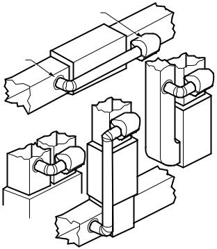
•Select a location for the humidifier on the supply (warm air stream) duct. See Fig. 1 for examples. Return duct mounting is acceptable if there are space restrictions on the supply duct. If you are mounting the humidifier on the return duct, simply swap “return duct” for “supply duct” throughout these instructions.
•Select a location that cannot damage the air conditioner A-coil during installation.
•Do not locate the humidifier on the furnace body.
•Mount the humidifier in a conditioned space to prevent freezing.
•Mount the humidifier at least 3 in. (78 mm) above the furnace body to allow adequate space for the solenoid valve and drain line.
HUMIDIFIER
BYPASS COLLAR
HORIZONTAL
HIGHBOY
DOWN
FLO
LOWBOY
M12248D
Fig. 1. Typical humidifier installation locations.
5 |
69-2685ES—01 |
HE240, HE280 HUMIDIFIER AND INSTALLATION KIT
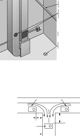
CHOOSE A LOCATION IN A CONDITIONED
SPACE THAT HAS ACCESS TO A WATER SUPPLY
PIPE. COLD OR HOT WATER CAN BE USED.
SELECT A SURFACE ON THE HVAC SUPPLY OR
RETURN DUCT WITH CLEARANCE FOR THE
SOLENOID VALVE, DRAIN LINE AND COVER
REMOVAL.
 LOCATION MUST ALSO HAVE ACCESS TO 120
VAC POWER.
ENSURE THE LOCATION IS NEAR A DRAIN.
CONSULT LOCAL PLUMBING CODES FOR
PROPER DRAINAGE.
M33410
Fig. 2. Typical humidifier installation locations.
Selecting Location for Humidistat
•Select a location for the humidistat on the return plenum or on the wall in the living space.
•Mounting on the return plenum is the easiest installation for the control wiring circuit.
IMPORTANT
The humidistat must be mounted upstream from the humidifier or bypass duct to ensure it is properly sensing the relative humidity of the living space. Locate the control at least 8 in. (203 mm) upstream from the humidifier in the return air duct. (See Fig. 3.)
|
ALTERNATE LOCATION |
RETURN |
RETURN |
AIR |
AIR |
6 in. (152 mm)
MINIMUM
 15 in. (381 mm) MINIMUM
BEST
LOCATION
RETURN AIR DUCT 
M12831
Fig. 3. Selecting duct location for humidistat.
Locating Closest 120 V Electrical Outlet
•Select location with access to an outlet. If not available, contact an electrician to have one installed.
•Make sure that the 20 ft (6.2 m) of thermostat wire is adequate to reach from the humidifier to the humidistat, and also from the humidifier to the transformer. Please note that the thermostat wire will need to be cut into the 2 correct lengths. See “Wiring” on page 14 for more information.
69-2685ES—01 |
6 |

HE240, HE280 HUMIDIFIER AND INSTALLATION KIT
INSTALLATION
1.Turn off power to the air handling system at the circuit breaker.
2.Draw a level line on the plenum in the selected location.
IMPORTANT
To ensure optimal product performance, be sure the mounting template is level before marking. Use of a small level is recommended.
3.Locate the template (form number 69-2710 included in the box). For the HE240 model, cut out the template along the dotted line.
4.Tape the template in position and trace around the template.
5.Remove the template and carefully cut the rectangular opening using tin snips.
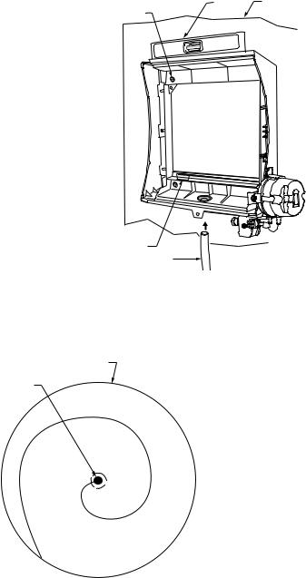
6.Disassemble the humidifier; remove the cover and take out the humidifier pad assembly. See Fig. 4.
COVER 
SIDEWALL 
BY-PASS SIDEWALL 
WATER
FEED NOZZLE
PerfectFLO™ WATER
DISTRIBUTION TRAY


HUMIDIFIER
PAD ASSEMBLY 
FRAME 
HUMIDIFIER
HOUSING 
WATER
FEED TUBE
SOLENOID VALVE


PRESSURE SWITCH
M33323
Fig. 4. Disassembling humidifier.
7 |
69-2685ES—01 |
HE240, HE280 HUMIDIFIER AND INSTALLATION KIT
7.Make sure the humidifier housing is level, then position it in the opening so the plastic tabs are in place on the lower sheet metal edge of the opening. Use pliers, as necessary, to flatten cut edges. See Fig. 5.
8.Secure the humidifier housing to the opening at the top and bottom using sheet metal screws.
9.Use the 6 in. (155 mm) starter collar as a template to mark the opening for the bypass. The starter collar end can be identified by the pliable metal tabs.
SHEET METAL |
LEVEL |
DUCT |
|
|
|
SCREWS (4) |
|
|
OPENING
TOAIR DUCT
PLASTIC
TABS (2)
DRAIN TUBING |
M33324 |
Fig. 5. Installing humidifier on duct.
10.Carefully cut the opening for the 6 in. (155 mm) starter collar end of the 48 in. (1.22 m) flex duct. See Fig. 6. Use a drill to start the cut in the middle of the circle. Cut in an outward spiral to assist in controlling the cut.
6 IN. ROUND TEMPLATE
STARTING
HOLE
M20172
Fig. 6. Cutting bypass opening.
69-2685ES—01 |
8 |
HE240, HE280 HUMIDIFIER AND INSTALLATION KIT
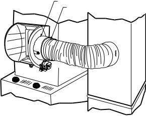
11.Reassemble humidifier side plates to customize the orientation for your specific install. The side plate with the humidifier port needs to be on the side of the humidifier that is closest to the 6 in. (155mm) hole cut in Step 10.
12.Insert flex duct with starter collar into the 6" (155mm) hole that was cut in Step 10. Reach into hole THROUGH THE FLEX DUCT so that the pliable metal tabs can be bent outwards into the hole. These tabs, when bent outwards, will help secure the flex duct into your home's duct work.
13.Slide remaining loose end of flex duct over the humidifier port on the HE240/ HE280, making sure that the flex duct advances past the raised plastic tabs on the port. These tabs will help to hold the flex duct in place. Verify that the damper blade has adequate clearance to move back and forth between the summer and winter positions. Secure the flex duct in place with the plastic connector strap.
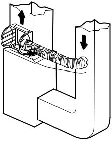
14.Seal the duct connec-
tions with foil tape. Seal both
1)the connection between the starter collar end of the flex duct and the home's duct work and
2)the end of the flex duct to the humidifier over the top of the connector strap.
15.Reinstall the humidifier pad assembly in the humidifier housing.
16.Hinge the cover in place and secure with the thumbscrew located at the bottom of the cover.
HUMIDIFIER PORT
CONNECTOR STRAP
M33325
Fig. 7. Connecting bypass ducting.
9 |
69-2685ES—01 |

HE240, HE280 HUMIDIFIER AND INSTALLATION KIT
Connecting the Plumbing
Use hot or cold water and either hard or softened water in the humidifier.
NOTE: Using hot water will increase operating costs, but may provide a small increase in the amount of humidity delivered.
IMPORTANT
Please consult local plumbing code for proper plumbing regulations before beginning. Use of a manual shutoff valve may be required to meet code in your area.
1.Shut off the water.
2.Use the self-piercing saddle valve (included) to tap into the water supply line at the location selected. Turn the handle on the top of the saddle valve to the right (clockwise) until the needle pierces the water supply line. Leave the needle in this position until the humidifier is fully installed to prevent leaking (even though the water supply is turned off, there can still be water in the line that will leak as soon as the needle is backed out). See Fig. 8. If tapping into galvanized pipe, drain the line and pre-drill 3/16 in. tap for the saddle valve.
 SCREW DRIVER
WATER LINE
M20175
Fig. 8. Installing the saddle valve.
NOTE: The saddle valve is not designed to regulate water flow. The valve is either open or closed.
IMPORTANT
To prevent debris from clogging the solenoid in-line filter, be sure to install the saddle valve handle pointing toward the ceiling.
3.Use 1/4 in. (6 mm) OD tubing and connect the saddle valve to the inlet side of the solenoid valve on the humidifier (see Fig. 9).
a.Place the brass compression nut over the tubing.
b.Slide the plastic compression ring over the tubing. (Discard copper compression ring provided with valve.)
c.Install brass insert into end of tubing.
BRASS COMPRESSION NUT
PLASTIC
COMPRESSION
RING
BRASS INSERT
M33404
Fig. 9. Installing feed tubing.
NOTE: To prevent leaking, use plastic (Delrin) compression rings with plastic tubing. Use copper sleeve rings only with copper tubing.
69-2685ES—01 |
10 |
HE240, HE280 HUMIDIFIER AND INSTALLATION KIT
d.Insert the tubing into the saddle valve fitting and support the valve while tightening the compression nut.
e.Insert plastic supply tubing into quick connect fitting. Insert fully, and apply modest pull pressure to ensure a tight fit.
4.Use the following steps to install a 1/2 in. (13 mm) drain tube between the
humidifier and the floor drain (see Fig. 10).
a. Slide the drain clamp over the tubing.
b. Push the tubing over the drain nipple on the humidifier.
c. Hand-tighten the clamp around the
tubing to secure it to the humidifier drain. The clamp is tightened by compressing the two sides together so that one side fits into the ridged grove on the other side.
d. Secure the tubing (can use foil tape) along the route to prevent movement
and ensure downward slope for cor-
rect drainage.
M20177
Fig. 10. Installing the drain tubing. NOTE: Cut tubing to correct length so the tubing terminates at the drain.
Connecting the Pressure Switch
1. If the humidifier is installed on the supply duct (as is recom-
mended), the pressure switch needs to have the tubing fed to
the return duct. If the humidifier is installed on the return duct,
the pressure switch needs to
have the tubing fed to the supply duct.
2. Drill a 3/4-in. (19 mm) diameter hole in the duct within 10 ft.
(3 m) of the switch to ensure the provided tubing reaches the pressure tap elbow.
M33405
Fig. 11. Pressure switch.
11 |
69-2685ES—01 |
HE240, HE280 HUMIDIFIER AND INSTALLATION KIT
3.Insert the black rubber grommet into the duct hole.
4.Connect the tubing to the tubing fitting elbow and insert the tubing fitting elbow into the black rubber grommet.
5.Connect the other end of the tubing to the applicable pressure connection on the switch.
a.If the humidifier is installed on the supply duct (as is recommended), the tube that inserts into the humidifier needs to be attached to the black port, and the tube that runs to the return duct needs to be attached to the gray port.
b.If the humidifier is installed on the return duct, the tube that inserts into the humidifier needs to be attached to the gray port, and the tube that runs to the supply duct needs to be attached to the black port.
M33326
Fig. 12. Installing the pressure switch tubing.
6.You may cut the tubing to fit the connection length between the elbow fitting and switch. It is also recommended to secure the hose to existing structures to avoid accidental disconnection.
69-2685ES—01 |
12 |
Loading...