


FR124
FR124
Einbauanleitung • Installation instructions • Notice de montage • Installatiehandleiding • Istruzioni di montaggio
Instrucciones de montaje • Asennusohje • Installasjoninstruksjon • Monteringsanvisning • Инструкция по монтажу
Instrukcja montażu • Návod na montáž • Beépítési útmutató • Montaj kılavuzu • Instrucţiuni de montaj • Montážny návod
Інструкція з монтажу
Anleitung zum späteren Gebrauch aufbewahren!
Keep instructions for later use!
Conserver la notice pour usage ultérieur!
Handleiding bewaren voor later gebruik!
Conservare le istruzioni per uso successivo!
Guardar estas Instrucciones para su uso futuro!
Säilytä ohje vastaisen varalle!
Ta vare på bruksanvisningen for senere bruk!
Förvara bruksanvisningen för senare användning!
Сохранить инструкцию для последующего
пользования!
Zachowa instrukcj do pózniejszego wykorzystania!
Návod uschovejte pro pozdější použití!
Az útmutatót őrizze meg a későbbi használatra!
K1lavuzu ileride kullanmak üzere saklay1n!
Pstraci instrucciunile pentru o utilizare ulterioar!
Návod uchovajte pre neskoršie použitie!
Зберігати інструкцію для подальшого
використання!
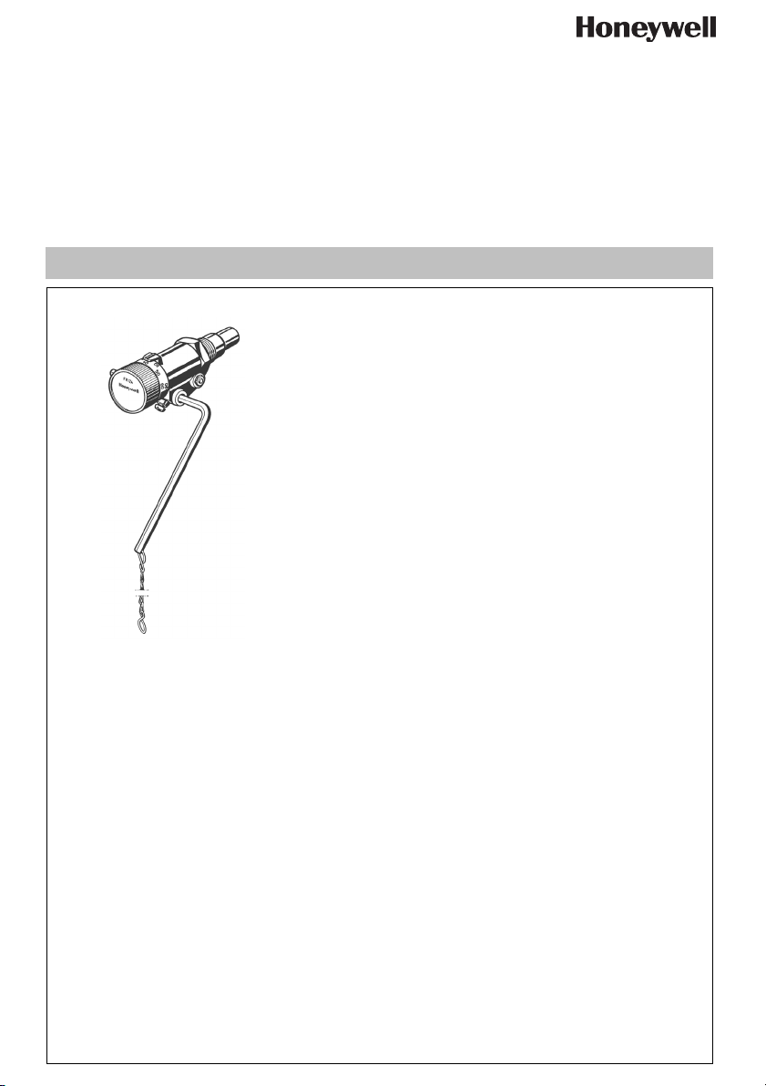
Feuerungsregler
Combustion regulator
Régulateur de combustion
Stookregelaar
Regolatore del bruciatore
Regulador de combustión
Paloilman säädin
Forbrenningsregulator
Eldningsregulator
Регулятор горения
Regulator paleniska
Regulátor spalování
Tüzelésszabályozó
Ateşleme regülatörü
Regulator de aprindere
Regulátor spaľovania
Регулятор спалювання
EB-FR124 Rev. A

MU1H-1515GE23 R0709 2 Honeywell GmbH
D
1. Sicherheitshinweise
1. Beachten Sie die Einbauanleitung.
2. Benutzen Sie das Gerät
• bestimmungsgemäß
• in einwandfreiem Zustand
• sicherheits- und gefahrenbewusst.
3. Beachten Sie, dass das Gerät ausschließlich für
den in dieser Einbauanleitung genannten Verwen-
dungsbereich bestimmt ist. Eine andere oder
darüber hinausgehende Benutzung gilt als nicht
bestimmungsgemäß.
4. Beachten Sie, dass alle Montage-, Inbetriebnahme,
Wartungs- und Justagearbeiten nur durch autori-
sierte Fachkräfte ausgeführt werden dürfen.
5. Lassen Sie Störungen, welche die Sicherheit beein-
trächtigen können, sofort beseitigen.
2. Funktionsbeschreibung
Der Feuerungsregler dient dazu, die Luftzufuhr für die
Verbrennung zu regeln. Der eingebaute Thermostat
misst die Temperatur im Wärmeerzeuger und regelt in
Abhängigkeit davon über einen Hebel mit Kette die
Luftzufuhr des feststoffbeheizten Heizkessels durch
Öffnen bzw. Schließen der Luftklappe.
3. Verwendung
Für Heizungsanlagen nach DIN 4751 mit Feststoff-
und Wechselbrandkesseln
Der Feuerungsregler FR124 darf insbesondere in
folgenden Fällen nicht verwendet werden:
• Explosionsgefährdete Umgebung
Bei Betrieb in explosionsgefährdeten Bereichen
kann Funkenbildung zu Verpuffungen, Brand oder
Explosionen führen.
4. Technische Daten
5. Lieferumfang
Der Feuerungsregler besteht aus:
• Gehäuse
• Einstellknopf
• Tauchhülse
• Hebelstange
• Kette
• Dehnstoff-Thermostat
• Rückstellfeder
6. Varianten
7. Montage
7.1 Einbauhinweise
• Einbaulage horizontal oder vertikal
• Feuerungsregler im Wasserkreislauf des Kessels
einbauen
• Nur in die dafür vorgesehene Gewindemuffe
einbauen
7.2 Montageanleitung
1. Gewinde mit einem Hanf- oder Teflonband
abdichten.
2. Tauchrohr (Gewinde G
3
/
4
) in die Gewindemuffe des
Kessels einschrauben
3. Hebelstange fixieren
4. Kette an der Hebelstange und der Zuluftklappe
befestigen
o Die Kette hängt frei und die Hebelstange bewegt
sich beim Drehen des Einstellknopfs frei
8. Inbetriebnahme
8.1 Feuerungsregler kalibrieren
1. Kessel bei manuell geöffneter Zuluftklappe
anheizen
2. Einstellknopf des Feuerungsreglers auf „60“
einstellen
3. Wenn die Wassertemperatur 60 °C erreicht hat und
stabil bleibt, die Länge der Kette so anpassen, dass
die Tür 2 mm offen bleibt.
Sollwertbereich 30...90 °C
zulässige Fühlertemperaturmax. 115 °C
Umgebungstemperatur max. 70 °C am Schaltkopf
Anschlussgröße G 3/4"
Kettenlänge 1,2 m
Kettenbelastung 100...600 g
Tauchrohrlänge 53 mm
FR124-3/4A = Normalausführung

Honeywell GmbH 3 MU1H-1515GE23 R0709
D
9. Störungen / Fehlersuche
10. Entsorgung
• Gehäuse und Einstellknopf aus hochwertigem
Kunststoff
• Tauchhülse aus Messing
• Hebelstange aus Stahl, verzinkt
• Kette aus Stahl, verzinkt
Störung Ursache Behebung
Temperatur liegt im stabilisierten
Betriebszustand unter dem einge-
stellten Wert.
Zu wenig Luftzufuhr Kette verkürzen
Weitere Einflüsse, z. B. zu viel Asche
im Kessel.
Unabhängig vom FR124 alle
weiteren Einflüsse überprüfen, z. B.
Brennstoff- und Aschenmenge, Lage
der Beiluftklappe, Trägheit des
Kessels und des gesamten
Heizungssystems
Temperatur liegt im stabilisierten
Betriebszustand über dem einge-
stellten Wert.
Zu viel Luftzufuhr Kette verlängern
Zuluftklappe klemmt und geht nicht
zu
Zuluftklappe ölen
Weitere Einflüsse, z. B. zu viel Asche
im Kessel.
Unabhängig vom FR124 alle
weiteren Einflüsse überprüfen, z. B.
Brennstoff- und Aschenmenge, Lage
der Beiluftklappe, Trägheit des
Kessels und des gesamten
Heizungssystems
Sonstige Störungen Technische Kundenberatung
anrufen

MU1H-1515GE23 R0709 4 Honeywell GmbH
GB
1. Safety Guidelines
1. Follow the installation instructions.
2. Use the appliance
• according to its intended use
• in good condition
• with due regard to safety and risk of danger.
3. Note that the appliance is exclusively for use in the
applications detailed in these installation instruc-
tions. Any other use will not be considered to comply
with requirements and would invalidate the
warranty.
4. Please take note that any assembly, commis-
sioning, servicing and adjustment work may only be
carried out by authorized persons.
5. Immediately rectify any malfunctions which may
influence safety.
2. Functional description
The Combustion Regulator controls combustion by
adjusting the supply of air to a boiler. The intergral ther-
mostat measures the temperature in the heat gene-
rator and in relationship to the temperature regulates a
lever with chain linkage to control the air inlet to the
solid fuel boiler by opening or closing the air flap.
3. Application
For solid fuel and multi-fuel heating installations to DIN
4751
The FR124 Combustion Regulator may in particular
not be used in the following cases:
• Explosive environments. Sparks can lead to defla-
gration, fire or explosions during operating in explo-
sive areas.
4. Technical data
5. Scope of delivery
The FR124 Combustion Regulator consists of:
• Housing
• Adjuster knob
• Immersion pocket
• Lever rod
• Chain
• Wax thermostat
• Return spring
6. Options
7. Assembly
7.1 Installations Guidelines
• Horizontal or vertical installation
• Install Combustion Regulator in the water cycle of
the boiler
• Only install it in the screw socket intended for this
purpose
7.2 Assembly instructions
1. Seal threaded joint with hemp or Teflon tape.
2. Screw immersion tube (thread T
3
/
4
) into the
threaded socket of the boiler
3. Secure the lever rod
4. Secure chain to the lever rod and the inlet air flap
o The chain hangs free and the lever rod moves
freely when the adjuster knob is turned
8. Commissioning
8.1 Calibrating the Combustion Regulator
1. Heat up the boiler with manually opened inlet air flap
2. Set the adjuster knob on the Combustion Regulator
to "60"
3. Once the water temperature has reached and main-
tained 60 °C adjust the chain length so that door 2
remains open.
Setting range 30...90 °C
Permissible sensor
temperature
max. 115 °C
Ambient air temperature max. 70 °C on adjuster
knob
Connection size T 3/4"
Chain length 1.2 m
Chain load 100...600 g
Immersion tube length 53 mm
FR124-3/4A = Standard version
Honeywell GmbH 5 MU1H-1515GE23 R0709
GB
9. Troubleshooting
10. Disposal
• High-quality synthetic material housing and adjuster
knob
• Brass sensor pocket
• Galvanized steel lever rod
• Galvanized steel chain
Problem Cause Remedy
Temperature during stabilised opera-
tion is below the set value.
Too little inlet air Shorten chain
Other influences, e.g. too much ash
in the boiler.
Irrespective of the FR124, check all
other influences, e.g. fuel and ash
quantities, position of the admixed air
flap, boiler inertia and the entire
heating system
Temperature during stabilised opera-
tion is above the set value.
Too much inlet air Extend chain
Inlet air flap is jammed and does not
shut
Oil inlet air flap
Other influences, e.g. too much ash
in the boiler.
Irrespective of the FR124, check all
other influences, e.g. fuel and ash
quantities, position of the admixed air
flap, boiler inertia and the entire
heating system
Other faults Call Technical Customer Service

MU1H-1515GE23 R0709 6 Honeywell GmbH
F
1. Consignes de sécurité
1. Suivre les indications de la notice de montage.
2. En ce qui concerne l'utilisation de l'appareil
• Utiliser cet appareil conformément aux données du
constructeur
• Maintenir l'appareil en parfait état
• Respectez les consignes de sécurité
3. Il faut noter que cet équipement ne peut être mis en
oeuvre que pour les conditions d'utilisation menti-
onnées dans cette notice. Toute autre utilisation, ou
le non respect des conditions normales d'utilisation,
serait considérée comme non conforme.
4. Observer que tous les travaux de montage, de mise
en service, d'entretien et de réglage ne pourront
être effectués que par des spécialistes autorisés.
5. Prendre des mesures immédiates en cas d'anoma-
lies mettant en cause la sécurité.
2. Description fonctionnelle
Le régulateur de combustion sert à réguler l'alimenta-
tion d'air pour la combustion. Le thermostat intégré
mesure la température dans le générateur de chaleur
et régule en conséquence via un levier avec une
chaîne l'alimentation d'air de la chaudière chauffée
avec le combustible solide en ouvrant ou en fermant le
clapet d'air.
3. Mise en oeuvre
Pour installations de chauffage selon DIN 4751 avec
chaudières à combustible solide et chaudières mixtes
Le régulateur de combustion FR124 ne doit pas être
utilisé en particulier dans les cas suivants:
• Environnements à risques d'explosion En cas
d'exploitation dans des environnements à risques
d'explosion, la production d'étincelles peut conduire
à des déflagrations, un incendie ou des explosions.
4. Caractéristiques
5. Contenu de la livraison
Le régulateur de combustion est composé de:
• Boîtier
• Bouton de réglage
• Doigt de gant
• Barre de levier
• Chaîne
• Thermostat à matière dilatable
• Ressort de rappel
6. Variantes
7. Montage
7.1 Dispositions à prendre
• Position de montage horizontale ou verticale
• Monter le régulateur de combustion dans le circuit
d'eau de la chaudière
• Montage uniquement dans le manchon fileté prévu
à cet effet
7.2 Instructions de montage
1. Étanchéifier le filetage avec une bande de chanvre
ou de téflon.
2. Visser le tube plongeur (Filetage G
3
/
4
) dans le
manchon fileté de la chaudière
3. Fixer la barre de levier
4. Fixer la chaîne à la barre du levier et au clapet
d'alimentation d'air
o La chaîne pend librement et la barre de levier
bouge librement quand on tourne le bouton de
réglage
8. Mise en service
8.1 Calibrer le régulateur de combustion
1. Allumer la chaudière, le clapet d'alimentation d'air
étant ouvert manuellement
2. Régler le bouton de réglage du régulateur de
combustion sur „60“
3. Quand la température de l'eau a atteint 60°C et est
stabilisée, ajuster la longueur de la chaîne de sorte
que la porte reste ouverte de 2 mm.
Plage de valeurs nomi-
nales
30...90 °C
Température de sonde
admise
max. 115 °C
Température ambiante max. 70 °C sur le dispositif
de commutation
Dimensions de
raccordement
G 3/4"
Longueur de chaîne 1,2 m
Charge sur la chaîne 100...600 g
Longueur du tube plongeur53 mm
FR124-3/4A = Version normale

Honeywell GmbH 7 MU1H-1515GE23 R0709
F
9. Défaut / recherche de panne
10. Matériel en fin de vie
• Corps et bouton de réglage en matière plastique de
haute qualité
• Douille plongeuse en laiton
• Barre de levier en acier zingué
• Chaîne en acier zingué
Panne Cause Remède
La température à l'état d'exploitation
stabilisé est à un niveau inférieurà la
valeur réglée.
Alimentation en air insuffisante Raccourcir la chaîne
Autres influences, par ex. trop de
cendres dans la chaudière
Vérifier toutes les autres influences
indépendamment du FR124, par ex.
la quantité de combustible et de
cendres, la position du clapet d'air
d'infiltration, l'inertie de la chaudière
et de tout le système de chauffage.
La température à l'état d'exploitation
stabilisé est à un niveau supérieurà
la valeur réglée.
Alimentation en air trop importante Rallonger la chaîne
Le clapet d'alimentation d'air se
bloque et ne se ferme pas
Huiler le clapet d'alimentation en air
Autres influences, par ex. trop de
cendres dans la chaudière
Vérifier toutes les autres influences
indépendamment du FR124, par ex.
la quantité de combustible et de
cendres, la position du clapet d'air
d'infiltration, l'inertie de la chaudière
et de tout le système de chauffage.
Autres dysfonctionnements Appeler le service d'assistance tech-
nique

MU1H-1515GE23 R0709 8 Honeywell GmbH
NL
1. Veiligheidsvoorschriften
1. Lees de installatiehandleiding goed door.
2. Gebruik het apparaat
• waarvoor het is bestemd
• in goede toestand
• met aandacht voor de veiligheid en mogelijke
gevaren
3. Let op dat het apparaat uitsluitend bestemd is voor
het toepassingsgebied dat in de installatiehandlei-
ding wordt aangegeven. Elk ander gebruik geldt als
niet in overeenstemming met het doel waarvoor het
is bestemd, waardoor de garantie vervalt.
4. Houd er rekening mee dat alle montage-, ingebruik-
name-, onderhouds- en aanpassingswerkzaam-
heden alleen mogen worden uitgevoerd door
gekwalificeerde vakmensen.
5. Laat storingen die de veiligheid kunnen aantasten
direct verhelpen.
2. Functiebeschrijving
De stookregelaar dient ertoe om de luchttoevoer voor
de verbranding te regelen. De ingebouwde thermo-
staat meet de temperatuur in de warmteopwekker en
regelt afhankelijk daarvan via een hefboom met ketting
de luchttoevoer van de met vaste brandstof
verwarmde verwarmingsketel door de luchtklep te
openen resp. te sluiten.
3. Gebruik
Voor verwarmingsinstallaties volgens DIN 4751 met
vaste brandstof- en combiketels
De stookregelaar FR124 mag met name in de
volgende gevallen niet gebruikt worden:
• Explosieve omgeving Bij bedrijf in explosieve omge-
vingen kan vonkvorming ontploffingen, brand of
explosies veroorzaken.
4. Technische gegevens
5. Leveringsomvang
De stookregelaar bestaat uit:
• Behuizing
• Instelknop
• Dompelhuls
• Hefboomstang
• Ketting
• Thermostaat met uitzettend materiaal
• Terugzetveer
6. Modellen
7. Montage
7.1 Montage-instructies
• Inbouwpositie horizontaal of verticaal
• Stookregelaar inbouwen in de waterkringloop van
de ketel.
• Alleen inbouwen in de daartoe voorziene schroef-
draadmof.
7.2 Montagehandleiding
1. Schroefdraad afdichten met een hennep-of teflon-
band.
2. Dompelbuis (schroefdraad G
3
/
4
) in de schroef-
draadmof van de ketel schroeven.
3. Hefboomstang vastzetten.
4. Ketting bevestigen aan de hefboomstang en de klep
voor de luchttoevoer.
o De ketting hangt vrij en de hefboomstang beweegt
zich bij het draaien van de instelknop vrij.
8. Ingebruikstelling
8.1 Stookregelaar kalibreren
1. Ketel bij manueel geopende klep voor de lucht-
toevoer opwarmen.
2. Instelknop van de stookregelaar instellen op „60“.
3. Als de watertemperatuur 60 °C heeft bereikt en
stabiel blijft de lengte van de ketting zo aanpassen,
dat de deur 2 mm open blijft.
Gewenste waardebereik 30...90 °C
Toegelaten voelertemperatuur max. 115 °C
Omgevingstemperatuur max. 70 °C aan de
schakelkop
Aansluitmaat G 3/4"
Kettinglengte 1,2 m
Kettingbelasting 100...600 g
Dompelbuislengte 53 mm
FR124-3/4A = normale uitvoering
Honeywell GmbH 9 MU1H-1515GE23 R0709
NL
9. Storing / Opzoeken en verhelpen van fouten
10. Recyclage
• Behuizing en instelknop van hoogwaardig kunststof
• Dompelhuls van messing
• Hefboomstang van staal, verzinkt
• Ketting van staal, verzinkt
Storing Oorzaak Oplossing
Temperatuur ligt in de gestabilise-
erde operationele toestand onder de
ingestelde waarde.
Te weinig luchttoevoer Ketting verkorten.
Andere invloeden, bijv. te veel as in
de ketel
Onafhankelijk van de FR124 alle
hoeveelheid brandstof en as, positie
van de klep voor extra lucht, traag-
heid van de ketel en van het hele
verwarmingssysteem.
Temperatuur ligt in de gestabilise-
erde operationele toestand boven de
ingestelde waarde.
Te veel luchttoevoer Ketting verlengen.
Klep voor luchttoevoer klemt en gaat
niet dicht.
Klep voor luchttoevoer oliën.
Andere invloeden, bijv. te veel as in
de ketel
Onafhankelijk van de FR124 alle
hoeveelheid brandstof en as, positie
van de klep voor extra lucht, traag-
heid van de ketel en van het hele
verwarmingssysteem.
Andere storingen Technische klantenservice opbellen

MU1H-1515GE23 R0709 10 Honeywell GmbH
I
1. Avvertenze di sicurezza
1. Rispettare le istruzioni di montaggio.
2. Utilizzare l'apparecchio
• secondo la destinazione d'uso
• in uno stato perfetto
• in modo sicuro e consapevoli dei pericoli connessi
3. Si prega di considerare che l'apparecchio è realiz-
zato esclusivamente per il settore d'impiego ripor-
tato nelle presenti istruzioni d'uso. Un uso differente
o diverso da quello previsto è da considerarsi impro-
prio.
4. Osservare che tutti i lavori di montaggio, di messa in
funzione, di manutenzione e di regolazione devono
essere eseguiti soltanto da tecnici specializzati e
autorizzati.
5. I guasti che potrebbero compromettere la sicurezza
devono essere risolti immediatamente.
2. Descrizione del funzionamento
Il regolatore del bruciatore serve a regolare l'alimenta-
zione di aria necessaria per la combustione. Il termo-
stato incorporato misura la temperatura nel generatore
di calore e, in base ad essa, regola la quantità di aria
verso la caldaia a combustibile solido aprendo o chiu-
dendo la valvola per mezzo di una leva con catena.
3. Uso
Per impianti di riscaldamento secondo DIN 4751 con
caldaie a combustibile solido o a due combustibili
Il regolatore del bruciatore FR124 non può essere
utilizzato soprattutto in questi casi:
• Ambiente soggetto a rischio di esplosione In caso di
utilizzo in ambienti soggetti a rischio di esplosione,
la formazione di scintille può causare reazioni esplo-
sive non violente, incendi o esplosioni.
4. Dati tecnici
5. Fornitura
Il regolatore del bruciatore è composto da:
•Scatola
• Pulsante di regolazione
• Bussola a immersione
• Asta della leva
•Catena
• Termostato in materiale dilatabile
• Molla di richiamo
6. Varianti
7. Montaggio
7.1 Istruzioni di installazione
• Posizione di montaggio orizzontale o verticale
• Montare il regolatore del bruciatore nel circuito
dell'acqua della caldaia
• Installarlo esclusivamente nell'apposito manicotto
filettato
7.2 Istruzioni di montaggio
1. Sigillare la filettatura con filo di canapa o nastro di
teflon.
2. Avvitare il tubo a immersione (filettatura G
3
/
4
) nel
manicotto filettato della caldaia
3. Fissare l'asta della leva
4. Fissare la catena all'asta della leva e alla valvola di
alimentazione dell'aria
o La catena deve pendere liberamente e l'asta della
leva deve muoversi liberamente quando viene
ruotato il pulsante di regolazione
8. Messa in funzione
8.1 Calibrazione del regolatore del bruciatore
1. Riscaldare la caldaia con valvola di alimentazione
dell'aria aperta manualmente
2. Impostare il pulsante del regolatore sul valore "60"
3. Quando la temperatura dell'acqua raggiunge 60°C
e rimane stabile, correggere la lunghezza della
catena in modo che lo sportello rimanga aperto di
2 mm.
Intervallo nominale 30...90°C
Temperatura ammessa
della sonda
max. 115°C
Temperatura ambiente max. 70°C in prossimità
della testina di manovra
Dimensioni attacchi G 3/4"
Lunghezza catena 1,2 m
Carico catena 100...600 g
Lunghezza tubo a immer-
sione
53 mm
FR124-3/4A = esecuzione normale

Honeywell GmbH 11 MU1H-1515GE23 R0709
I
9. Guasti / Ricerca guasti
10. Smaltimento
• Scatola e pulsante di regolazione in plastica
pregiata
• Bussola a immersione in ottone
• Asta della leva in acciaio zincato
• Catena in acciaio zincato
Guasto Causa Risoluzione
In condizioni d'esercizio stabili, la
temperatura è inferiore al valore
impostato.
Quantità di aria troppo bassa Accorciare la catena
Altre cause, p.es. troppa cenere n ella
caldaia.
Controllare, indipendentemente dal
FR124, tutte le altre cause, p.es.
quantità di combustibile e cenere,
posizione della valvola per l'aria
secondaria, inerzia della caldaia e di
tutto l'impianto di riscaldamento
In condizioni d'esercizio stabili, la
temperatura è superiore al valore
impostato.
Quantità di aria troppo alta Allungare la catena
La valvola dell'aria di alimentazione
si blocca e non si chiude
Lubrificare la valvola dell'aria di
alimentazione
Altre cause, p.es. troppa cenere n ella
caldaia.
Controllare, indipendentemente dal
FR124, tutte le altre cause, p.es.
quantità di combustibile e cenere,
posizione della valvola per l'aria
secondaria, inerzia della caldaia e di
tutto l'impianto di riscaldamento
Altri guasti Contattare il servizio di assistenza
clienti

MU1H-1515GE23 R0709 12 Honeywell GmbH
ES
1. Indicaciones de seguridad
1. Siga las instrucciones de montaje.
2. Utilice el aparato
• conforme a lo previsto
• en estado correcto
• teniendo en cuenta los riesgos y la seguridad.
3. Tenga en cuenta que la válvula ha sido diseñada
exclusivamente para las aplicaciones indicadas en
estas instrucciones de montaje. Una utilización
distinta no se considerará conforme a lo previsto.
4. Tenga en cuenta que los trabajos de montaje, de
puesta en funcionamiento, de mantenimiento y de
ajuste sólo deben efectuarlos técnicos especialistas
autorizados.
5. Solucione de inmediato los fallos que puedan
afectar a la seguridad.
2. Descripión de funcionamiento
El regulador de combustión tiene por objeto regular el
suministro de aire para la combustión. El termostato
integrado mide la temperatura en el generador de
calor y, en función de ella, mediante una palanca con
cadena y abriendo o cerrando la compuerta del aire,
regula el aire que recibe una caldera de calefacción a
base de combustible sólido.
3. Rango de aplicación
Para instalaciones de calefacción según DIN 4751 con
calderas de combustible sólido y mixtas.
Está prohibido utilizar el regulador de combustión
FR124 específicamente en los casos siguientes:
• En un entorno explosivo. En el servicio en áreas con
riesgo potencial de explosiones, la generación de
chispas puede causar deflagraciones, incendios o
explosiones.
4. Datos técnicos
5. Suministro
El regulador de combustión se compone de los
elementos siguientes:
• Carcasa
• Botón de ajuste
• Manguito de inmersión
• Barra de palanca
• Cadena
• Termostato de dilatación
• Muelle de retroceso
6. Suministro
7. Montaje
7.1 Notas para el montaje
• Posición de montaje horizontal o vertical
• Instalar el regulador de combustión en el circuito de
agua de la caldera
• Solo se debe montar en el manguito roscado
previsto para él
7.2 Instrucciones de montaje
1. Sellar la rosca con cáñamo o con cinta de teflón.
2. Enroscar el tubo de inmersión (rosca G
3
/
4
) en el
manguito roscado de la caldera
3. Fijar la barra de palanca
4. Fijar la cadena a la barra y compuerta de admisión
de aire
o La cadena está suspendida libremente y la barra
de la palanca se mueve también sin trabas al girar
el botón de ajuste.
8. Puesta en servicio
8.1 Calibrar el regulador de combustión
1. Calentar la caldera con la compuerta de admisión
de aire abierta manualmente.
2. Ajustar en "60" el botón de ajuste del regulador de
combustión
3. Cuando la temperatura del agua alcance 60 °C y se
estabilice en este punto, adaptar la longitud de la
cadena de tal modo que la puerta quede abierta
2 mm.
Rango del valores de referencia30...90 °C
Temperatura admisible del
sensor
115 °C como máx.
Temperatura ambiental 70 °C como máx. en el
cabezal de mando
Tamaño de la conexión G 3/4"
Longitud de la cadena 1,2 m
Carga de la cadena 100...600 g
Longitud del tubo de inmersión 53 mm
FR124-3/4A = Ejecución normal
 Loading...