


 Loading...
Galaxy
3-48C, 3-144, 3-144C, 3-520, 3-520C
Installation Manual
Honeywell Security

|
|
Galaxy 3 Series Installation Manual |
Table of Contents |
Contents
Introduction ............................................................................................. |
1-1 |
Variants ................................................................................................................ |
1-1 |
Section 1: Quick Setup .......................................................................... |
1-3 |
Section 2: System Architecture ............................................................ |
2-1 |
PCB Layout .......................................................................................................... |
2-4 |
RS485 Expansion Module (G3-520 only) ......................................................... |
2-5 |
System Installation and Wiring ......................................................................... |
2-6 |
Connecting the Galaxy 3 Series to the PSTN .................................................. |
2-7 |
Connecting Additional Telecom Apparatus................................................................... |
2-8 |
Line Monitoring ................................................................................................................. |
2-8 |
Stand-by Battery ................................................................................................. |
2-9 |
Battery Start-up ................................................................................................................. |
2-9 |
On-Board Power Supply Unit............................................................................. |
2-9 |
Memory .............................................................................................................. |
2-10 |
RS485 Data Communication Bus (AB Lines) ................................................. |
2-10 |
RS485 Wiring Configurations .......................................................................... |
2-10 |
RS485 Wiring Recommendations ................................................................... |
2-11 |
Zones ................................................................................................................. |
2-13 |
Zone Addresses .............................................................................................................. |
2-13 |
Zone Addressing with Onboard RIO Switch ........................................................................................... |
2-14 |
Wiring Zones ................................................................................................................... |
2-14 |
Wiring Multiple Zones ...................................................................................... |
2-15 |
Wiring Keyswitches ........................................................................................................ |
2-15 |
Wiring Terminator Buttons ............................................................................................ |
2-16 |
Outputs .............................................................................................................. |
2-16 |
Output Applications ......................................................................................... |
2-17 |
SPI Header ........................................................................................................................ |
2-18 |
Section 3: Optional Modules and Facilities .......................................... |
3-1 |
Remote Input Output (RIO) Modules – C072.................................................... |
3-1 |
Addressing ........................................................................................................................ |
3-1 |
Connecting the RIO ........................................................................................................... |
3-2 |
Configuring the RIO .......................................................................................................... |
3-2 |
Outputs ............................................................................................................................... |
3-3 |
i
|
|
Galaxy 3 Series Installation Manual |
Table of Contents |
|
|
Entry/Exit RIO ..................................................................................................................... |
3-3 |
|
Entry/Exit RIO Zone Programming ........................................................................................................... |
3-4 |
|
Entry/Exit RIO Zone Operation ................................................................................................................. |
3-4 |
|
Slave RIO ................................................................................................................................................. |
3-4 |
|
RF RIO – C076 ..................................................................................................... |
3-5 |
|
Connecting the RF RIO ..................................................................................................... |
3-5 |
|
Addressing the RF RIO ..................................................................................................... |
3-6 |
|
Address Ranges ...................................................................................................................................... |
3-6 |
|
RF RIO Programming ........................................................................................................ |
3-7 |
|
Configuring the RF RIO .................................................................................................... |
3-7 |
|
Output Module – C078 ....................................................................................... |
3-8 |
|
Addressing ........................................................................................................................ |
3-8 |
|
Connecting the Output Module ....................................................................................... |
3-9 |
|
Configuring the Output Module ...................................................................................... |
3-9 |
|
Outputs ............................................................................................................................... |
3-9 |
|
Configuration Jumpers .................................................................................................. |
3-10 |
|
Relay Module ................................................................................................................... |
3-11 |
|
Technical Specification - Output Module |
..................................................................... 3-11 |
|
Technical Specification - Relay Module ....................................................................... |
3-11 |
|
Power Supply Unit ............................................................................................ |
3-12 |
|
Configuration ................................................................................................................... |
3-12 |
|
Installation Instructions ................................................................................................. |
3-13 |
|
Battery .............................................................................................................................. |
3-14 |
|
Battery Test ...................................................................................................................... |
3-14 |
|
Specifications .................................................................................................................. |
3-14 |
|
EN50131 Compliance...................................................................................................... |
3-14 |
|
Printer Interface Module-A134/A161 .............................................................. |
3-15 |
|
Telecom Module – E062 ................................................................................... |
3-16 |
|
Connection to the PSTN ................................................................................................. |
3-16 |
|
Programming the Telecom Module .............................................................................. |
3-16 |
|
RS232 Interface Module - E054 ....................................................................... |
3-17 |
|
Interface with a PC........................................................................................................... |
3-17 |
|
Serial Printer Interface .................................................................................................... |
3-18 |
|
ISDN Module – E077 ......................................................................................... |
3-19 |
|
Programming the ISDN Module ..................................................................................... |
3-19 |
|
Ethernet Module - E080.................................................................................... |
3-20 |
|
Configuring the Ethernet Module ................................................................................. |
3-20 |
|
Ethernet Communication ............................................................................................... |
3-20 |
|
Remote Servicing Suite.................................................................................... |
3-21 |
|
Event Monitoring ............................................................................................................. |
3-21 |
|
Galaxy Gold...................................................................................................................... |
3-21 |
|
User Management Suite ......................................................................................................................... |
3-21 |
|
ii
|
|
Galaxy 3 Series Installation Manual |
Table of Contents |
|
|
Section 4: The Galaxy Mk7 Keypad/KeyProx ....................................... |
4-1 |
General................................................................................................................. |
4-1 |
Power Consumption ......................................................................................................... |
4-1 |
Wiring the Keypad/KeyProx............................................................................................. |
4-2 |
Addressing ........................................................................................................................ |
4-2 |
Keypad/KeyProx Installation Procedure .......................................................... |
4-2 |
Volume Control .................................................................................................................. |
4-4 |
Adding a Keypad/KeyProx to the System...................................................................... |
4-4 |
Removing a Keypad/KeyProx from the System ............................................................ |
4-4 |
Self Diagnostics ................................................................................................................ |
4-5 |
Keypad/KeyProx Operation ............................................................................................. |
4-5 |
Number Keys ........................................................................................................................................... |
4-5 |
View Keys ................................................................................................................................................ |
4-5 |
Enter Key .................................................................................................................................................. |
4-5 |
Escape Key .............................................................................................................................................. |
4-6 |
Hash Key .................................................................................................................................................. |
4-6 |
Star Key .................................................................................................................................................... |
4-6 |
Power LED ............................................................................................................................................... |
4-7 |
Display ...................................................................................................................................................... |
4-7 |
The Galaxy KeyProx ........................................................................................... |
4-8 |
General ............................................................................................................................... |
4-8 |
Addressing ........................................................................................................................ |
4-8 |
Operation............................................................................................................................ |
4-8 |
Card Types ......................................................................................................................... |
4-8 |
Section 5: Door Control Module - MAX3 ............................................... |
5-1 |
Introduction......................................................................................................... |
5-1 |
Standalone ......................................................................................................................... |
5-1 |
On-line ................................................................................................................................ |
5-1 |
Installing the MAX3 ............................................................................................ |
5-1 |
MAX3 Pack ......................................................................................................................... |
5-1 |
Mounting the MAX3........................................................................................................... |
5-1 |
Wiring the MAX3 ................................................................................................. |
5-2 |
Configuring a MAX3 Reader into the System ................................................................ |
5-3 |
Configuring as On-Line MAX3 ......................................................................................... |
5-3 |
Configuring as a Stand-Alone MAX3 .............................................................................. |
5-4 |
Removing a MAX3 Reader from the System.................................................................. |
5-5 |
On-Line Mode ........................................................................................................................................... |
5-5 |
Operating Instructions ..................................................................................................... |
5-5 |
Card-Held Function ................................................................................................................................... |
5-5 |
Card-Held System Setting ........................................................................................................................ |
5-5 |
MAX3 Log ........................................................................................................................... |
5-6 |
Downloading the MAX3 Log ..................................................................................................................... |
5-6 |
iii
|
|
Galaxy 3 Series Installation Manual |
|
Table of Contents |
|
||
Dual Access Cards ............................................................................................................ |
|
5-7 |
|
Dual Focus (Card Held) .................................................................................................... |
|
5-7 |
|
Timed Anti-Passback ........................................................................................................ |
|
5-7 |
|
Appendix A : Door Control - MAX (MX01) ............................................ |
A-1 |
||
Installation Instructions ................................................................................... |
|
A-1 |
|
Wiring the MAX ................................................................................................................. |
|
A-1 |
|
Mounting the MAX ............................................................................................................ |
|
A-2 |
|
Surface Mounting the MAX ...................................................................................................................... |
|
A-2 |
|
Flush Mounting the MAX ......................................................................................................................... |
|
A-2 |
|
Configuring a MAX Reader into the System ................................................................. |
A-3 |
||
Configuring as a Stand-Alone MAX ............................................................................... |
|
A-3 |
|
Configuring as On-Line MAX .......................................................................................... |
|
A-4 |
|
Removing a MAX Reader from the System ................................................................... |
A-5 |
||
Stand Alone Mode .................................................................................................................................. |
|
A-5 |
|
On-Line Mode .......................................................................................................................................... |
|
A-5 |
|
Programming Instructions for On-Line Readers ......................................................... |
A-5 |
||
Operating Instructions (On-Line Modes) ...................................................................... |
|
A-6 |
|
Gaining Access ....................................................................................................................................... |
|
A-6 |
|
Card-Held Function .................................................................................................................................. |
|
A-6 |
|
Max Log ............................................................................................................................. |
|
A-7 |
|
Max Events Print-Out ............................................................................................................................... |
|
A-7 |
|
Appendix B: 3 Ampere Smart PSU - P015 ........................................... |
B-1 |
||
Grounding ......................................................................................................................... |
|
B-1 |
|
Appendix C: Panel Comparisons ......................................................... |
|
C-1 |
|
Appendix D: Declaration of Conformity .............................................. |
D-1 |
||
Compliance and Approvals .............................................................................. |
|
D-1 |
|
EN50131 Compliance......................................................................................... |
|
D-2 |
|
PD6662 Compliance........................................................................................... |
|
D-2 |
|
Public Switched Telephone Network (PSTN) approval.................................. |
D-2 |
||
Appendix E: Specifications ................................................................... |
|
E-1 |
|
Panel Specifications........................................................................................... |
|
E-1 |
|
Appendix F: Parts List Index ................................................................. |
|
F-1 |
|
Index ............................................................................................................ |
|
1 |
|
iv

Galaxy 3 Series Installation Manual |
Introduction |
|
|
Introduction
This manual gives full instructions required to install a Galaxy 3 Series control panel and associated peripherals.
Throughout this Installation Manual, references to menu options, unless otherwise indicated, are found in the
Galaxy 3 Series Programming Manual, part number IP1-0033.
Variants
The Galaxy 3 Series is available in five variants: 3-48C; 3-144; 3-144C; 3-520; 3-520C. The differences between each variant are shown in the following table:
|
|
|
|
|
VARIANT |
ON-BOARD |
RS485 EXPANSION |
RS485 LINES |
|
COMMS |
MODULE |
|||
|
|
|||
3-48C |
YES |
NO |
1 |
|
|
|
|
|
|
3-144 |
NO |
NO |
2 |
|
|
|
|
|
|
3-144C |
YES |
NO |
2 |
|
|
|
|
|
|
3-520 |
NO |
YES |
4 |
|
|
|
|
|
|
3-520C |
YES |
YES |
4 |
Table 1-1. Galaxy 3 Series Variants
NOTE: The RS485 Expansion module gives two extra lines (lines 3 and 4) on the 3-520 only.
1-1

Galaxy 3 Series Installation Manual
1-2
Galaxy 3 Series Installation Manual |
Quick Setup |
|
|
Section 1: Quick Setup
To quickly set up a Galaxy 3 Series control panel for programming follow these simple steps:
1.Connect a 1k Ω(1%) resistor across each of the zones on the panel and any RIO’s (if connected).
2.Ensure that the tamper return loop — the terminal marked as AUX TAMP on the PCB — is a complete loop.
NOTE: This is factory set as a completed loop with a 0 V return.
3.Connect one of the keypads to the AB LINE terminals on the control panel. The Galaxy 3-48 has oneAB line; the Galaxy 3-144 has twoAB lines; the Galaxy 3-520 has fourAB lines (when an RS485 Expansion Module is fitted).
NOTE: G3-48 - There is oneAB LINE terminal on the control panel PCB.
NOTE: G3-144/G3-520 - There are twoAB LINE terminals on the control panel PCB.
Control Panel |
Keypad |
|
(Line 1) |
||
|
||
B1 |
B |
|
|
|
|
A1 |
A |
|
|
|
|
- |
- |
|
|
|
|
+ |
+ |
|
|
|
Table 1-2. Terminal Connections
4.Connect a 680 ΩEnd Of Line (EOL) resistor across the A and B terminals of the keypad.
5.Ensure that the keypad is fitted to the wall (see Keypad Installation Procedure, Section 4).
6.Connect the battery before replacing the control panel lid.
7.Connect the mains wiring to the control panel. Do not switch the mains ON.
8.Replace the control panel lid and secure the fastening screws.
9.Switch on the mains voltage (230 Va.c. / 50 Hz).
10.The following sequence of events occur:
• the keypad buzzer and control panel horn (if fitted) activate for 10 - 20 seconds,
• |
flashing |
is displayed on the keypad, |
|||
• the sounders stop and the keypad displays become blank, |
|||||
• the green power LED lights and the following displays on the keypad |
|||||
|
|
|
|
|
|
|
|
Configuring |
|
||
|
|
Please |
Wait |
|
|
|
|
|
|
||
• the default banner is then displayed on the keypad. |
|||||
|
|
|
|
||
|
|
GALAXY <XXX> <VY.YY> |
|
|
|
|
|
01:01 |
SUN 01 JAN |
|
|
|
|
|
|
|
|
where: |
XXX is the panel type |
|
|
|
|
|
Y.YYis the panel software revision |
|
|
|
|
11. The system is now ready to be programmed. Refer to Galaxy 3 Series Programming Manual: IP1-0033 for programming details.
1-3

Galaxy 3 Series Installation Manual
1-4
Galaxy 3 Series Installation Manual |
G3-48 Configuration |
||
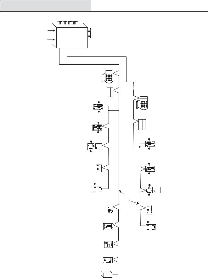
Section 2: System Architecture |
|
||
|
16 zones on board |
|
|
PSTN |
on board |
|
|
(comm 1) |
8 outputs |
|
|
telecom |
|
||
|
area Galaxy 3-48 |
on board |
|
RS232 |
|
|
|
Serial Port |
Line |
|
|
(comm 6) |
1 |
|
|
|
|
Cable run 1 km (max) |
|
|
NOTE: |
* Keypads (8) |
|
* Valid addresses for the |
CP027/ |
|
|
|
keyprox are: |
Keyprox (3) |
|
|
Line 1 (0, 1 & 2). |
CP028 |
|
|
|
|
|
|
This sets the address for both |
|
|
|
the keypad and card reader |
|
|
|
parts of the keyprox. |
* Max (4) |
|
* |
|
|
|
Certain keypad and |
MX03 |
|
|
|
max addresses can |
|
|
|
be replaced by a |
4 outputs |
|
|
combined keyprox unit. |
|
|
RIO (4) |
C072 |
NOTE:
RIOs, RF RIO's and PSU's can be mixed on the lines. The maximum number of combined modules is given in the table below.
8 zones
OR
4 outputs
Smart PSU (4)
P015
8 zones
OR
4 outputs
Power Unit (4) P025
or
Power RIO (4) P026
8 zones
OR
RF RIO Module (4)
C076
Output Module (4) C078
4 - 16 outputs
NOTE: Each Output Module can simulate up to 4 RIO's (outputs only) depending on DIP switch setting.
Valid addresses for the Output Module are the same as standard RIO's.
NOTE:
The Telecom, Printer Interface, RS232, Ethernet and ISDN modules can only be connected to line 1.
If a Telecom module is attached, keypad address E cannot be connected to line 1(address E is shown as 18 on the system).
If an RS232 module is attached, keypad address D cannot be connected to line 1 (address D is shown as 17 on the system).
If an Ethernet module is attached, keypad address B cannot be connected to line 1 (address B is shown as 15 on the system).
If an ISDN module is attached, keypad address C cannot be connected to line 1 (address C is shown as 16 on the system).
Telecom Module (1)
E062 (comm 5) 
RS232 Module (1)
E054 (comm 2)
ISDN Module (1)
E077 (comm 3)
Ethernet Module (1)
E080 (comm 4)
Printer Interface (1)
A134/A161
Twisted Pair
Screened Cable
W002
|
On-board |
|
RIOs/ Smart PSUs/EN51 PSU |
|
Keypads |
Keyprox |
|
MAX |
|||||
|
|
|
|
|
|
|
|
|
|
|
|
|
|
Galaxy Panel |
Zones |
Outputs |
Poss. |
Address |
Zones |
Outputs |
Poss. |
|
Address |
Poss. |
|
Address |
Poss. |
|
|
|
|
|
|
|
|
|
|
|
|
|
|
3-48 (line 1) |
16 |
8 |
4 |
2 - 5 |
32 |
16 |
8 |
|
0, 1 & 2, B, C, D, |
3 |
|
0, 1 & 2 |
4 |
|
|
|
|
|
|
|
|
|
E, F |
|
|
|
|
|
|
|
|
|
|
|
|
|
|
|
|
|
|
Figure 2-1. Galaxy 3-48 System Configuration
2-1
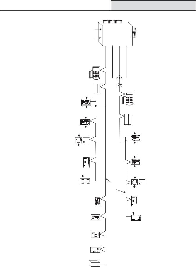
G3-144 Configuration |
Galaxy 3 Series Installation Manual |
||||
|
16 zones on board |
|
|||
PSTN |
on board |
|
|
||
(comm 1) |
|
8 outputs |
|||
telecom |
Galaxy 3-144 |
||||
|
on board |
||||
|
area |
|
|||
RS232 |
|
|
|
|
|
Serial Port |
Line |
Line |
|
||
(comm 6) |
|
||||
1 |
2 |
|
|||
|
|
||||
|
|
|
|
Cable run 1 km (max) |
|
|
NOTE: |
|
|
* Keypads (8) |
|
* Valid addresses for the |
CP027/ |
||||
Keyprox (3) |
|||||
|
keyprox are: |
|
|||
|
|
CP028 |
|||
|
Line 1 (0, 1 & 2). |
||||
|
|
||||
|
Line 2 (0, 1, 2, & 3 ). |
|
|||
|
This sets the address for both |
||||
|
the keypad and card reader |
* Max (4) |
|||
|
parts of the keyprox. |
||||
|
MX03 |
||||
|
|
|
|
||
* |
Certain keypad and |
|
* Keypads (8) |
|
max addresses can |
4 outputs |
|
|
be replaced by a |
CP027/ |
|
|
RIO (8) |
Keyprox (4) |
|
|
combined keyprox unit. |
||
|
C072 |
CP028 |
NOTE: |
|
8 zones |
|
RIOs, RF RIO's and |
|
||
OR |
|
||
PSU's can be mixed on |
4 outputs |
||
|
|||
the lines. The maximum |
|
|
|
number of combined |
Smart PSU (8) |
|
|
modules is given in the |
P015 |
|
|
table below. |
|
8 zones |
|
|
OR |
||
|
|
||
|
4 outputs |
||
Power Unit (8) P025 |
|
||
or |
|
|
|
Power RIO (8) P026 |
|
||
|
8 zones |
||
|
OR |
|
|
|
RF RIO Module (8) |
||
|
C076 |
||
|
Output Module (4) C078 |
||
|
|
4 - 16 outputs |
|
NOTE: Each Output Module can simulate up to 4 RIO's (outputs only) depending on DIP switch setting.
Valid addresses for the Output Module are the same as standard RIO's.
NOTE:
The Telecom, Printer Interface, RS232, Ethernet and ISDN modules can only be connected to line 1.
If a Telecom module is attached, keypad address E cannot be connected to line 1(address E is shown as 18 on the system).
If an RS232 module is attached, keypad address D cannot be connected to line 1 (address D is shown as 17 on the system).
If an Ethernet module is attached, keypad address B cannot be connected to line 1 (address B is shown as 15 on the system).
If an ISDN module is attached, keypad address C cannot be connected to line 1 (address C is shown as 16 on the system).
Telecom Module (1)
E062 (comm 5) 
RS232 Module (1)
E054 (comm 2)
ISDN Module (1)
E077 (comm 3)
Ethernet Module (1)
E080 (comm 4)
Printer Interface (1)
A134/A161
*Max (4) MX03
4 outputs
|
RIO (8) |
|
|
C072 |
|
|
8 zones |
|
|
OR |
|
|
4 outputs |
|
|
Smart PSU (8) |
|
|
P015 |
|
|
8 zones |
|
|
OR |
|
|
4 outputs |
|
|
Power Unit (8) P025 |
|
|
or |
|
Twisted Pair |
Power RIO (8) P026 |
|
8 zones |
||
Screened Cable |
||
OR |
||
W002 |
||
|
||
|
RF RIO Module (8) |
|
|
C076 |
|
|
4 - 16 outputs |
|
|
Output Module (4) |
|
|
C078 |
|
On-board |
|
RIOs/ Smart PSUs/EN51 PSU |
|
Keypads |
|
Keyprox |
|
MAX |
||||||
|
|
|
|
|
|
|
|
|
|
|
|
|
|
|
|
Galaxy Panel |
Zones |
Outputs |
Poss. |
Address |
Zones |
Outputs |
Poss. |
|
|
Address |
|
Poss. |
|
Address |
Poss. |
|
|
|
|
|
|
|
|
|
|
|
|
|
|
|
|
144 (line 1) |
16 |
8 |
8 |
1 - 8 |
64 |
32 |
8 |
|
0 |
- 2, B, C, D, E, F |
3 |
|
|
0-2 |
4 |
(line 2) |
|
|
8 |
0 - 7 |
64 |
32 |
8 |
|
0 |
- 6, F |
4 |
|
|
0-3 |
4 |
|
|
|
|
|
|
|
|
|
|
|
|
|
|
|
|
Figure 2-2. Galaxy 3-144 System Configuration
2-2
Galaxy 3 Series Installation Manual |
|
|
|
G3-520 Configuration |
||||
|
|
|
|
16 zones on board |
|
|
||
|
|
|
PSTN |
on board |
|
|
|
|
|
|
|
|
|
|
8 outputs |
||
|
|
|
|
telecom |
|
|
||
|
|
|
RS232 |
area |
Galaxy 3-520 |
on board |
||
|
|
|
|
|
|
|
|
|
|
|
|
Serial Port |
Line |
Line |
Line |
Line |
|
|
|
|
|
|
||||
|
|
|
|
1 |
2 |
3 |
4 |
|
|
|
|
Cable run 1 km (max) |
|
|
|
|
|
NOTE: |
|
|
|
|
|
|
|
|
* Valid addresses for the |
* Keypads (8) |
|
|
|
|
|
||
keyprox are: |
|
|
|
|
|
|
||
Line 1 (0, 1 & 2). |
|
CP027/ |
|
|
|
|
|
|
|
Keyprox (3) |
|
|
|
|
|
||
Lines 2, 3 & 4 (0-6). |
|
|
|
|
|
|
||
|
CP028 |
|
|
|
|
|
||
This sets the address for both |
|
|
|
|
|
|||
|
|
|
|
|
|
|
||
the keypad and card reader |
|
|
|
|
|
|
|
|
parts of the keyprox. |
|
|
|
|
|
Lines 2, 3 and 4 have the same configuration |
||
* Certain keypad and |
|
|
* Max (8) |
|
|
|
Cable run 1 km (max) |
|
|
|
MX03 |
|
|
|
|||
|
|
|
|
|
|
|
||
max addresses can |
|
|
|
|
|
|
|
|
be replaced by a |
|
|
|
|
|
|
|
* Keypads (8) |
combined keyprox unit. |
|
|
4 outputs |
|
|
|
|
CP027/ |
|
|
RIO (15) |
|
|
|
|
Keyprox (7) |
|
NOTE: |
|
C072 |
|
|
|
|
CP028 |
|
|
|
|
|
|
|
|
|
|
RIOs, RF RIO's and |
|
|
|
|
|
|
* Max (8) |
|
PSU's can be mixed on |
|
|
8 zones |
|
|
|
|
|
the lines. The maximum |
|
OR |
4 outputs |
|
|
|
MX03 |
|
number of combined |
|
|
|
|
|
|
|
|
modules is given in the |
Smart PSU (15) |
|
|
|
|
|
||
table below. |
|
|
|
|
|
|||
|
P015 |
|
|
|
|
|
|
|
|
|
OR |
8 zones |
|
|
|
4 outputs |
|
|
|
|
|
|
|
|||
|
|
4 outputs |
|
|
|
|
|
|
Power Unit (15) P025 |
|
|
|
|
|
|
RIO (16) |
|
|
|
|
|
|
|
C072 |
||
or |
|
|
|
|
|
|
|
|
|
|
|
|
|
|
|
|
|
Power RIO (15) P026 |
|
|
|
|
|
8 zones |
||
|
|
8 zones |
|
|
|
|||
|
|
|
|
|
|
|
||
|
|
OR |
|
|
|
|
|
OR |
|
|
|
|
|
|
|
|
|
|
RF RIO Module (15) |
|
|
|
4 outputs |
|||
|
|
|
|
|
|
|||
|
C076 |
|
|
|
|
|
Smart PSU (16) |
|
|
|
|
|
|
|
|
|
|
|
|
|
|
|
|
|
|
P015 |
|
|
|
|
|
|
|
8 zones |
|
Output Module (4) C078 |
|
|
|
|
OR |
|||
|
|
4 - 16 outputs |
|
|
|
4 outputs |
||
|
|
|
|
|
|
|
||
NOTE: Each Output Module can simulate |
|
|
|
|
|
Power Unit (16) P025 |
||
up to 4 RIO's (outputs only) depending |
|
|
|
|
|
|
||
|
|
|
Twisted Pair |
|
or |
|||
on DIP switch setting. |
|
|
|
|
|
|||
|
|
|
|
|
Power RIO (16) P026 |
|||
|
|
|
|
Screened Cable |
||||
Valid addresses for the Output Module are |
|
|
|
|||||
|
|
W002 |
|
8 zones |
||||
the same as standard RIO's. |
|
|
|
|
|
|||
|
|
|
|
|
|
|
OR |
|
|
|
|
|
|
|
|
|
|
|
|
|
Telecom Module (1) |
|
|
|
|
RF RIO Module (16) |
|
|
|
E062 (comm 5) |
|
|
|
|
|
NOTE: |
|
|
|
|
|
|
|
C076 |
The Telecom, Printer Interface, |
|
|
|
|
|
|
|
|
RS232, Ethernet and ISDN |
|
|
|
|
|
|
|
|
modules can only be |
|
RS232 Module (1) |
|
|
|
4 - 16 outputs |
||
connected to line 1. |
|
|
|
|
|
|
||
If a Telecom module is attached, |
|
E054 (comm 2) |
|
|
|
|
Output Module (4) |
|
keypad address E cannot be |
|
|
|
|
|
|
|
C078 |
connected to line 1(address E is |
|
|
|
|
|
|
|
|
shown as 18 on the system). |
|
|
ISDN Module (1) |
|
|
|
|
|
If an RS232 module is attached, |
|
|
|
|
|
|
|
|
keypad address D cannot be |
|
|
E077 (comm 3) |
|
|
|
|
|
|
|
|
|
|
|
|
|
|
connected to line 1 (address D is |
|
|
|
|
|
|
|
|
shown as 17 on the system). |
|
|
|
|
|
|
|
|
If an Ethernet module is attached, |
|
|
|
|
|
|
|
|
keypad address B cannot be |
|
Ethernet Module (1) |
|
|
|
|
|
|
connected to line 1 (address B is |
E080 (comm 4) |
|
|
|
|
|
||
shown as 15 on the system). |
|
|
|
|
|
|
|
|
If an ISDN module is attached, |
|
|
|
|
|
|
|
|
keypad address C cannot be |
|
Printer Interface (1) |
|
|
|
|
|
|
connected to line 1 (address C is |
|
|
|
|
|
|||
shown as 16 on the system). |
|
A134/A161 |
|
|
|
|
|
|
|
On-board |
|
RIOs/ Smart PSUs/EN51 PSU |
|
Keypads |
|
Keyprox |
|
MAX |
||||||
|
|
|
|
|
|
|
|
|
|
|
|
|
|
|
|
Galaxy Panel |
Zones |
Outputs |
Poss. |
Address |
Zones |
Outputs |
Poss. |
|
|
Address |
|
Poss. |
|
Address |
Poss. |
|
|
|
|
|
|
|
|
|
|
|
|
|
|
|
|
520 (line 1) |
16 |
8 |
15 |
1 - 9, A - F |
120 |
60 |
8 |
|
0 |
- 2, B, C, D, E, F |
3 |
|
|
0-2 |
8 |
(lines 2, 3, 4) |
|
|
16 |
0 - 9, A - F |
384 |
64 |
8 |
|
0 |
- 6, F |
7 |
|
|
0-6 |
8 |
|
|
|
|
|
|
|
|
|
|
|
|
|
|
|
|
Figure 2-3. Galaxy 3-520 System Configuration
2-3

Layout PCB .4-2 Figure 4-2
Telecom
Connect
RS485 line 1
RS485 line 2 (3-144/3-520 only)
RS232 Port
|
|
|
SPI |
|
Telecom |
Memory |
Expansion card |
Program |
|
backup |
Header |
|||
interface |
||||
Socket |
battery |
|
||
|
|
|||
|
|
|
|
|
|
|
|
|
B |
LINE |
|
|
|
|
|
|
|
|
||
A |
|
|
|
|
|
|
|
|
|
||
PHONE |
|
|
|
|
|
A B |
|
|
|
|
|
|
|
|
|
||
|
|
|
|
||
|
|
|
|
||
|
|
|
|
||
|
|
|
|
|
|
|
|
|
|
|
|
B1 |
|
|
|
|
|
|
|
|
|
|
|
A1 |
|
|
|
|
|
|
|
|
|
|
GND +12V
LK3

Engineer socket (RS485 Line1)
MICRO
PROCESSOR
SRAM
TAMPER
OFF WALL
BATTERY
START UP
Jumper Lead for off-wall tamper switch
B2 |
LK5 |
|
|
|
|
|
|
|
|
Horn output |
|
|
|
|
|
|
|
|
|
|
|
volume control |
|
|
|
||
A2 |
|
|
|
|
|
|
|
|
|
|
|
|
|
LED1(for Telecoms) |
|
|
Pull-up switches |
|
|
|
|
|
|||||
GND |
|
FLASH |
|
|
BAT |
|
|
||||||
|
|
|
|
|
|
|
|
|
AC |
Leads for |
|||
+12V |
LED2 (for RS232) |
|
|
|
|
|
|
|
|
BELL |
|||
|
|
|
|
|
|
|
|
|
LID TAMP |
lid tamper |
|||
TX |
(RS485 Line 2) |
|
|
1 |
2 |
3 |
4 5 |
6 7 8 |
SWITCH |
F2 |
F1 |
||
|
Engineer socket |
|
|
ON |
|
|
|
|
RIO |
|
|
|
microswitch |
|
|
|
|
|
|
|
|
|
|
|
|||
|
|
|
|
|
|
|
|
|
|
|
|
|
|
RX |
AUX1 |
|
AUX2 (3-144/3-520 only) |
SW3 |
|
|
|
|
|
|
|
-BAT |
|
|
|
|
|
|
|
|
|
|
|
|
|||
CTS |
F4 |
F3 |
3-144/3-520 only |
|
|
|
|
|
|
|
|
+BAT |
Battery |
|
|
|
|
|
|
|
|
|
|
|
|
terminals |
|
RTS |
RS232 Port socket |
|
|
|
|
|
|
|
|
|
|
14.5 |
|
|
|
|
|
|
|
|
|
|
|
|
N/O C N/C |
|
|
|
|
|
|
|
|
|
|
|
+12V |
|
+12V |
|
|
+12V |
|
+12V |
1 |
2 |
3 |
4 |
+12V |
1 |
2 |
3 |
4 |
AUX |
G |
1 0V 2 |
3 0V 4 |
5 0V 6 |
1 0V 2 |
3 0V 4 |
5 0V 6 |
TAMP |
N |
|||||||||||||
RIO 0 |
7 0V 8 |
RIO 1 |
7 0V 8 |
|
RIO 0 |
|
|
|
RIO |
1 |
|
D |
|
|
|
|
|
|
|
|
|
|
16 on-board zones |
Relay |
External |
|||||||
loudspeaker |
|||||||||
|
|
|
|
Output |
|||||
|
|
|
|
|
|
||||
NOTE: |
Fuse AUX1 controls |
NOTE: |
Zones 1-8 |
(RIO 0 line 1) |
|
|
RS485 line 1, RIO 0 (zones 1-8) |
|
|
|
|
|
|
|
Zones 1-8 |
(RIO 1 line 1 (switch SW3-8 |
OFF)) |
|
Fuse AUX2 controls |
|
|
OR |
|
|
RS485 line 2, RIO 1 (zones 1-8) |
|
Zones 1-8 |
(RIO 1 line 0 (switch SW3-8 |
ON)) |
Layout PCB
Layout PCB
Manual Installation Series 3 Galaxy
Galaxy 3 Series Installation Manual |
RS485 Expansion Module |
|
|
The 7 transistorised outputs on the Galaxy 3 Series can be configured to open collectors by setting the dip switch SW3 to the OFF position.
NOTE: Output 2 on RIO 0 (relay output) is not affected.
The following table shows which outputs are controlled by which switches.
(SW3) |
RIO |
Output |
|
|
|
1 |
0 |
1 |
|
|
|
2 |
0 |
3 |
|
|
|
3 |
0 |
4 |
|
|
|
4 |
1 |
1 |
|
|
|
5 |
1 |
2 |
|
|
|
6 |
1 |
3 |
|
|
|
7 |
1 |
4 |
|
|
|
Table 2-1. SW3 Transistorised Outputs Control
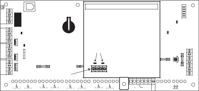
RS485 Expansion Module (G3-520 only)
The RS485 Expansion Module can be attached to the G3-520 to give 2 extra RS485 (AB) lines.
The Expansion module must be wired in a daisy-chain configuration. That is, the A line from the previous module is connected to theA3 orA4 terminal of the Expansion Module.
The RS485 (AB) line must have a 680 ohm resistor fitted across the A and B terminals of the last module on the line. If two lines are connected, both ends must be terminated with a 680 ohm resistor and the appropriate link (LK1 or LK2) removed.
RS485
EXPANSION
MODULE
Jumpers
LK1 |
LK2 |
Twin |
|
RS485 |
|
lines |
A3 B3 A4 B4 |
|
|
|
|
|
|
|
|
|
|
|
|
|
|
|
|
|
|
|
|
|
|
|
|
|
|
|
|
|
|
|
|
|
|
|
|
|
|
|
|
|
|
|
|
|
|
|
|
|
|
|
|
|
|
|
|
|
|
|
|
|
|
|
|
|
|
|
|
|
|
|
|
|
|
|
|
|
|
|
|
|
|
|
|
|
|
|
|
|
|
|
|
|
|
|
|
|
|
|
|
|
|
|
|
|
|
|
|
|
|
|
|
|
|
|
|
|
|
|
|
|
|
|
|
|
|
|
|
|
|
|
|
|
|
|
|
|
|
|
|
|
|
|
|
|
|
|
|
|
|
|
|
|
|
|
|
|
|
|
|
|
|
|
|
|
|
1 |
|
|
|
|
|
|
|
|
|
|
1 |
|
0V 2 |
|
|
|
3 |
|
0V 4 |
+12V |
5 |
|
0V 6 |
|
7 |
|
0V 8 |
|
+12V |
|
1 |
|
0V 2 |
|
|
|
3 |
|
0V 4 |
+12V |
5 |
|
0V 6 |
|
7 |
|
0V 8 |
+12V |
|
|
|
2 |
|
|
3 |
4 |
|||||||||||||||||||||||||||||||||||||||||
|
|
|
|
|
|
RIO 0 |
|
|
|
|
|
|
|
|
|
RIO 1 |
|
|
|
|
|
|
|
|
|
|
RIO 0 |
|
|
||||||||||||||||||||||||||||||||||||||||||||||||||||||||||
+12V
|
|
|
|
|
|
|
|
|
|
|
|
|
|
|
|
|
|
|
|
|
|
|
|
|
|
|
|
|
|
|
|
|
|
|
|
|
|
|
|
|
|
1 |
2 |
3 |
4 |
|
|
|
|
|
|
|
AUX G |
|||||||||
|
|
|
|
|
|
|
TAMP N |
|||||||||||||
|
|
RIO |
1 |
|
|
|
|
|
|
|
|
|
|
|||||||
|
|
|
|
|
|
|
|
|
|
|
|
|
|
|
D |
|||||
Figure 2-5. RS485 Expansion Module
2-5
Installation Recommendations |
Galaxy 3 Series Installation Manual |
|
|
System Installation and Wiring
The installation and wiring must be performed by a competent engineer. For permanently connected equipment, a readily accessible disconnect device must be incorporated in the fixed wiring having contact separation of at least 3 mm on each pole. The Galaxy 3 Series control panel must be connected to the a.c. mains supply (230/240 Va.c. 50 Hz) via a fused connection outlet.
The fuse in the mains outlet must not exceed 3A.
WARNING: A means of isolation from the mains supply must be provided within 2 metres of the control panel. Where live and neutral supplies can be identified, a fused spur with a 3 amp fuse, must be fitted on the live circuit. Where live and neutral circuits cannot be reliably identified, 3 amp fuses must be fitted to both circuits.
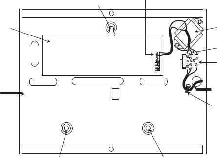
Route the mains cable through the hole on the right hand side of the enclosure base. Securely anchor the cable to the box using the tie-wrap as shown in the following Figure:
|
Keyhole |
AC connect |
|
|
|
|
slot (top) |
|
PCB |
|
Mains |
|
transformer |
|
|
|
|
|
|
Earth wire |
|
|
Terminal |
|
|
block |
Enclosure |
|
Mains cable |
base |
|
Tie wrap
Attaching hole |
Attaching hole |
Figure 2-6. Securing the Mains Cable to the Enclosure Base
Secure the panel base to the wall using three 1.5" No. 8 round head steel screws through the holes provided.
The mains cable used must be a three core type (with green/yellow earth insulation) of adequate current carrying capacity.
NOTE: The mains cable must satisfy the requirements stated in BS6500. Connect the mains cable to the mains terminal block as follows:
•blue wire to the terminal marked N (Neutral)
•green/yellow wire to the terminal marked (Earth)
•brown wire to the terminal marked L (Live)
NOTE: No other connections to the mains connector are permitted.
All wiring must be in accordance with the latest edition of the IEE Wiring Regulations, BS7671 (Requirements for Electrical Installations).
2-6
Galaxy 3 Series Installation Manual |
System Wiring |
|
|
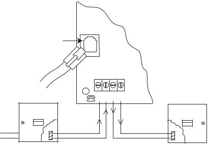
Connecting the Galaxy 3 Series to the PSTN
The Telecommunications Network Voltage (TNV) port (terminalsAand B on PCB) must be permanently connected (hard-wired) to the PSTN via a BT master socket, refer to Figure 2-7.
Note: If the BT master socket is the newer type (NTE5/CTE5), then the connection can be carried out by the installation engineer. If the BT master socket is not an NTE5/CTE5, then the network operator must make the connection.
Telecom
Socket
RJ45
Plug
|
BT Master socket (NTE5/CTE5). |
LINE PHONE |
BT Secondary socket (NTE5/CTE5). |
|
B A B A |
||
Incoming |
2 |
|
5 |
PSTN Line |
5 |
|
2 |
Figure 2-7. Connecting the Galaxy 3 Series to the PSTN
NOTES: 1. Terminals 2 and 5 on the BT Master Socket must be hard-wired to LINEA and B terminals on the Galaxy 3 Series PCB. The connection is polarity independent.
2.It is strongly recommended that the Galaxy 3 Series panel is the only device on the line.
3.If another device is to be connected to the line, connect the PHONE terminals on the PCB to terminals 2 and 5 on a second BT Master Socket.
There are two methods of connecting the on-board Telecom Module to the PSTN:
Method 1
Using cable suitable for connection to 2.8 mm diameter screw terminals, strip back approximately 20 mm of the outer sheath and then remove approximately 4 mm of the insulation from the wires to be connected to the Galaxy 3 Series PCB.
Connect terminals 2 and 5 on the BT Master socket across the LINEAand B terminals on the Galaxy 3 Series PCB, see Figure 2-7.
Method 2
Use a standard cable with RJ45 plug on one end and plug into the telecom socket on the Galaxy 3 Series PCB. Connect the other end of the cable to the BT Master socket as described in Method 1.
2-7
System Wiring (cont’d) |
Galaxy 3 Series Installation Manual |
|
|
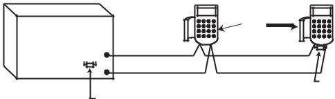
Connecting Additional Telecom Apparatus
A BT secondary socket, allows additional telecom apparatus to be connected in series with the on-board telecom module. Connect the PHONE terminalsAand B on the PCB to the terminals on the BT secondary socket. See Figure 2-7.
Line Monitoring
Under normal idle state conditions, the on-board Telecom Module monitors the RS485 line. The communication status is indicated by the state of the red LED (LED1) as shown in the following table:
LED STATE |
INDICATION |
|
|
|
|
LED OFF |
No d.c. supply to module |
|
|
|
|
ON - 01s, OFF - 0.9s |
Normal communication |
|
|
|
|
Single pulse at end of call |
Normal communcation |
|
|
|
|
Flashing at end of alarm call |
Failed Communication |
|
|
|
|
On during alarm monitoring, galaxy |
Normal Communication |
|
gold and SMS |
||
|
||
Flickering during alarm monitoring, |
Poor communication |
|
galaxy gold and SMS |
||
|
||
Flashes in time with ringing signal |
Line Ringing |
|
Pulses as each digit is dialled |
Normal indication when |
|
making call |
||
|
Table 2-2. Comms Status
2-8

Galaxy 3 Series Installation Manual |
Stand-by Battery |
|
|
Stand-by Battery
The Galaxy 3 Series control panels can accommodate up to 2 x 17Ahr batteries. Ensure that the battery connector leads on the control panel Powers Supply Unit (PSU) are connected to the correct terminals on the battery.
CAUTION: |
There is a risk of explosion if the battery is replaced by an incorrect type. |
|||
|
Dispose of used batteries according to the instructions. |
|||
|
|
|
|
|
|
|
Control Panel |
Battery |
|
|
|
|
|
|
|
|
-BAT |
-ve terminal |
|
|
|
|
|
|
|
|
+BAT |
+ve terminal |
|
|
|
|
|
|
|
Table 2-3. Battery/Control Panel connections |
|||
Battery Start-up
The system can be powered up via the Battery Start-up jumper if there is noAC power. To do this, short out the Battery Start-up jumper for the duration of the configuration process only. Never leave the Battery Start-up connected or else deep discharge of the Stand-by Battery will occur.
On-Board Power Supply Unit
The on-board Power Supply Unit (PSU) supplies and monitors power to the system and peripherals. The following table shows the fuse name and value in amps.
G3-144/G3-520: The Galaxy 3 Series control panel contains four fuses. Details are given in the table below. NOTE: The G3-48 does not require fuseAUX2.
FUSE NAME |
VALUE (AMPS) |
|
MONITORS |
TYPE |
|
|
|
|
|
AUX1 |
1.0 |
RS485 Line 1, |
RIO 0, Zones 1-8: +12V, |
20 mm, anti-surge |
|
|
on-board comms |
|
|
|
|
|
|
|
AUX2 |
1.0 |
RS485 Line 2, |
RIO 1, zones 1-8 +12V |
20 mm, anti-surge |
|
|
|
|
|
BATT |
1.6 |
Battery |
|
20 mm, anti-surge |
|
|
|
|
|
BELL |
1.0 |
Outputs RIO 0 1-4, RIO 1 1-4, Horn output |
20 mm, anti-surge |
|
Table 2-4. On-board PSU Fuses
Power Monitoring Characteristics: |
Low battery level: 11.2V |
|
Deep discharge protection: 10.5V |
|
Overvoltage protection: 14.7V |
G3-48
The PSU total capacity is 1.5A. Internally the PSU is split in two in order to ensure sufficient current is always available for stand-by battery recharge. The PSU capacity is broken down as follows:
• |
Battery: |
0.75A |
• |
Control PCB: |
0.25A |
• |
AUX +12V: |
0.5A |
The PSU is available for zones/outputs and peripherals.
G3-144/520
The PSU total capacity is 2.5A. Internally the PSU is split in two in order to ensure sufficient current is always available for stand-by battery recharge. The PSU capacity is broken down as follows:
• |
Battery: |
1.25A |
• |
Control PCB: |
0.25A |
• |
AUX +12V: |
1.00A |
2-9
Memory |
Galaxy 3 Series Installation Manual |
|
|
Memory
The Galaxy 3 Series control panel is fitted with a memory chip with its own battery backup on the main PCB. This allows the panel to retain the system configuration, programming details and the event log for up to a year when both the mains power and standby battery have been disconnected. The memory backup battery must be kept in place to retain the memory during a mains failure. Re-apply power, this is known as a warm start.
To completely erase the system memory and return to the default settings, place a piece of thin card between the retaining clip and the memory backup battery then remove all power to the PCB for one minute. Re-apply power and remove the card. This is known as a cold start.
The memory backup battery shoud be replaced every 5 years.
CAUTION: |
There is a risk of explosion if the battery is replaced by an incorrect type. |
|
Dispose of used batteries according to the instructions. |
CAUTION: |
Do not overstress the retaining clip when removing and installing the backup |
|
battery. The clip must maintain a firm pressure on the backup battery at all times. |
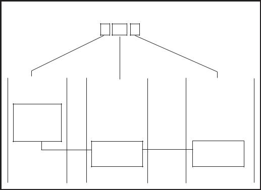
RS485 Data Communication Bus (AB Lines)
Communication between the Galaxy control panels and the modules attached to the system takes place on the AB lines. The communication protocol is RS 485 format. The control panel constantly monitors the modules attached to it.Abreak in the communication from any of the modules generates a module tamper alarm
RS485 Wiring Configurations
The system must be wired in a daisy-chain configuration. That is the A line from the previous module is connected to the A terminal of the current module and then on to the A line of the next module.
The RS485 (AB) line must have a 680 Ωresistor fitted across the A and B terminals of the last module on the line. If two lines are connected, both ends must be terminated with 680 Ωresistors and the appropriate link (LK3 or LK5) removed.
|
|
|
Keypad/Keyprox |
|
|
|
|
|
OR |
|
|
Galaxy |
|
|
Module |
|
|
|
|
|
|
||
Control |
A |
B |
A |
B |
|
Panel |
|||||
A |
|
|
|
||
680 Ω |
|
|
|
||
B |
|
|
|
||
|
|
|
680 Ω EOL |
||
|
|
|
|
||
|
Fit LK3/LK5 on PCB |
|
|
|
Figure 2-8. Daisy Chain Configuration
Each AB line can run in two directions from the control panel.
•Remove link LK3 (RS485 line1) or link LK5 (RS485 line2).
•Run two lines from theAand B terminals of the line.
•Terminate both Ends of Line (EOL) with a 680 ohm resistor.
NOTE: It is permissable to have different configurations on each line. For example, line 1 - Daisy chain; line 2 - twinAB daisy chain.
2-10
Galaxy 3 Series Installation Manual |
RS485 Recommendations |
|
|
Keypad/Keyprox |
Keypad/Keyprox |
OR |
OR |
Module |
Module |
|
|
Galaxy |
|
|
Control |
A |
B |
Panel |
A |
A |
B |
B |
|
|
680 Ω EOL |
|
|
680 Ω EOL |
|
|
|
Remove |
|
|
|
LK3/LK5 |
|
|
|
|
|
Figure 2-9. TwinAB Line Daisy-Chain configuration |
||
RS485 Wiring Recommendations
To ensure that the system communicates at the maximum level of efficiency, the following recommendations must be adhered to:
1.Each communication line can support 32 devices. The maximum number of devices on each line are:
|
Galaxy 3-48 |
Galaxy 3-144 |
Galaxy 3-520 |
|
|
(Line 1 only) |
(Lines 1-2) |
(Lines 1-4) |
|
Keypads |
8 |
8 per line |
8 per line |
|
|
|
|
|
|
Keyprox |
3 |
3 (line 1) |
3 (line 1) |
|
4 (line 2) |
7(lines 2, 3, 4) |
|||
|
|
|||
RIO's/SPSU's |
4 |
8 per line |
15 (line1) |
|
16 (lines 2, 3, 4) |
||||
|
|
|
||
Output Module |
4 |
4 per line |
4 per line |
|
|
|
|
|
|
RF RIO |
4 |
8 per line |
15 (line 1) |
|
16 (lines 2, 3, 4) |
||||
|
|
|
||
MAX |
4 |
4 per line |
8 per line |
|
|
|
|
|
|
RS232 |
1 |
1 (line 1 only) |
1 (line 1 only) |
|
|
|
|
|
|
Telecoms |
1 |
1 (line 1 only) |
1 (line 1 only) |
|
|
|
|
|
|
Printer |
1 |
1 (line 1 only) |
1 (line 1 only) |
|
|
|
|
|
|
ISDN |
1 |
1 (line 1 only) |
1 (line 1 only) |
|
|
|
|
|
|
Ethernet |
1 |
1 (line 1 only) |
1 (line 1 only) |
|
|
|
|
|
Table 2-5. Communication Devices
2.The system must be wired in a daisy-chain configuration. Spur and star configurations must not be used as they reduce the immunity to electrical interference.
3.The cable used to connect the RS485 (AB) line must be screened twisted pair (Part No. W002) or Belden 8723 equivalent.
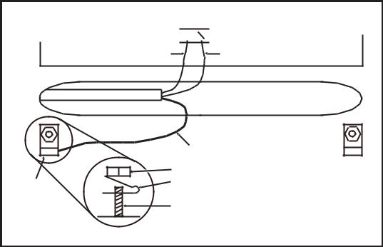
4.Shielded twisted pair cable, where used, is connected to the earthing pillar on the Galaxy control panel using the P-clip and nut supplied (refer to Figure 2-10).
5.The RS485 (AB) line must have a 680 Ωresistor fitted across the A and B terminals of the last module on the line. If twin lines are connected, both ends must be terminated with 680 Ωresistors and the appropriate link on the control panel PCB must be removed (refer to figure 2-9).
2-11
RS485 Recommendations |
Galaxy 3 Series Installation Manual |
|
|
6.There must only be a single AB pair of wires in each of the cables.
7.The minimum voltage level is 10.5 Vd.c. with 12.5 Vd.c. being the recommended working minimum.
8.The power supply in the Galaxy control panel and remote power supplies must not be connected inparallel.
9.The 0 V of all remote power supplies should be connected in common to the 0 V of the Galaxy control panel.
10.Ensure that any extension loudspeakers are not wired in the same cable as an AB pair of wires.
11.Where possible, ensure that the AB cable is at least 30 centimetres away from any other cables.
12.Where possible, ensure that the AB cable does not run parallel to other cables for extended distances (maximum 5 metres).
AB connectors
A 


 B
B
data line |
data line |
RS 485 cable
Cable screen
|
Nut |
P-clip |
P-clip |
|
Earthing pillar |
(threaded) |
Figure 2-10. Connection of cable screen using P-Clip
2-12
Galaxy 3 Series Installation Manual |
Zone Addresses |
|
|
Zones
The default setting for the zones on the Galaxy 3 Series are shown in the following table:
|
|
|
|
|
Galaxy |
Zone 1001 |
Zone 1002 |
Remaining |
|
Panel |
Zones |
|||
|
|
|||
3-48 |
Final |
Exit |
Intruder |
|
|
|
|
|
|
3-144 |
Final |
Exit |
Intruder |
|
|
|
|
|
|
3-520 |
Final |
Exit |
Intruder |
|
|
|
|
|
Zone Addresses
Table 2-6. Default Zone Functions
Each zone has a four digit address; 1004, 4136. The address is made up of three reference numbers as shown inthefollowingfigure:
|
Example: 3057 |
|
||
|
3 |
05 |
7 |
|
Represents Panel |
Represents |
|
Represents |
|
Line No. |
RIO Address |
Zone No. 1-8 on |
||
|
|
|
|
RIO |
GALAXY |
|
|
|
|
G3 PANEL |
|
|
|
|
1 2 3 4 |
|
|
|
|
|
RIO |
|
|
ZONE 7 |
|
ADDRESS 05 |
|||
|
|
|||
Figure 2-11. Zone Addresses
For example, zone 3057 is the detector connected to line 3, RIO 05, zone 7.
2-13
RIO Switch |
Galaxy 3 Series Installation Manual |
|
|
Zone Addressing with Onboard RIO Switch
The RIO switch (SW3, dipswitch 8) controls the ordering of the on-board RIO’s. This dipswitch must be set before powering up the panel.
NOTE: The RIO switch is not functional on the 3-48. It defaults to the Switch off configuration.
Switch off (default)
When the switch is set to this mode, the onboard RIO’s configure to the following addresses: |
||||
Onboard RIO0 |
Zone address range: |
1001-1008 |
Outputs: |
1001-1004 |
Onboard RIO1 |
Zone address range: |
1011-1018 |
Outputs: |
1011-1014 |
Switch on
When the switch is set to this mode, the onboard RIO’s configure to the following addresses: |
|||||||||||
Onboard RIO0 |
Zone address range: |
1001-1008 |
Outputs: |
1011-1014 |
|||||||
Onboard RIO1 |
Zone address range: |
0011-0018 |
Outputs: |
0011-0014 |
|||||||
|
|
|
|
|
|
|
|
||||
|
PANEL |
ON-BOARD RIO RANGE |
TOTAL |
|
RIO's |
|
TOTAL |
||||
|
|
|
|
|
|
|
|
|
|
|
|
|
3-48 |
|
1001 |
- 1008, 1011 |
- 1018 |
|
16 |
|
Line 1 (4) |
|
48 |
|
|
|
|
|
|
|
|
|
|
|
|
|
3-144 |
|
1001 |
- 1008, 1011 |
- 1018, |
16 |
|
Line 1 (8) |
|
144 |
|
|
|
|
0011 |
- 0018 (switch on) |
|
|
|
Line 2 (8) |
|
|
|
|
|
|
|
|
|
|
|
|
|
|
|
|
3-520 |
|
1001 |
- 1008, 1011 |
- 1018, |
16 |
|
Line 1 (15) |
|
520 |
|
|
|
|
0011 |
- 0018 (switch on) |
|
|
|
Line 2 (16) |
|
|
|
|
|
|
|
|
|
|
|
|
Line 3 (16) |
|
|
|
|
|
|
|
|
|
|
|
Line 4 (16) |
|
|
|
|
|
|
|
|
|
|
|
|||
|
|
|
|
Table 2-7. Zone Address Ranges |
|
|
|||||
Wiring Zones
The zones on Galaxy 3 Series panels can be Double Balanced (default) or End of Line. Zones can be programmed with different resistance ranges for zone status activation (see Galaxy 3 Series Programming Manual, IP1-0033, parameter 51.46 = Parameters.Zone Resistance). Refer to Table 2-8 (Double Balanced) or Table 2-9 (End of Line) for details of the zone resistance and resulting conditions.
NOTE: The circuit debounce time (the period the zone must remain in a state to register a change in condition) is 300 milliseconds by default.
|
Preset 1 - 1k |
Preset 2 - 2k2 |
Preset 3 - 4k7 |
|
|
|
|
|
|
Tamper S/C |
0 - 800 |
0 - 1800 |
0 - 3700 |
|
|
|
|
|
|
Low Res |
800 - 900 |
1800 - 2000 |
3700 - 4200 |
|
|
|
|
|
|
Normal |
900 - 1200 |
2000 - 2500 |
4200 - 5500 |
|
|
|
|
|
|
High Res |
1200 - 1300 |
2500 - 2700 |
5500 - 6500 |
|
|
|
|
|
|
Open |
1300 - 12000 |
2700 - 12000 |
6500 - 19000 |
|
|
|
|
|
|
Masked |
12000 - 15000 |
12000 - 15000 |
19000 |
- 22000 |
|
|
|
|
|
Tamper O/C |
15000 - infinity |
15000 - infinity |
22000 |
- infinity |
|
|
|
|
|
Table 2-8. Double Balanced Zone
Resistance and Conditions
|
Preset 1 - 1k |
Preset 2 - 2k2 |
Preset 3 - 4k7 |
|
|
|
|
Tamper S/C |
0 - 800 |
0 - 1800 |
0 - 3700 |
|
|
|
|
Low Res |
800 - 900 |
1800 - 2000 |
3700 - 4200 |
|
|
|
|
Normal |
900 - 1200 |
2000 - 2500 |
4200 - 5500 |
|
|
|
|
High Res |
1200 - 1300 |
2500 - 2700 |
5500 - 6500 |
|
|
|
|
Masked |
1300 - 12000 |
2700 - 12000 |
6500 - 19000 |
|
|
|
|
Open |
12000 - infinity |
12000 - infinity |
19000 - infinity |
|
|
|
|
Table 2-9. End of Line Zone Resistance
and Conditions
2-14
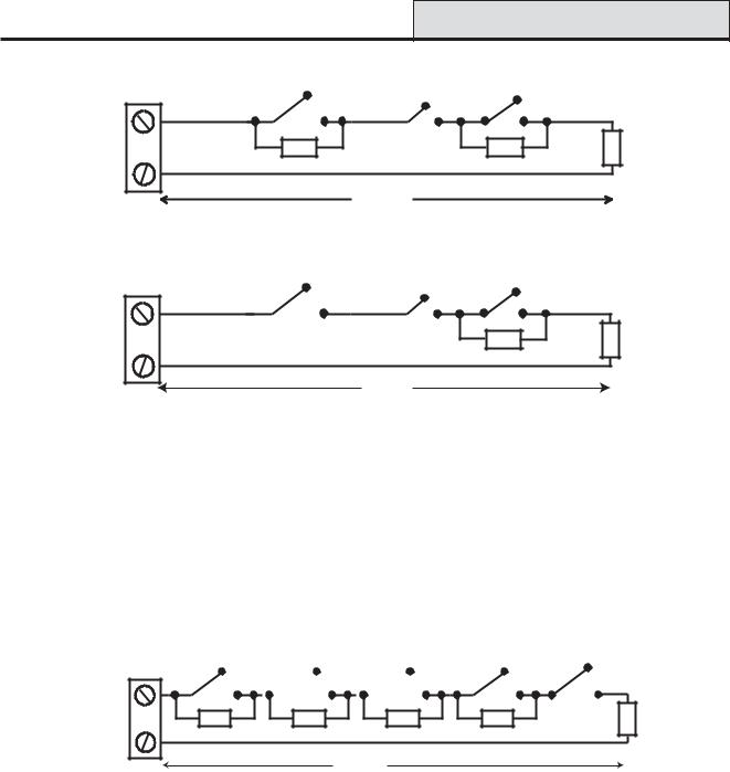
Galaxy 3 Series Installation Manual |
|
Zone Wiring |
Alarm |
|
Anti-mask |
|
Tamper |
|
|
|
|
N/C |
N/C |
N/C |
Zone |
1k |
12k |
1% |
1k |
1% |
|
1% |
|
|
|
|
|
|
|
|
|
500 m
Figure 2-12. Preset 1 - Double balanced Zone/Detector wiring
Alarm |
|
Anti-mask |
|
|
|
|
Tamper |
|
|
||
|
|
|
|
|
|
N/C |
N/C |
|
N/C |
|
|
Zone |
|
12k |
1% |
1k |
1% |
|
|
|
|
|
|
500 m
Figure 2-13. Preset 1 - End of Line Zone/Detector wiring
NOTE: N/C = Normally Closed
NOTE: The recommended maximum cable run from a zone to a detector is 500 metres.
Wiring Multiple Zones
Multiple detectors can be wired into a single zone as shown in the following Figure. The maximum number of detectors that can be connected to a single zone is ten.
|
Alarm |
N/C |
N/C |
Zone |
1k |
|
1% |
Alarm
 N/C
N/C
1k |
1% |
Alarm
 N/C
N/C
1k |
1% |
Alarm (10 max) |
|
|
N/C |
N/C TAMP |
|
1k |
1% |
1k |
1% |
|
|
500 m
Figure 2-14. Zone to Multiple Detector Wiring
Wiring Keyswitches
Latching or spring loaded keyswitches can be used to set and unset the Galaxy panels; option 52 = PROGRAM ZONES has provision to accommodate both types of transition.
If the keyswitch latches, the transition from 1 kΩto 2 kΩinitiates the setting procedure of an unset system, the transition from 2 kΩto 1 kΩinstantly unsets a set system. If the system is already set, then the transition from 1 kΩto 2 kΩhas no effect. If the system is unset, the transition from 2 kΩto 1 kΩhas no effect. This is programmed as a Keyswitch in the PROGRAM ZONES option.
If the keyswitch is spring-loaded (returns to its normal position), the transition from 1 kΩto 2 kΩinitiates the setting procedure of an unset system and instantly unsets a set system, the transition from 2 kΩto 1 kΩ- the return to the normal position - has no effect. This is programmed as a Keyswitch in the PROGRAM ZONES option.
2-15
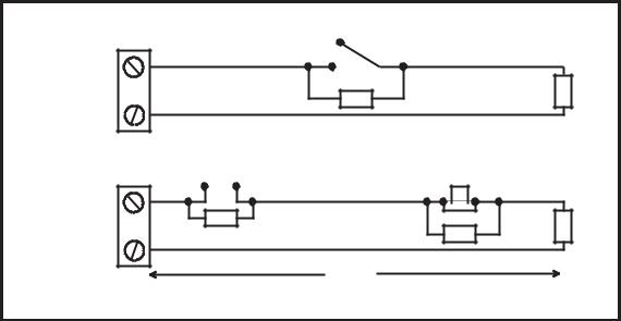
Terminator Zone Wiring |
Galaxy 3 Series Installation Manual |
|
|
Wiring Terminator Buttons
Zones programmed as Push-Set (terminator) buttons can be open going closed (2 kΩto 1 kΩ) or closed going open (1 kΩto 2 kΩ). The first activation of the terminator button initialises its status to the system.
NOTE: The first activation of a terminator may not set the system as this can be the initialisation routine. If the system continues setting, push the button again. The system will set on the second push. This initialisation only occurs on the first setting.All subsequent setting routines set on the first push of the terminator.
The wiring of the terminator and keyswitch zone type is shown in the following figure:
Keyswitch |
1k to unset, 2k to set |
1k |
|
zone |
1k |
||
|
|||
|
1% |
|
1%
Open - Closed |
OR |
Closed - Open |
||||||
|
|
|
|
|
|
|
|
|
|
|
|
|
|
|
|
|
|
|
|
|
|
|
|
|
|
|
|
|
|
|
|
|
|
|
|
Push-set |
1k |
zone |
1% |
|
1% |
1k |
1k |
1% |
|
|
500m
Figure 2-15. Terminator and Keyswitch Zone Wiring
Outputs
The Galaxy 3 Series control panel on-board outputs are detailed in the following table:
Output Address |
Default |
|
|
Normal State |
||
|
|
Type |
Rating |
|||
Default |
Line 0 Enable |
Function |
(with 3k3 pull-up) |
|||
|
|
|||||
|
|
|
|
|||
|
|
|
|
|
|
|
1001 |
1001 |
Bells |
Transistorised |
12V, 400mA |
Positive |
|
|
|
|
|
|
|
|
1002 |
1002 |
Strobe |
Single Pole |
30V, 1A |
De-energised |
|
|
|
|
Change Over |
|
|
|
|
|
|
Relay (SPCO) |
|
|
|
|
|
|
|
|
|
|
1003 |
1003 |
PA |
Transistorised |
12V, 400mA |
Positive |
|
|
|
|
|
|
|
|
1004 |
1004 |
Reset |
Transistorised |
12V, 400mA |
Positive |
|
|
|
|
|
|
|
|
1011 |
0011 |
Set |
Transistorised |
12V, 400mA |
Positive |
|
|
|
|
|
|
|
|
1012 |
0012 |
Intruder |
Transistorised |
12V, 400mA |
Positive |
|
|
|
|
|
|
|
|
1013 |
0013 |
Confirm |
Transistorised |
12V, 400mA |
Positive |
|
|
|
|
|
|
|
|
1014 |
0014 |
Reset |
Transistorised |
12V, 400mA |
Positive |
|
|
|
|
|
|
|
|
Table 2-10. Outputs
2-16

Galaxy 3 Series Installation Manual |
Output Applications |
|
|
Output Applications
The outputs on the Galaxy panels, with the exception of the SPCO relay output, are transistorised outputs; negative applied (positive removed) by default. These supply up to 400 mA and can be used to drive the necessary output devices.
NOTE: The polarity of each output can be changed using option 53 = PROGRAM OUTPUTS
Transistorised Output
+12 V
3k3Ω
Output
0 V
Cut 3k3Ω to give open collector
|
Typical Applications |
A) LED |
|
Output |
LED |
|
|
|
+12 V |
|
1kΩ (typical) |
B) Bell |
Bell |
Output |
 + 12 V
C) Output used to trigger zone
Output
|
1kΩ |
1% |
|
|
zone |
Output must be |
1kΩ |
1% |
open collector |
|
|
Figure 2-16. Output Configuration and TypicalApplications
Note: For the appropriate 3k3Ωpull-up resistor refer to DIP switch SW3 (Table 2-1).
The relay output is a single pole change over; this can be used to drive output devices that require a clean set of contacts, isolated from the output voltage.
|
Horn |
|
Normally |
+12 V |
|
closed |
||
|
||
Single Pole |
|
|
Change - 0ver |
|
|
relay contacts |
|
|
Normally open |
0 V |
|
|
Figure 2-17. Single Pole Change–Over Relay Output Configuration and Typical application
2-17
Loading...