


 Loading...
EQUIP™ Series
Indoor Fixed Mini Dome
Network Camera
NTSC / PAL
HD3MDIP HD3MDIPX
User Guide
Document 800-04132V1 – Rev A – 01/10

Revisions
Issue |
Date |
Revisions |
|
|
|
A |
09/09 |
New document for HD3MDIP/X release. Generally describes the functionality in the |
|
|
firmware of the HD3MDIP/X camera. |
|
|
|
V1 A |
01/10 |
New version number and release date. |
|
|
|
|
|
|
|
|
|
|
|
|
|
|
|
2

HD3MDIP/X Network Camera Reference Guide
Contents
Figures. . . . . . . . . . . . . . . . . . . . . . . . . . . . . . . . . . . . . . . . . . . . . . . . . . 5
Tables . . . . . . . . . . . . . . . . . . . . . . . . . . . . . . . . . . . . . . . . . . . . . . . . . . 7
About This Document . . . . . . . . . . . . . . . . . . . . . . . . . . . . . . . . . . . . . . . . . . . . . 9
Overview of Contents. . . . . . . . . . . . . . . . . . . . . . . . . . . . . . . . . . . . . . . . . . . . 9
Cautions and Warnings . . . . . . . . . . . . . . . . . . . . . . . . . . . . . . . . . . . . . . . . . 10
FCC Compliance Statement . . . . . . . . . . . . . . . . . . . . . . . . . . . . . . . . . . . . . . . 10
Manufacturer’s Declaration of Conformance. . . . . . . . . . . . . . . . . . . . . . . . . . . . . . . 11
North America. . . . . . . . . . . . . . . . . . . . . . . . . . . . . . . . . . . . . . . . . . . 11
Europe . . . . . . . . . . . . . . . . . . . . . . . . . . . . . . . . . . . . . . . . . . . . . . 11
Warranty and Service. . . . . . . . . . . . . . . . . . . . . . . . . . . . . . . . . . . . . . . . . . . 11
1Introduction . . . . . . . . . . . . . . . . . . . . . . . . . . . . . . . . . . . . . . . . . . . . . . 13
Features . . . . . . . . . . . . . . . . . . . . . . . . . . . . . . . . . . . . . . . . . . . . . . . . . |
13 |
2Installation and Setup. . . . . . . . . . . . . . . . . . . . . . . . . . . . . . . . . . . . . . . . . 15
|
Before You Begin . . . . . . . . . . . . . . . . . . . . . . . . . . . . . . . . |
. . . . . . . . . . . . . . 15 |
|
Unpack Everything . . . . . . . . . . . . . . . . . . . . . . . . . . |
. . . . . . . . . . . . . . 15 |
|
Equipment Required . . . . . . . . . . . . . . . . . . . . . . . . . . |
. . . . . . . . . . . . . 16 |
|
Overview of Installation Procedure . . . . . . . . . . . . . . . . . . . . . . . . |
. . . . . . . . . . . . . 16 |
|
Camera Components and Functions . . . . . . . . . . . . . . . . . . . . . . |
. . . . . . . . . . . . . 17 |
|
Camera Installation . . . . . . . . . . . . . . . . . . . . . . . . . . . . . . . . |
. . . . . . . . . . . . . 18 |
|
Preparing the Camera . . . . . . . . . . . . . . . . . . . . . . . . . |
. . . . . . . . . . . . . 18 |
|
Preparing the Mounting Surface . . . . . . . . . . . . . . . . . . . . |
. . . . . . . . . . . . . 18 |
|
Connecting the Wires. . . . . . . . . . . . . . . . . . . . . . . . . . |
. . . . . . . . . . . . . 19 |
|
Mounting the Camera. . . . . . . . . . . . . . . . . . . . . . . . . . |
. . . . . . . . . . . . . 24 |
|
Restore Factory Defaults . . . . . . . . . . . . . . . . . . . . . . . . |
. . . . . . . . . . . . . 25 |
|
Adjusting the Camera FOV (Field of View) . . . . . . . . . . . . . . . . . . . . |
. . . . . . . . . . . . . 25 |
|
Adjusting the Lens Focus. . . . . . . . . . . . . . . . . . . . . . . . |
. . . . . . . . . . . . . 26 |
|
Securing the Enclosure Cover . . . . . . . . . . . . . . . . . . . . . . . . . . |
. . . . . . . . . . . . . 27 |
3 |
Installing the Honeywell IP Utility and HD3MDIP/X Web-Client Software |
. . . . . . . . . . . . . 29 |
|
About the Honeywell IP Utility and Web-Client. . . . . . . . . . . . . . . . . . |
. . . . . . . . . . . . . 29 |
|
About the Honeywell IP Utility . . . . . . . . . . . . . . . . . . . . . |
. . . . . . . . . . . . . 29 |
|
About the Web-Client . . . . . . . . . . . . . . . . . . . . . . . . . . |
. . . . . . . . . . . . . 30 |
|
User Profiles: Honeywell IP Utility and Web-Client . . . . . . . . . . . |
. . . . . . . . . . . . . 30 |
|
Step 1: Confirm Your System Requirements. . . . . . . . . . . . . . . . . . . |
. . . . . . . . . . . . . 31 |
|
Step 2: Install the Honeywell IP Utility Software . . . . . . . . . . . . . . . . . |
. . . . . . . . . . . . . 32 |
|
Downloading the EQUIP Series Installation Guides . . . . . . . . . . |
. . . . . . . . . . . . . 32 |
|
Step 3: Log Onto the IP Utility and Discover Network Devices . . . . . . . . . |
. . . . . . . . . . . . . 33 |
|
Step 4: Connect to a Device and Configure Network Settings . . . . . . . . . |
. . . . . . . . . . . . . 34 |
|
Connecting to or Disconnecting From Devices . . . . . . . . . . . . |
. . . . . . . . . . . . . 35 |
|
Configuring the IP Network Settings Automatically or Manually. . . . |
. . . . . . . . . . . . . 35 |
|
Interfacing with the EQUIP Device Via a Network Video Recorder . . |
. . . . . . . . . . . . . 38 |
Document 800-04132V1 – Rev A – 01/10 |
3 |

Contents
|
Step 5: Launch the Web-Client to View Live Video . . . . . . . . . |
. . . . . . . . . . . . . . . . . . . 38 |
|
Uninstalling IP Utility, Bonjour or the ActiveX Plug-in Software . . . |
. . . . . . . . . . . . . . . . . . . 40 |
|
Uninstalling IP Utility Using the Start Menu . . . . . . . . |
. . . . . . . . . . . . . . . . . . . 41 |
|
Uninstalling IP Utility or IP ActiveX Using the Control Panel |
. . . . . . . . . . . . . . . . . . . 41 |
4 |
IP Camera Web-Client . . . . . . . . . . . . . . . . . . . . . . |
. . . . . . . . . . . . . . . . . . 43 |
|
Overview . . . . . . . . . . . . . . . . . . . . . . . . . . . . . . . |
. . . . . . . . . . . . . . . . . . . 43 |
|
User Profiles . . . . . . . . . . . . . . . . . . . . . . . . |
. . . . . . . . . . . . . . . . . . . 44 |
|
Logging On and Off the HD3MDIP/X IP Web-Client . . . . . . . . . |
. . . . . . . . . . . . . . . . . . . 44 |
|
Launching the Web-Client from IP Utility . . . . . . . . . . |
. . . . . . . . . . . . . . . . . . . 45 |
|
Logging Onto the Web-Client from Internet Explorer . . . |
. . . . . . . . . . . . . . . . . . . 46 |
|
Logging Out of the Web-Client . . . . . . . . . . . . . . . |
. . . . . . . . . . . . . . . . . . . 46 |
|
Navigating the User Interface . . . . . . . . . . . . . . . . . . . . |
. . . . . . . . . . . . . . . . . . . 47 |
|
Live View . . . . . . . . . . . . . . . . . . . . . . . . . . . . . . . |
. . . . . . . . . . . . . . . . . . . 49 |
|
Device Settings . . . . . . . . . . . . . . . . . . . . . . . . . . . . |
. . . . . . . . . . . . . . . . . . . 49 |
|
IP and Firmware Settings on the Device Information Tab . |
. . . . . . . . . . . . . . . . . . . 50 |
|
Compression Settings . . . . . . . . . . . . . . . . . . . . . . . . |
. . . . . . . . . . . . . . . . . . . 51 |
|
Video Codec Settings Tab . . . . . . . . . . . . . . . . . |
. . . . . . . . . . . . . . . . . . . 52 |
|
Statistics: Received Bit Rate and Frame Rate . . . . . . . |
. . . . . . . . . . . . . . . . . . . 54 |
|
Camera Setup . . . . . . . . . . . . . . . . . . . . . . . . . . . . |
. . . . . . . . . . . . . . . . . . . 55 |
|
Auto Exposure . . . . . . . . . . . . . . . . . . . . . . . |
. . . . . . . . . . . . . . . . . . . 55 |
|
White Balance. . . . . . . . . . . . . . . . . . . . . . . . |
. . . . . . . . . . . . . . . . . . . 57 |
|
Video Analytics . . . . . . . . . . . . . . . . . . . . . . . . . . . . |
. . . . . . . . . . . . . . . . . . . 57 |
|
Sabotage Detection. . . . . . . . . . . . . . . . . . . . . |
. . . . . . . . . . . . . . . . . . . 58 |
|
Configuring Video Motion Detection . . . . . . . . . . . . |
. . . . . . . . . . . . . . . . . . . 61 |
|
Alarm and Audio . . . . . . . . . . . . . . . . . . . . . . . . . . . |
. . . . . . . . . . . . . . . . . . . 62 |
|
Alarm Settings . . . . . . . . . . . . . . . . . . . . . . . |
. . . . . . . . . . . . . . . . . . . 62 |
|
Audio Settings . . . . . . . . . . . . . . . . . . . . . . . |
. . . . . . . . . . . . . . . . . . . 63 |
Appendix A Mounting Template. . . . . . . . . . . . . . . . . . . . . . . . . . . . . . . . . . . . 65 Appendix B Troubleshooting . . . . . . . . . . . . . . . . . . . . . . . . . . . . . . . . . . . . . 67
Technical Support . . . . . . . . . . . . . . . . . . . . . . . . . . . . . . . . . . . . . . . . . . . . . 67 Problem: Lens Out of Optical Focus . . . . . . . . . . . . . . . . . . . . . . . . . . . . . . . . . . . . 67 Problem: Live View Does Not Display the Expected Video . . . . . . . . . . . . . . . . . . . . . . . . 68 Problem: Cannot Connect to a Device. . . . . . . . . . . . . . . . . . . . . . . . . . . . . . . . . . . 68
Appendix C |
Specifications . . . . . . . . . . . . . . . . . . . . . . . . . . . . . . . . . |
. . . . . 69 |
|||
Appendix D |
Glossary . . . . . . . . . . |
. . |
. . . . . . . . . . . . . . . . . . . . . . . . |
. . . . . |
73 |
Index . . . . . . . . . . . . . . . . . . . . . . |
. . |
. . . . . . . . . . . . . . . . . . . . . . . . . . . . . |
75 |
||
4

HD3MDIP/X Network Camera Reference Guide
Figures |
|
|
Figure 2-1 |
HD3MDIP/X Camera Components . . . . . . . . . . . . . . . . . . . . . . . . . . . . . . |
17 |
Figure 2-2 |
Mounting Template . . . . . . . . . . . . . . . . . . . . . . . . . . . . . . . . . . . . . . |
18 |
Figure 2-3 |
Audio and Alarm PINs . . . . . . . . . . . . . . . . . . . . . . . . . . . . . . . . . . . . . |
19 |
Figure 2-4 |
Normal Alarm States . . . . . . . . . . . . . . . . . . . . . . . . . . . . . . . . . . . . . . |
20 |
Figure 2-5 |
Alarm Connection . . . . . . . . . . . . . . . . . . . . . . . . . . . . . . . . . . . . . . . |
20 |
Figure 2-6 |
Camera and Cables . . . . . . . . . . . . . . . . . . . . . . . . . . . . . . . . . . . . . . |
22 |
Figure 2-7 |
Wiring Connection Shown on Board . . . . . . . . . . . . . . . . . . . . . . . . . . . . . |
22 |
Figure 2-8 |
Gimbal Adjustment . . . . . . . . . . . . . . . . . . . . . . . . . . . . . . . . . . . . . . |
26 |
Figure 2-9 |
Installing the Enclosure Cover. . . . . . . . . . . . . . . . . . . . . . . . . . . . . . . . . |
27 |
Figure 3-1 |
Accessing Your Installation Documents. . . . . . . . . . . . . . . . . . . . . . . . . . . . |
32 |
Figure 3-2 |
Honeywell IP Utility Log On Window . . . . . . . . . . . . . . . . . . . . . . . . . . . . . |
33 |
Figure 3-3 |
Honeywell IP Utility User Interface. . . . . . . . . . . . . . . . . . . . . . . . . . . . . . . |
34 |
Figure 3-4 |
Set the IP Network Settings Automatically or Manually . . . . . . . . . . . . . . . . . . . . |
36 |
Figure 3-5 |
ActiveX Prompt. . . . . . . . . . . . . . . . . . . . . . . . . . . . . . . . . . . . . . . . . |
39 |
Figure 3-6 |
Web-Client Interface After Logging On . . . . . . . . . . . . . . . . . . . . . . . . . . . . |
40 |
Figure 4-1 |
Launching the HD3MDIP/X Web-Client from IP Utility . . . . . . . . . . . . . . . . . . . . |
45 |
Figure 4-2 |
Web-Client Window Layout: Administrator Log On . . . . . . . . . . . . . . . . . . . . . . |
47 |
Figure 4-3 |
Web-Client: Administrator User . . . . . . . . . . . . . . . . . . . . . . . . . . . . . . . . |
48 |
Figure 4-4 |
Web-Client: Guest User . . . . . . . . . . . . . . . . . . . . . . . . . . . . . . . . . . . . |
49 |
Figure 4-5 |
Device Settings . . . . . . . . . . . . . . . . . . . . . . . . . . . . . . . . . . . . . . . . |
50 |
Figure 4-6 |
IP and Firmware Settings: Device Information Tab . . . . . . . . . . . . . . . . . . . . . . |
51 |
Figure 4-7 |
Compressions Settings Tab: Primary Stream . . . . . . . . . . . . . . . . . . . . . . . . . |
52 |
Figure 4-8 |
Video Codec Settings Tab Available Functions . . . . . . . . . . . . . . . . . . . . . . . |
52 |
Figure 4-9 |
Video Codec Settings, Quality Priority Selected . . . . . . . . . . . . . . . . . . . . . . . |
54 |
Figure 4-10 |
Camera Setup . . . . . . . . . . . . . . . . . . . . . . . . . . . . . . . . . . . . . . . . . |
55 |
Figure 4-11 |
Video Analytics Tab . . . . . . . . . . . . . . . . . . . . . . . . . . . . . . . . . . . . . . |
58 |
Figure 4-12 |
Tamper Detection Settings on the Video Analytics Tab. . . . . . . . . . . . . . . . . . . . |
58 |
Figure 4-13 |
Video Analytics Alarm Message . . . . . . . . . . . . . . . . . . . . . . . . . . . . . . . . |
59 |
Figure 4-14 |
Video Analytics: Defining a Region . . . . . . . . . . . . . . . . . . . . . . . . . . . . . . |
62 |
Figure 4-15 |
Audio Settings . . . . . . . . . . . . . . . . . . . . . . . . . . . . . . . . . . . . . . . . . |
63 |
Figure B-1 |
Limited or No Connection Message . . . . . . . . . . . . . . . . . . . . . . . . . . . . . . |
68 |
Figure C-1 |
HD3MDIP/X Side View with Dimensions . . . . . . . . . . . . . . . . . . . . . . . . . . . |
70 |
Figure C-2 |
HD3MDIP/X Side View Dimensions without Skirt . . . . . . . . . . . . . . . . . . . . . . . |
71 |
Figure C-3 |
HD3MDIP/X Side View Dimensions with Adapter Plate . . . . . . . . . . . . . . . . . . . . |
71 |
Figure C-4 |
HD3MDIP/X Bottom View with Dimensions . . . . . . . . . . . . . . . . . . . . . . . . . . |
71 |
Document 800-04132V1 – Rev A – 01/10 |
5 |
|

Figures
6

HD3MDIP/X Network Camera Reference Guide
Tables |
|
|
Table 1-1 |
Fixed Mini Dome Network Camera Model Numbers . . . . . . . . . . . . . . . . . . . . . . |
13 |
Table 2-1 |
Audio and Alarm Connector PIN Definitions . . . . . . . . . . . . . . . . . . . . . . . . . . |
19 |
Table 3-1 |
User Profiles for Honeywell IP Utility and the Web-Client . . . . . . . . . . . . . . . . . . . |
30 |
Table 3-2 |
PC Minimum System Requirements . . . . . . . . . . . . . . . . . . . . . . . . . . . . . . |
31 |
Table 3-3 |
Items Installed On Your System . . . . . . . . . . . . . . . . . . . . . . . . . . . . . . . . |
31 |
Table 3-4 |
IP Network Device Setting Options. . . . . . . . . . . . . . . . . . . . . . . . . . . . . . . |
36 |
Table 4-1 |
User Roles and Privileges . . . . . . . . . . . . . . . . . . . . . . . . . . . . . . . . . . . |
44 |
Table 4-2 |
Tabs/Views in the Web-Client Application . . . . . . . . . . . . . . . . . . . . . . . . . . . |
48 |
Table 4-3 |
Compression Settings . . . . . . . . . . . . . . . . . . . . . . . . . . . . . . . . . . . . . |
53 |
Table 4-4 |
Auto Exposure Settings. . . . . . . . . . . . . . . . . . . . . . . . . . . . . . . . . . . . . |
56 |
Table 4-5 |
White Balance Settings . . . . . . . . . . . . . . . . . . . . . . . . . . . . . . . . . . . . . |
57 |
Table 4-6 |
Blur Threshold Values . . . . . . . . . . . . . . . . . . . . . . . . . . . . . . . . . . . . . |
59 |
Table 4-7 |
Blinding Threshold Values . . . . . . . . . . . . . . . . . . . . . . . . . . . . . . . . . . . |
60 |
Table 4-8 |
Scene Change Threshold Values . . . . . . . . . . . . . . . . . . . . . . . . . . . . . . . |
61 |
Document 800-04132V1 – Rev A – 01/10 |
7 |

Tables
8

HD3MDIP/X Network Camera Reference Guide
About This Document
This document introduces the Honeywell HD3MDIP/X True Day/Night Indoor Network
Camera. It covers how to install and operate the HD3MDIP/X in a network environment.
This document is intended for system installers, administrators, and operators.
Overview of Contents
This document contains the following chapters and appendixes:
•Chapter 1, Introduction, introduces the Honeywell HD3MDIP/X Network Camera and gives a functional overview of its components.
•Chapter 2, Installation and Setup, provides procedures for installing cameras, adjusting the lens, and setting up a network camera environment.
•Chapter 3, Installing the Honeywell IP Utility and HD3MDIP/X Web-Client Software, describes how to install the Honeywell IP Utility and set up administrator privileges.
•Chapter 4, IP Camera Web-Client, describes how to use the Web-Client application to view video and configure the available settings for the network camera.
•Appendix A, Mounting Template, provides a mounting template for the HD3MDIP/X camera.
•Appendix B, Troubleshooting, lists common problems encountered when setting up the network camera.
•Appendix C, Specifications, provides specifications for the HD3MDIP/X camera.
•Appendix D, Glossary, explains terms and initializations used in this guide.
•The Index provides quick access to commonly searched terms.
Document 800-04132V1 Rev A |
9 |
01/10 |
|
Cautions and Warnings
|
|
|
|
|
|
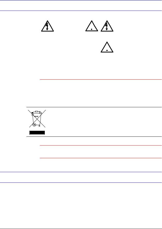
THIS SYMBOL INDICATES |
|
CAUTION |
|
|
|
||
|
|
|
|
|
THAT DANGEROUS VOLTAGE |
|
|
RISK OF |
|
|
|
|
CONSTITUTING A RISK OF |
|
ELECTRICSHOCK |
|
|
|
|
|
|
|
|
|
|
ELECTRIC SHOCK IS |
|
|
DO NOT OPEN |
|
|
|
|
|
|
|
|
|
|
PRESENT WITHIN THE UNIT. |
|
|
|
|
|
|
|
|
|
|
|
|
|||
CAUTION: TO REDUCE THE RISK OF |
|
|
THIS SYMBOL INDICATES |
|||
ELECTRIC SHOCK, DO NOT REMOVE |
|
|
THAT IMPORTANT OPERATING |
|||
|
||||||
THE COVER. NO USER-SERVICEABLE |
|
|
AND MAINTENANCE |
|||
PARTS INSIDE. REFER SERVICING TO |
|
|
INSTRUCTIONS ACCOMPANY |
|||
QUALIFIED SERVICE PERSONNEL. |
|
|
THIS UNIT. |
|||
|
|
|
|
|
|
|
Installation and servicing should be performed only by qualified and experienced technicians to conform to all local codes and to maintain your warranty.
WARNING! |
24 VAC models require the use of CSA Certified/UL Listed |
|
Class 2 power adapters to ensure compliance with |
|
electrical safety standards. Power over Ethernet (PoE) |
|
should meet the IEEE 802.3 af PoE standard. |
|
|
WEEE (Waste Electrical and Electronic Equipment). Correct disposal of this product (applicable in the European Union and other European countries with separate collection systems). This product should be disposed of, at the end of its useful life, as per applicable local laws, regulations, and procedures.
Caution When powering the camera from 24 VAC, a UPS source should be considered to ensure satisfactory performance.
FCC Compliance Statement
Information to the User: This equipment has been tested and found to comply with the limits for a Class B digital device. Pursuant to Part 15B of the FCC Rules, these limits are designed to provide reasonable protection against harmful interference in a residential installation. This equipment generates, uses, and can radiate radio frequency energy and, if not installed and used in accordance with the instruction manual, may cause harmful interference to radio communications. However, there is no guarantee that interference will not occur in a particular installation.
10
HD3MDIP/X Network Camera Reference Guide
If this equipment does cause harmful interference to radio or television reception, which can be determined by turning the equipment off and on, the user is encouraged to try to correct the interference. For example, try reorienting or relocating the receiving antenna, increasing the separation between the equipment and receiver, or connecting the equipment to an outlet on a different circuit.
Caution Changes or modifications not expressly approved by the party responsible for compliance could void the user’s authority to operate the equipment.
This Class B digital apparatus complies with Canadian ICES-003.
Manufacturer’s Declaration of Conformance
North America
The equipment supplied with this guide conforms to UL 60950-1 and CSA C22.2 No. 60950-1.
Europe
The manufacturer declares that the equipment supplied with this guide is compliant with the essential protection requirements of the EMC directive 2004/108/EC and the Low Voltage Directive LVD 20006/95/EC, conforming to the requirements of standards EN 55022 for emissions, EN 50024 for immunity, and EN 60950 for Electrical Equipment safety.
Warranty and Service
Subject to the terms and conditions listed on the Product warranty, during the warranty period Honeywell will repair or replace, at its sole option, free of charge, any defective products returned prepaid.
In the event you have a problem with any Honeywell product, please call Customer
Service at 1.800.796.CCTV for assistance or to request a Return Merchandise
Authorization (RMA) number.
Be sure to have the model number, serial number, and the nature of the problem available for the technical service representative.
Document 800-04132V1 Rev A |
11 |
01/10 |
|

Prior authorization must be obtained for all returns, exchanges, or credits. Items shipped to Honeywell without a clearly identified Return Merchandise Authorization (RMA) number may be refused.
12

1
Introduction
Honeywell HD3MDIP/X color network cameras provide high picture quality remote video surveillance over a network connection. See Table 1-1 for descriptions of the camera models.
Table 1-1 |
Fixed Mini Dome Network Camera Model Numbers |
||
|
|
|
|
Model number |
Description |
|
|
|
|
|
|
HD3MDIP |
|
True Day/Night 720p, 3.3 |
– 12 mm VFAI Lens NTSC |
|
|
|
|
HD3MDIPX |
|
True Day/Night 720p, 3.3 |
– 12 mm VFAI Lens PAL |
|
|
|
|
Features
The Honeywell HD3MDIP/X color network camera features:
•HD, SVGA, VGA, QVGA resolutions
•1/4" color CMOS progressive scan sensor
•Moveable Infrared (IR) cut filter ensures excellent low light performance
•Camera Sabotage Detection
•Video Motion Detection
•MPEG-4 and MJPEG compression
•Dual digital video streams simultaneously, independently configurable
•Remote firmware updates
•Supports both Dynamic and Static IP address assignment
•Multiple levels of password protected remote access prevents unauthorized users from altering system settings
•Includes advanced IP locator software to make system setup easy
•Web server for remote setup of camera video and network parameters
•24 VAC or PoE IEEE 802.3af choice of power inputs
•Supports input and output alarm contacts
•Supports bi-directional audio
•Local video out – aim and focus
Document 800-04132V1 Rev A |
13 |
01/10 |
|

Introduction
14

2
Installation and Setup
This chapter describes how to:
•Mount the camera
•Adjust the camera for the clearest image
•Set up the camera in a network system
Before You Begin
Please carefully read this guide before you install the HD3MDIP/X network camera.
Keep this guide for future reference.
Before installing the camera, Honeywell recommends that you check www.honeywellvideo.com/products/cameras/ to find your camera and download the latest manuals and software updates.
Unpack Everything
Check that the items received match those listed on the order form and packing slip. The
HD3MDIP/X packing box should include, in addition to a Quick Install Guide:
•One fully-assembled HD3MDIP/X camera, including factory-installed BNC connector for local video out aim and focus
•One adapter plate
•One HD3MDIP/X hardware kit that includes mounting screws and screw caps
•One BNC cable for local video out - aim and focus
•One mounting template
•One product warranty
•One CD containing the software and this User Guide
Document 800-04132V1 Rev A |
15 |
01/10 |
|

Installation and Setup
If any parts are missing or damaged, contact the dealer from which you purchased your camera or call Honeywell Customer Service (see Warranty and Service).
Equipment Required
The following tools might help you to complete the installation:
•Drill
•Screwdrivers
•Wire cutters
Overview of Installation Procedure
Note Please familiarize yourself with the installation procedure and complete each step in the exact sequence given.
The initial installation of an HD3MDIP/X camera consists of the following steps:
|
Step |
See … |
|
|
|
1 |
Preparation |
page 18 |
|
|
|
2 |
Connect the wiring. |
page 21 |
|
|
|
|
Mount the camera. |
page 24 |
|
|
|
3 |
Adjust the camera angle, position, and |
page 25 |
|
focus for optimum image. |
|
|
|
|
4 |
Secure the enclosure cover. |
page 27 |
|
|
|
5 |
Program the camera. |
page 55 |
|
|
|
16
HD3MDIP/X Network Camera Reference Guide
Camera Components and Functions
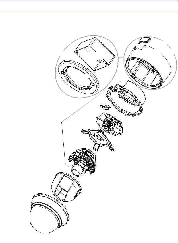
The HD3MDIP/X Network Camera consists of a fully-integrated enclosure with camera and lens. The wiring can be completely concealed to reduce the risk of tampering.
Figure 2-1 |
HD3MDIP/X Camera Components |
|
|
|
|
|
Cover plate |
Flush Mount |
Back box |
Surface Mount |
|
|
|||
|
|
(not supplied) |
|
|
|
|
Skirt |
|
Adapter plate |
|
|
|
|
|
Base |
Camera |
|
|
|
|
|
|
Interface board |
|
|
Gimbal base |
|
|
|
Gimbal assembly |
|
|
|
Turret (bubble insert) |
|
|
Bubble |
|
|
Document 800-04132V1 Rev A |
|
|
17 |
01/10 |
|
|
|
Installation and Setup
Camera Installation
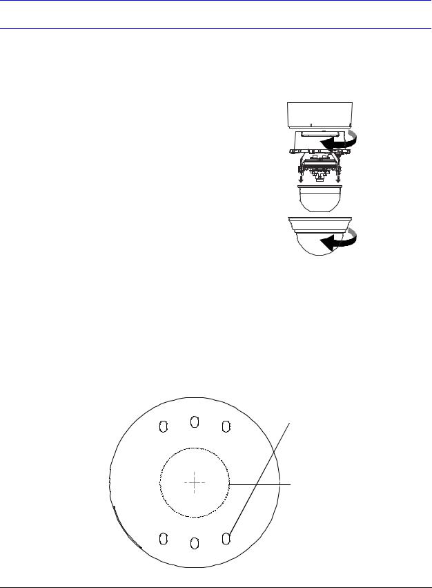
Preparing the Camera
1.Rotate the bubble counterclockwise until it disconnects.
2.Pull the turret to remove it.
3.Rotate the camera counterclockwise until it disconnects from the skirt.
4.Set aside the bubble, turret, and camera.
Skirt
 Camera
Turret
Bubble
Preparing the Mounting Surface
1.Mark the mounting surface for screw holes and wire access hole.
•Use the mounting template if you are surface mounting your camera. See
Mounting Template on page 65
•Use the flush mount adapter plate as a template if you are flush mounting your camera.
Figure 2-2 Mounting Template
Drill these holes for the mounting screws.
Cut this hole, then pull the power, audio, and alarm wires through it.
18

HD3MDIP/X Network Camera Reference Guide
2.Pre-drill the holes as indicated on the template, using the recommended hole size for the screws being used.
Note Other fasteners (preferably stainless steel) can be used, provided they are not larger than the screw holes on the mounting template.
Connecting the Wires
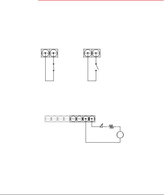
Connecting Audio and Alarms
1.Pull the wires through the ceiling or wall hole until you have at least 4 inches of wire.
2.Remove the green connector strip (see Figure 2-6 on page 22) from the camera base and make all the necessary alarm and audio connections.
3.Connect a twisted pair (UTP) cable from each peripheral alarm contact to each alarm input on the terminal block.
Figure 2-3 Audio and Alarm PINs
Power |
1 |
2 |
3 |
4 |
5 |
6 |
7 |
8 |
Table 2-1 Audio and Alarm Connector PIN Definitions
PIN Definition
1 Audio In +
2Audio In -
3 Audio Out +
4 Audio Out -
5 Alarm In +
6Alarm In -
7 Alarm Out +
8Alarm Out -
Connecting Audio
The network camera supports bi-directional audio. There are two supported voice band channels that function in full duplex mode. The camera can transmit audio from the camera to the client (PC) using any audio source that provides an industry standard line level input (see the terminal strip as depicted in Figure 2-6). The camera can also receive audio from
Document 800-04132V1 Rev A |
19 |
01/10 |
|
Installation and Setup
the client (PC) and provide an industry standard line level output suitable to connect to audio devices. Audio input and output have 600 Ohm impedance. See Audio Settings on page 63 to configure audio options.
Connecting Alarms
WARNING! |
Do not exceed the maximum rating of 12 VDC, 0.5 A on alarm |
|
output connections. |
|
|
The HD3MDIP/X network camera has one alarm input and one alarm output. Connect mechanical or electrical switches to the alarm input connection to allow event-triggered recording. When alarm inputs are configured, the HD3MDIP/X triggers an alarm only when the normal alarm state (open or closed) changes.
Figure 2-4 Normal Alarm States
Normally closed |
Normally opened |
See Alarm Settings on page 62 to configure the alarm inputs.
Connect external devices such as sirens or flashing lights to the alarm output connector to signal an activated alarm to camera users.
Figure 2-5 Alarm Connection
Audio |
Alarm |
In |
Out |
− +
+
−
The alarm output can be configured to provide normally open or normally closed contacts (see Alarm Settings on page 62 to configure the alarm output). Contacts will be rated for 12 VDC @ 0.5 A.
4.Pull the cables through the back or side entries of the camera skirt, then connect the green connector strip to the camera assembly. You might have to remove the cover plate for flush mount.
20
HD3MDIP/X Network Camera Reference Guide
Connecting Power
WARNING! The use of a CSA Certified/UL Listed Class 2 power supply is required to ensure compliance with electrical safety standards.
Note Check the power source from the external power supply before applying power to the camera.
1.Connect the appropriate power supply for your installation:
•24 VAC power supply (proceed to step 2) or
•Power over Ethernet (IEEE 802.3af) 48 VDC power supply
Note If you are using PoE (802.3af), power will automatically be supplied to the camera through the network cable.
2.Connect to the power supply (see Figure 2-6 on page 22).
3.Plug the power supply into an appropriate power source. The LED on the RJ45 jack illuminates when the camera receives power. If it does not illuminate, check the terminal block connections and the power source.
Note To ensure satisfactory performance, it is recommended that you use a UPS source when connecting the camera to a 24 VAC power source.
Document 800-04132V1 Rev A |
21 |
01/10 |
|

Installation and Setup
Figure 2-6 Camera and Cables
24 VAC power
Figure 2-7 Wiring Connection Shown on Board
Factory reset button
Local video out connector  (for aim and focus)
RJ45 Ethernet Connector
(see Connecting to a Network via an RJ-45 Ethernet Connector, page 23)
RJ45 Ethernet network connection (using 10Base T
or 100Base TX cable). See
Connecting to a Network via an RJ-45 Ethernet Connector, page 23)
Also for Power over Ethernet (PoE 802.3af)
Connector Strip
Audio: Input/Output
Alarm: Input/Output
(see Connecting Alarms, page 20)
22

HD3MDIP/X Network Camera Reference Guide
Caution Installation must be performed by a qualified electrician. The power wire size for the distance and the number of cameras must be determined to maintain 24 VAC at each camera.
Connecting to a Video Monitor
The local video out (see Figure 2-7) is available as a test output and should be used as needed during installation to position, aim, and focus the camera. Use the provided BNC connector to connect the video from the camera to the video input connector on your video monitor.
Connecting to a Network via an RJ-45 Ethernet Connector
The main video connection for your network camera will be made through your Ethernet network connection. Connect the Ethernet connector on your camera to your network using an Ethernet (10Base-T, 100Base-TX) cable.
Note You can connect your camera to a network or use any type of CAT5 cable to connect it directly to a PC or laptop.
Document 800-04132V1 Rev A |
23 |
01/10 |
|
Installation and Setup
Mounting the Camera
Surface Mount
1.Secure the skirt to the ceiling or wall using the appropriate screws (supplied).
2.Connect the wires (see Connecting the Wires on page 19).
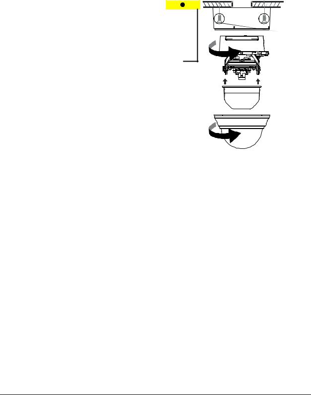
3.Rotate and align the camera assembly yellow label with the skirt yellow label.
4.Secure the camera assembly to the skirt by pushing it into the skirt, then twisting it clockwise until it clicks securely in place.
5.Secure the camera assembly to the skirt by twisting it clockwise until it clicks securely in place.
Skirt
Screws (supplied)
Camera assembly
Turret
Bubble
6.Adjust the camera’s field of view (see
Adjusting the Camera FOV (Field of View) on page 25).
7.Install the turret by clicking it into place.
8.Install the bubble by placing it on the camera with the tabs to the left of the slots, then turning it clockwise until the tabs click securely into place.
24
Loading...