


fM O D U F L E X ®
Montageanleitung Fitting instructions FTS 015 / FTSB 015
2-Phasen- Frostschutzsteuerung mit Begrenzerkontakt und Prioritätsauswahl
Funktionsweise
1.Phase 10°–5 °C: Heizventil
stetig öffnen mit Ausgangssignal 0–10 V
2.Phase
bei 4 °C: Anlage abschalten mit Mikroschalter (potentialfrei)
2-phase-frost protection controller with limiter contact and integrated priority selection
Mode of operation
1.Phase 10°–5 °C:
open heating valve continuously, with output signal
0–10 V
2.Phase
at 4 °C:
switch off unit with microswitch (potential-free)
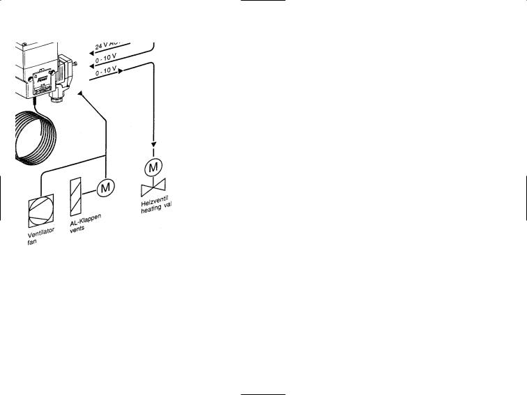
Funktionsweise
Die Frostschutzsteuerung erzeugt bei fallender Temperatur ein stetiges Ausgangssignal von 0–10 V. Bei weiter fallender Temperatur wird ein Begrenzerkontakt (einpolig umschaltend) betätigt.
Wird das Ausgangssignal des Reglers (Y-Signal) durch die Frostschutzsteuerung hindurchgeschleift, findet eine Maximalauswahl der beiden Signale statt. Ist das Y-Signal vom Regler größer als das Ausgangssignal der Frostschutzsteuerung, bestimmt der Regler die Stellung des Heizventils (Normalbetrieb). Ist das Ausgangssignal der Frostschutzsteuerung größer als das Y-Signal des Reglers (Frostgefahr), bestimmt die Frostschutzsteuerung die Stellung des Heizventils, solange vom Sensor „Frostgefahr“ signalisiert wird. Ist die Frostgefahr beseitigt, übernimmt automatisch wieder der Regler die Ansteuerung des Heizventils.
Der über die gesamte Länge wirksame Sensor ist selbstüberwachend, d. h. bei Bruch oder Beschädigung des Kapillarrohrs, wird „Frostgefahr“ signalisiert.
Wird das Signal des Reglers nicht durchgeschleift, gibt der FTS das Signal der Frostschutzsteuerung aus.
The frost protection generates with falling temperature a constant output signal of 0–10 V. If the temperature drops further, a limiter contact (sin- gle-pole changeover contact) is actuated.
If the output signal of the controller (Y-signal) is looped through the frost protection, a maximum selection of the two signals takes place. If the Y-signal from the controller is larger than the output signal of the frost protection, the controller determines the position of the heating valve (normal operation). If the output signal of the frost protection is larger than the Y-signal of the controller (risk of frost) then the frost protection determines the position of the heating valve as long a “Risk of frost” is signaled by the sensor. Once the risk of frost is removed, the controller automatically takes over control of the heating valve again.
The sensor acting over the entire length is self-monitoring, i.e. in the case of breakage or damage of the capillary tube, “Risk of frost” is signaled.
If the signal of the controller is not looped through, then the FTS outputs the frost control signal.
2
Maximalauswahl zwischen den Signalen des Reglers und der Frostschutzsteuerung. Das größere der beiden Signale steht an Klemme 3 zur Verfügung.
Maximum selection between the signals of controller and frost protection. The higher of both signals is available at terminal 3.
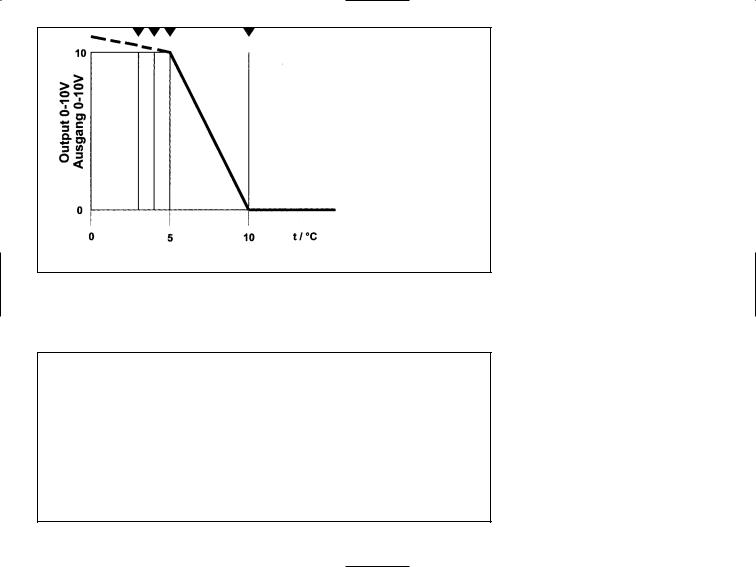
Arbeitsbereich
A = 10 °C
Beginn des Arbeitsbereiches (bei fallender Temperatur)
B = 5 °C
Ende des stetigen Bereichs
C = 4 °C
Schaltpunkt des Umschaltkontakts
D = 3 °C
Mechanischer Anschlag der
Einstellspindel
Bei Bedarf können mehrere Frostschutzsteuerungen hintereinander geschaltet werden (Kaskadierung). Das größte aller Signale wird dem Stellglied zugeführt.
Working range
A = 10 °C
Start of the working range (with decreasing temperature)
B = 5 °C
End of the continuous range
C = 4 °C
Switching point of switch over contact
D = 3 °C
Mechanical stop of the setting spindle
If required, several frost protections can be connected in series (cascade connection). The highest signal will be injected to the actuator.
3
 Loading...