


Wireless Room Thermostat
Installation and Operation
Drahtloser Raumthermostat
Montage und Bedienung
Thermostat d’ambiance sans-fil pré-configuré
Installation et Utilisation
Draadloze Kamerthermostaat
Installatie en gebruik
Bezprzewodowy Termostat
Pomieszczeniowy
Instrukcja Montażu i Obsługi
Termostat de cameră fără fir
Instalare şi Operare
ENGLISH 5
DEUTSCH 13
FRANÇAIS 21
NEDERLANDS 29
POLSKI 37
ROMÂN 45
General safety instructions
Contents |
|
|
1. |
General safety instructions.................................... |
5 |
1.1. |
Commissioning the relay module HC60NG........... |
5 |
2. |
Overview ............................................................... |
6 |
2.1. |
Pre configured kit Y6630D1007............................. |
6 |
2.2. |
Singly provided devices......................................... |
6 |
3. |
Installation ............................................................. |
6 |
3.1. |
Installation relay module HC60NG ........................ |
6 |
3.1.1. |
Connections for R6660D and HC60NG................. |
7 |
3.2. |
Installation room unit HCW 80............................... |
8 |
4. |
Checking ............................................................... |
9 |
4.1. |
System check ........................................................ |
9 |
4.2. |
Radio transmission check ..................................... |
9 |
5. |
Teach-in (singly provided devices only) ................ |
9 |
5.1. |
Assignment to the relay module HC60NG............. |
9 |
5.2. |
Failed teach-in....................................................... |
9 |
6. |
Communication loss .............................................. |
9 |
7. |
Factory reset of relay module HC60NG ................ |
9 |
8. |
Particular features of the room unit HCW 80....... |
10 |
8.1. |
Operation ............................................................ |
10 |
8.2. |
Limiting the adjustment range ............................. |
10 |
8.3. |
Fixed control parameters..................................... |
10 |
9. |
Changing batteries .............................................. |
10 |
10. |
Appendix ............................................................. |
11 |
10.1. |
Help with problems.............................................. |
11 |
10.2. |
Specifications HCW 80........................................ |
11 |
10.3. |
Specifications HC60NG....................................... |
11 |
10.4.Device and function definition in accordance
with EN 60730-1.................................................. |
11 |
10.5.WEEE directive 2002/96/EC – Waste Electrical
and Electronic Equipment directive ..................... |
11 |
1.General safety
instructions
1.1.Commissioning the relay module HC60NG
DANGER |
Danger to life due to electric shock! |
|
Contacts that are open are live. |
|
► Ensure that the device is de- |
|
energised. |
|
► Have all the work carried out by |
|
authorised qualified personnel. |
|
► Observe the valid local regulations |
|
during the installation. |
|
|
|
|
WARNING |
Insufficient data transfer! |
|
Interference of the relay module |
|
HC60NG in the device due to metallic |
|
objects or further frequency devices. |
|
► Mount the device with a distance of at |
|
least 30 cm to metallic objects such |
|
as wall boxes or boiler housings |
|
according to the DECT standard, etc. |
|
► Do not mount on metal wall boxes. |
|
|
|
|
WARNING |
Damage to the device! |
|
Short-circuiting due to humidity and |
|
moisture. |
|
► Mount the device at a site that is |
|
protected against humidity and |
|
moisture. |
|
|
|
|
WARNING |
Damage to exposed components! |
|
Destruction of the electronic |
|
components due to electrostatic |
|
discharges. |
|
► Do not touch the components. |
|
► Touch an earthed piece of metal to |
|
discharge static electricity from your |
|
body. |
|
|
5

Overview
2.Overview
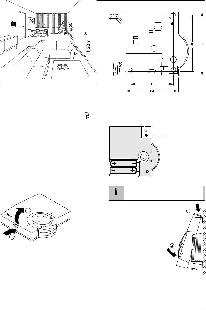
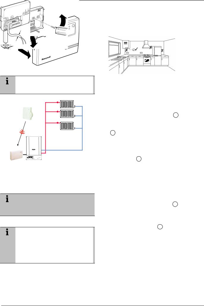
The room unit HCW 80 is used for intelligent room temperature control in combination with the relay module HC60NG. It can be used to control gas and oil boilers, a variety of valves and actuators or electrical heating systems. No wiring to the room unit HCW 80 is required.
Because of the simple HCW 80 analogue user interface with absolute set point temperature scale, the room set point temperature can be easily adjusted.
The room unit and the relay module provide reliable RF communication technology on 868 MHz frequency.
The HCW 80 and HC60NG are already teachedin (bounded). They are provided as pre configured kit for fast installation (plug and play).
Zone 1
Wireless Room Thermostat |
HCW80 |
Example radiator control |
Relay module |
HC60NG |
Boiler |
Fig. 1: Application of the wireless room thermostat
2.1.Pre configured kit Y6630D1007
•1 HCW 80 (room unit)
•1 HC60NG (R6660D1009, relay module)
•2 AA batteries, 1.5 V, type LR6
The kit Y6630D1007 is provided pre-bound.
The room unit HCW 80 is already assigned to the relay module HC60NG. The teach-in is not required in this kit.
2.2.Singly provided devices
Singly provided devices must be teached-in as described in section 5 “Teach-in (singly provided devices only)”.
Teach-in means the HCW 80 and HC60NG must be RF bound for communication.
3.Installation
3.1.Installation relay module HC60NG
Fig. 2: Positioning the relay module HC60NG
►Follow the installation diagrams to install and connect the power supply to the relay module HC60NG.
1
1
2
Fig. 3: Opening the housing cover
1
2
Fig. 4: Removing the terminal covers
> 7 mm Æ
< 7 mm Æ
Fig. 5: Connecting the relay module to the power supply
6

Installation
max. 2.5 mm2
Fig. 6: Wiring the terminal
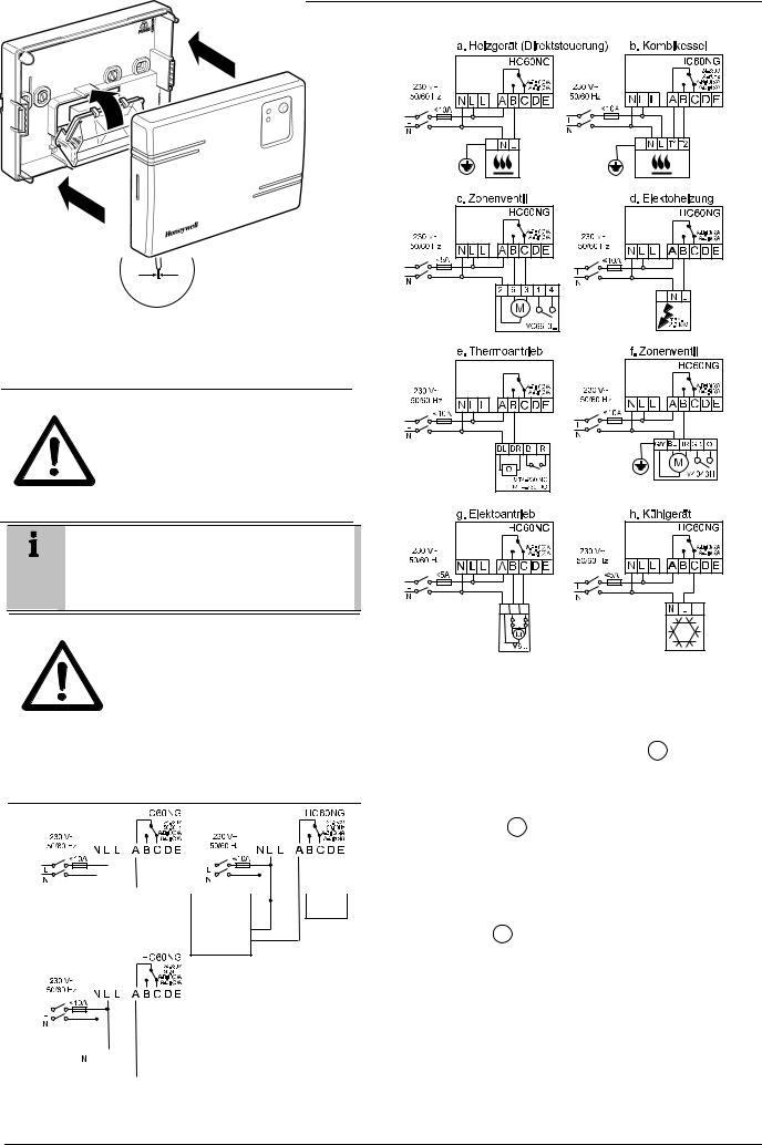
3.1.1.Connections for HC60NG (R6660D1009)
CAUTION |
Incorrect wiring! |
|
► Install in accordance with local wiring |
|
regulations. |
|
► Observe ambient temperature and |
|
current limits (see HC60NG wiring |
|
label). |
The green LED on the receiver indicates demand from the thermostat NOT that the heating will be on, this depends on the programmer settings.
CAUTION |
Incorrect wiring! |
|
Honeywell accepts no liability for any |
|
loss or damage arising from any errors |
|
or omissions that may be inadvertently |
|
contained within this sketch. This is a |
|
proposal sketch only, not a certified |
|
wiring diagram. |
|
► This diagram must be read in |
|
conjunction with any boiler or cylinder |
|
manufacturers instructions. |
|
|
|
|
|
|
|
|
|
|
|
|
|
|
|
|
|
|
|
|
|
|
|
|
|
|
|
|
|
|
|
|
|
|
|
|
|
|
|
|
|
|
|
|
|
|
|
|
|
|
|
|
|
|
|
|
|
|
|
|
|
|
|
|
|
|
|
|
|
|
|
|
|
|
|
|
|
|
|
|
|
|
|
|
|
|
|
|
|
|
|
|
|
|
|
|
|
|
|
|
|
|
|
|
|
|
|
|
|
|
|
|
|
|
|
|
|
|
|
|
|
|
|
|
|
|
|
|
|
|
|
|
|
|
|
|
|
|
|
|
|
|
|
|
|
|
To Combi |
|
|
Timer L |
|
|
|
|
|
|
|
|
|
|
|
|
|
|||||||
|
|
|
|
|
|
|
|
|
|
|
|
|
|
|
To |
||||||||||||
|
|
|
|
|
|
|
|
|
|
|
|
|
|
|
|||||||||||||
|
|
|
|
|
|
|
|
|
|
|
|
|
|
N |
|
|
|
|
|
|
|
|
|
Combi |
|||
|
|
|
|
|
|
|
|
|
|
|
|
|
|
|
|
|
|
|
|
|
|
|
|||||
|
|
|
|
|
|
|
|
|
|
|
|
|
|
|
|
|
|
|
|
|
|
|
|
|
|
|
|
LIVE IN
ON
Fig. 8: Wiring diagram for HC60NG
2
1
2
Fig. 9: Closing the terminal and housing cover
Fig. 7: Wiring diagram for HC60NG
7
Installation
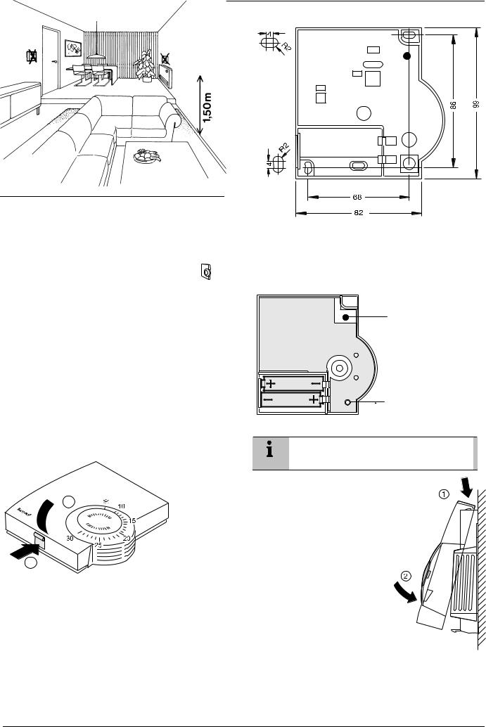
3.2.Installation room unit HCW 80
WARNING Insufficient data transfer!
Interference of the radio receiver in the device due to metallic objects or further radio devices.
► Ensure there is sufficient distance to metallic objects.
►Mount the device with a distance of at least 1 m to radio devices such as radio headphones, cordless phones according to the DECT standard, etc.
►Select another installation site if the radio interference cannot be corrected.
Fig. 10: Positioning the room unit HCW 80
►Place the room unit HCW 80 at the installation site.
►Remove the housing cover of the room unit HCW 80 (see Fig. 11: Removing the housing cover).
Fig. 12: Drilling scheme (measurements in mm)
►Drill the holes.
►Screw on the room unit.
►Insert the supplied AA batteries with the correct battery polarity (see Fig. 13: Battery polarity and send button).
Red LED
Send button
Fig. 13: Battery polarity and send button
The batteries have to be replaced when the red LED at the room unit HCW 80 flashes (see section 9 “Changing batteries”).
2  ► Place the housing cover in position above and snap it down
  (see Fig. 14).
1
Fig. 11: Removing the housing cover
► Mark the drill holes according to the drilling template (see Fig. 12).
Fig. 14: Placing housing cover in position
8
Checking
4.Checking
4.1.System check
►Adjust the set point of the room unit HCW 80 to 30 °C.
If the room temperature is >30 °C the relay module HC60NG is switched on.
►Change the set point of the room unit HCW 80 to 5 °C.
If the room temperature is <5 °C the relay module HC60NG is switched OFF.
4.2.Radio transmission check
The room unit HCW 80 can send a test signal to the assigned relay module HC60NG in order to test the signal strength.
►Keep the teach-in button of the HCW 80 pressed for at least 15 sec until the red LED of the HCW 80 is OFF.
The HCW 80 is now in test mode and sends a test signal every 5 sec.
The LED of the HCW 80 flashes briefly at every test signal the HCW 80 is sending.
The field strength is indicated by flashing of the red LED of the HC60NG (1 = sufficient, 5 = strong).
►If the wireless communication is not successful optimise the placement of the HCW 80.
The test mode is terminated automatically after 5 min. The test mode can also be terminated by removing the batteries or by pressing the teachin button.
5.Teach-in (singly provided
devices only)
The teach-in operation is required if the relay module HC60NG and the room unit HCW 80 are not pre-bound e.g. new single devices or product replacement.
5.1.Assignment to the relay module
HC60NG
After the power up of the relay module HC60NG the red LED will start to flash at 0.1 sec ON / 0.9 sec OFF.
If this is not the case set the HC60NG into the reset mode see section 7 “Factory reset of relay module HC60NG”.
►Press and hold the teach-in button of the HC60NG for 5 sec to enter into the teach-in mode.
The red LED flashing at 0.5 sec ON / 0.5 sec OFF confirms the teach-in mode has been entered.
►Press the teach-in button of the HCW 80 to send the binding signal to the HC60NG.
The red LED of the HC60NG is switched OFF to confirm a successful teach-in operation.
The teach-in mode is terminated automatically after 5 min.
5.2.Failed teach-in
If the teach-in has failed:
►See section 5.1 “Assignment to the relay module HC60NG”.
►Improve the data transfer.
Improving the data transfer
►When selecting the operating site of each device ensure that the distance to radio devices such as radio headphones, cordless phones, etc. according to the DECT standard amounts to at least 1 m.
►Do not install the devices over metallic wall connecting sockets and at least 30 cm away from the cover of the heat generator.
►Correct the installation site of the room unit HCW 80 if necessary.
6.Communication loss
When the RF communication is lost for a period of 1 h, the red LED of the relay module HC60NG is ON to indicate that no RF messages have been received during the last hour. When RF communication is re-established the relay module HC60NG will automatically return to normal operation mode.
See chapter 10.1 “Help with problems” for possible cause and problem solving.
7.Factory reset of relay
module HC60NG
►Keep the button of the HC60NG pressed for at least 15 sec.
The resetting was successful when the red LED flashes rapidly (1/9 ON/OFF).
After the factory reset the HC60NG looses the communication with the HCW 80.
See section 5 “Teach-in (singly provided devices only)” for new teach-in.
9
Particular features of the room unit HCW 80
8.Particular features of the room unit HCW 80
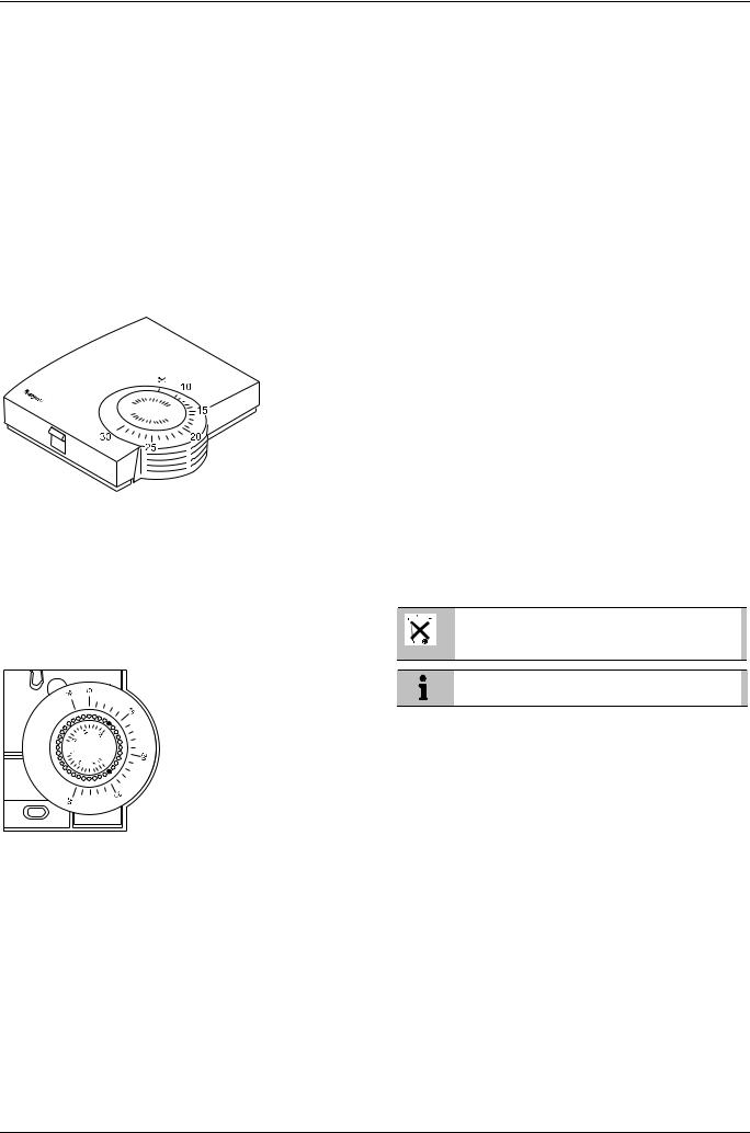
8.1.Operation
The room set point temperature can be set easily at the set point adjuster by means of an adjustment dial. The room set point range is from 10 °C to 30 °C including the frost protection setting  (5 °C).
The HCW 80 simulates a mechanical thermostat by LED indication as follows:
The red LED at the HCW 80 will be switched ON for 4 sec if the deviation between the set point and the room temperature is >1 °C. If the deviation is <1 °C the red LED is flashing for 4 sec. Respectively the relay module HC60NG will be switched ON or OFF.
►Place the two small pins into the holes of the adjustment dial in order to limit the adjustment range (see Fig. 16). Orientate yourself on the basis of the inner scale:
In Fig. 16, the pins are inserted so that the adjustment dial can only be adjusted in the range of 19 °C to frost protection  (lower limit) and 19 °C to 30 °C (higher limit) around the value 19 °C.
►Turn the adjustment dial clockwise until it stops.
►Check whether the adjustment dial is in the position shown in Fig. 15.
►If appropriate, put the adjustment back in, rotated by 180° until it has the position shown.
►Turn the adjustment dial to position 19.
►Place the housing cover in position above and snap it down (see Fig. 14, Page 8).
Fig. 15: Room unit HCW 80 (settings on the scale in °C)
►Select the desired room temperature set point at the adjustment dial (see Fig. 15).
8.2.Limiting the adjustment range
You can limit the adjustment range that can be used at the adjustment dial.
► Remove the housing cover (see Fig. 11, Page 8).
8.3.Fixed control parameters
The following parameters will be used for the control:
Parameter |
Factory setting |
Remark |
Minimum ON |
1 minute |
Minimum power up |
time |
|
time within the cycle |
Cycle rate |
6 cycles per hour |
Pulse width |
|
|
modulation per hour |
9.Changing batteries
Change the batteries if the red LED of the room unit HCW 80 flashes and the device is not in test mode.
►Remove the housing cover of the HCW 80 (see Fig. 11, Page 8).
►Remove the batteries.
Dispose of the batteries according to the local statutory requirements and not with the domestic refuse.
Always replace both batteries together. Only use
1.5V batteries of the type LR06, AA.
►Insert the batteries with the correct polarity into the battery compartment (see Fig. 13, Page 8).
►Place the housing cover on at the top and latch it in downwards (see Fig. 14, Page 8).
Fig. 16: Limiting the adjustment range
10
Appendix
10. Appendix
RF
10.1. Help with problems |
|||
|
|
|
|
Problem |
Cause |
Remedy |
|
Teach-in failed |
Batteries |
► Insert the batteries |
|
|
inserted |
correctly. |
|
|
incorrectly |
||
|
|
||
|
Radio |
► Eliminate interference |
|
|
connection |
||
|
failure |
sources (metal, wireless |
|
|
devices). |
||
|
|
||
|
|
► Correct installation site. |
|
|
|
► Repeat the teach-in. |
|
|
|
|
|
HC60NG does |
HC60NG |
► Reset HC60NG. |
|
not react to set |
and |
► Follow the teach-in |
|
point changes |
HCW 80 not |
||
on HCW 80 |
teached-in |
procedure as described |
|
in section 5. |
|||
|
|
||
|
|
|
|
After teach-in |
Teach-in |
► Repeat the teach-in. |
|
red LED is on |
procedure |
|
|
and green LED |
incorrect/ |
|
|
is flashing once |
incomplete |
|
|
every 3 sec |
Position of |
► Repeat the teach-in |
|
|
HCW 80 |
keeping approx. 1 m |
|
|
incorrect |
||
|
distance between |
||
|
|
||
|
|
HCW 80 and HC60NG. |
|
|
|
|
|
Red LED of the |
Communi- |
► Relocate the HCW 80 |
|
HC60NG is on |
cation loss |
(see section 3.2). |
|
|
RF signal |
|
|
|
blocked |
|
|
|
Batteries of |
► Replace batteries in |
|
|
HCW 80 |
HCW 80 |
|
|
exhausted |
||
|
(see section 9). |
||
|
|
||
|
|
|
|
|
HC60NG |
► Follow the teach-in |
|
|
and |
procedure as described |
|
|
HCW 80 not |
||
|
in section 5. |
||
|
teached-in |
||
|
|
||
10.2. Specifications HCW 80
Batteries |
1.5 V, type LR06, AA |
Frequency |
868.3 MHz (transmitter) |
Operating temperature |
0 °C to 50 °C |
Storage temperature |
–20 °C to 70 °C |
Humidity |
5 % to 90 % relative humidity |
IP class |
30 |
10.3. Specifications HC60NG
Electrical
Receiver power supply |
230 V AC (+10 %, –15 %), 50 Hz |
Switch type |
SPDT potential free |
Output rating |
24–230 V AC, 10 A resistive, |
|
3 A inductive, 0.6 p.f. |
Wire access |
From the rear (wall box mounting), |
(receiver only) |
right an bottom |
RF operation band
RF communication range
RF communication technology
Blocking immunity
RF binding method
ISM (868.0–868.6) MHz, 1 % duty cycle
30 m in a residential building environment
Short, high rate transmissions to minimise air time and avoid collisions
Receiver class 2 (ETSI EN300 220-1 version 1.3.1)
Factory pre-bound with the room unit HCW 80 (kit Y6630D1007 only)
Environmental & Standard
Operating temperature |
0 to 40 °C when relay load <8 A |
|
0 to 30 °C when relay load >8 A |
Shipping & storage |
–20 to 55 °C |
temperature |
|
Humidity |
Humidity range 0 to 90 % rh, |
|
non-condensing |
IP class |
30 |
Meeting the following |
EN 60730-1 (1995), EN 55014-1 |
standards |
(1997), EN 55014-2 (1996), ETSI |
|
EN 300 220-3 (2000), ETSI |
|
EN 301 489-3 (2000) |
10.4. Device and function definition in accordance with EN 60730-1
•Purpose of the device is temperature controlling
•Device fulfills protection class 2
•Independently installable electronic control system with fixed installation
•Type of action is type 1.8
•Temperature of ball thrust hardness test for housing components 75 °C and for live parts such as, for example, terminals 125 °C
•EMC emitted interference test at 230 V , 50 HZ maximum
•Pollution degree is 2
•Rated voltage is 4000 V (corresponding to overvoltage category III)
•Software class is A
10.5.WEEE directive 2002/96/EC – Waste Electrical and Electronic Equipment directive
► At the end of the product life dispose of the packaging and product in a corresponding recycling centre.
► Do not dispose of the unit with the usual domestic refuse.
► Do not burn the product.
11

Allgemeine Sicherheitshinweise
Inhaltsverzeichnis
1. |
Allgemeine Sicherheitshinweise .......................... |
13 |
1.1.Inbetriebnahme des Relaismoduls HC60NG
|
(R6660D1009)..................................................... |
13 |
2. |
Übersicht ............................................................. |
14 |
2.1. |
Vorkonfiguriertes Kit Y6630D1007 ...................... |
14 |
2.2. |
Einzeln gelieferte Geräte..................................... |
14 |
3. |
Montage .............................................................. |
14 |
3.1.Montage des Relaismoduls HC60NG
|
(R6660D1009)..................................................... |
14 |
3.1.1. |
Anschlüsse für R6660D und HC60NG ................ |
15 |
3.2. |
Montage des Raumgeräts HCW 80..................... |
16 |
4. |
Überprüfung ........................................................ |
17 |
4.1. |
Systemprüfung .................................................... |
17 |
4.2. |
Prüfung der Funkübertragung ............................. |
17 |
5. |
Teach-in (nur bei einzeln gelieferten Geräten) .... |
17 |
5.1.Zuordnung zum Relaismodul HC60NG
|
(R6660D1009)..................................................... |
17 |
5.2. |
Misslungenes Teach-in ....................................... |
17 |
6. |
Kommunikationsausfall ....................................... |
17 |
7.Zurücksetzen des Relaismoduls HC60NG
(R6660D1009) auf die Werkseinstellungen......... |
17 |
8.Besondere Merkmale des Raumgeräts HCW 80. 18
8.1. |
Bedienung ........................................................... |
18 |
8.2. |
Verstellbereich begrenzen................................... |
18 |
8.3. |
Feste Regelungsparameter................................. |
18 |
9. |
Batteriewechsel ................................................... |
18 |
10. |
Anhang................................................................ |
19 |
10.1. |
Hilfe im Problemfall ............................................. |
19 |
10.2. |
Technische Daten HCW 80................................. |
19 |
10.3. |
Technische Daten HC60NG (R6660D1009)........ |
19 |
10.4.Geräteund Funktionsdefinitionen gemäß
EN 60730-1 ......................................................... |
19 |
10.5.WEEE-Richtlinie 2002/96/EG – Elektround
Elektronikgesetz .................................................. |
19 |
1.Allgemeine Sicherheits-
hinweise
1.1.Inbetriebnahme des Relaismoduls HC60NG (R6660D1009)
GEFAHR |
Lebensgefahr durch Stromschlag! |
|
Offenliegende Kontakte mit Netzspan- |
|
nung. |
|
► Stellen Sie sicher, dass am Gerät |
|
keine Spannung anliegt. |
|
► Lassen Sie alle Arbeiten von autori- |
|
siertem Fachpersonal ausführen. |
|
► Beachten Sie bei der Installation die |
|
gültigen Vorschriften. |
|
|
|
|
WARNUNG |
Unzureichende Datenübertragung! |
|
Störung des Relaismoduls HC60NG |
|
(R6660D1009) im Gerät durch metalli- |
|
sche Gegenstände oder weitere Funk- |
|
geräte. |
|
► Montieren Sie das Gerät mit mindes- |
|
tens 30 cm Abstand zu Metallge- |
|
genständen wie Wandkästen oder |
|
Boilergehäusen, schnurlosen Telefo- |
|
nen nach DECT-Standard etc. |
|
► Montieren Sie das Gerät nicht auf |
|
Wandkästen aus Metall. |
|
|
|
|
WARNUNG |
Beschädigung des Geräts! |
|
Kurzschluss durch Feuchtigkeit und |
|
Nässe. |
|
► Montieren Sie das Gerät an einem |
|
vor Feuchtigkeit und Nässe ge- |
|
schützten Ort. |
|
|
|
|
WARNUNG |
Beschädigung von offen liegenden |
|
Bauteilen! |
|
Zerstörung der elektronischen Bauteile |
|
durch elektrostatische Entladungen. |
|
► Berühren Sie die Bauteile nicht. |
|
► Geerdetes Metallteil berühren, um |
|
sich zu entladen. |
|
|
13
Übersicht
2.Übersicht
Das Raumgerät HCW 80 wird in Kombination mit dem Relaismodul HC60NG (R6660D1009) zur intelligenten Raumtemperaturregelung verwendet. Es kann zur Regelung von Gasund Öl-Kesseln, von verschiedenen Ventilen und Stellantrieben oder von elektrischen Heizsystemen eingesetzt werden. Es ist keine Verdrahtung mit dem Raumgerät HCW 80 erforderlich.
Aufgrund der unkomplizierten, analogen Benutzeroberfläche des HCW 80 mit einer Temperatursollwertskala, die Absolutwerte angibt, kann der Raumtemperatursollwert sehr einfach eingestellt werden.
Das Raumgerät und das Relaismodul arbeiten mit zuverlässiger Funkkommunikation auf 868 MHz.
Das Teach-in (Abstimmung) wurde für HCW 80 und HC60NG (R6660D1009) bereits durchgeführt. Die Geräte werden als vorkonfiguriertes Kit für die Schnellmontage (Plug & Play) geliefert.
Zone 1
Raumgerät |
HCW80 |
Beispiel Heizungsregelung |
Relais modul |
HC60NG |
Boiler |
Abb. 1: Anwendung des drahtlosen Raumthermostats
2.1.Vorkonfiguriertes Kit Y6630D1007
•1 HCW 80 (Raumgerät)
•1 HC60NG (R6660D1009, Relaismodul)
•2 Mignon-Batterien, 1,5 V, Typ LR6
Für das Kit Y6630D1007 wird die Abstimmung bereits vor der Auslieferung durchgeführt. Damit ist das Raumgerät HCW 80 bereits dem Relaismodul HC60NG (R6660D1009) zugeordnet. Bei diesem Kit ist also kein Teach-in erforderlich.
2.2.Einzeln gelieferte Geräte
Für einzeln gelieferte Geräte muss das Teach-in wie in Abschnitt 5 „Teach-in (nur bei einzeln gelieferten Geräten)“ beschrieben durchgeführt werden.
Teach-in bedeutet, dass für HCW 80 und HC60NG (R6660D1009) zur erfolgreichen Kommunikation eine Abstimmung auf ihre Frequenz durchgeführt werden muss.
3.Montage
3.1.Montage des Relaismoduls HC60NG (R6660D1009)
Abb. 2: Relaismodul HC60NG (R6660D1009) positionieren
►Für Montage und Anschluss der Stromversorgung an das Relaismodul HC60NG (R6660D1009) folgen Sie den Montageschemata.
1
1
2
Abb. 3: Gehäusedeckel öffnen
1
2
Abb. 4: Klemmenabdeckungen abnehmen
> 7 mm Æ
< 7 mm Æ
Abb. 5: Relaismodul an die Stromversorgung anschließen
14
Montage
max. 2.5 mm2
Abb. 6: Klemmen verdrahten
3.1.1.Anschlüsse für HC60NG (R6660D1009)
VORSICHT Fehlerhafte Verdrahtung!
►Nehmen Sie die Verdrahtung gemäß den gültigen Vorschriften vor.
►Beachten Sie die Umgebungstempe-
ratur und die Stromgrenzwerte (siehe Anschlussetikett des HC60NG (R6660D1009)).
Die grüne LED auf dem Empfänger zeigt lediglich an, dass eine Anforderung vom Thermostaten vorliegt, NICHT, dass die Heizung eingeschaltet ist. Dies hängt von den Einstellungen am Programmierer ab.
VORSICHT Fehlerhafte Verdrahtung!
Honeywell haftet nicht für Schäden, die auf versehentliche Fehler oder Auslassungen im vorliegenden Schema zurückzuführen sind. Es handelt sich lediglich um eine Skizze für Vorschlagszwecke, nicht um einen zertifizierten Schaltplan.
►Das Schema muss in Verbindung mit den Anleitungen des Kesseloder Zylinder-Herstellers gelesen werden.
|
|
|
|
|
|
|
|
|
|
|
|
|
|
|
|
|
|
|
|
|
|
|
|
|
|
|
|
|
|
|
|
|
|
|
|
|
|
|
|
|
|
|
|
|
|
|
|
|
|
|
|
|
|
|
|
|
|
|
|
|
|
|
|
|
|
|
|
|
|
|
|
|
|
|
|
|
|
|
|
|
|
|
|
|
|
|
|
|
|
|
|
|
|
|
|
|
|
|
|
|
|
|
|
|
|
|
|
|
|
|
|
|
|
|
|
|
|
|
|
|
|
|
|
|
|
|
|
|
|
|
|
|
|
|
|
|
|
|
|
|
|
|
|
|
|
|
|
|
|
|
|
|
|
|
Zur Kombi |
|
|
|
|
|
|
|
|
|
|
|
|
|
|
|
|
|
|
|
|
||||
|
|
|
|
|
|
|
|
Timer |
L |
|
|
|
|
|
|
|
|
Zur Kombi |
|||||||||||
|
|
|
|
|
|
|
|
|
|
|
|
|
|||||||||||||||||
|
|
|
|
|
|
|
|
|
|
|
|
|
|
|
N |
|
|
|
|
|
|
|
|
||||||
|
|
|
|
|
|
|
|
|
|
|
|
|
|
|
|
|
|
|
|
|
|
|
|
|
|
|
|
|
|
|
|
|
|
|
|
|
|
|
|
|
|
|
|
|
|
|
|
|
|
|
|
|
|
|
|
|
|
|
|
SPANNUNG
EIN
EIN
|
|
|
|
|
|
|
|
|
|
|
|
|
|
|
|
|
|
|
|
|
|
|
|
|
|
|
|
|
|
|
|
|
|
|
|
|
|
|
|
|
|
|
|
|
|
|
|
|
|
|
|
|
|
|
|
|
|
|
|
|
|
|
|
|
|
|
|
|
|
|
|
|
|
|
|
|
|
|
|
|
|
|
|
|
|
|
|
|
|
|
|
|
|
|
|
|
|
|
|
|
|
|
|
|
|
|
|
Programmierer |
|
|
|
|
|
|
|
|
|
|
Zu den |
||||||
|
|
|
|
|
|
|
|
|
Heizungs- |
||||||||
|
|
|
|
|
|
|
|
|
|
|
|
||||||
|
|
C/H EIN |
|
|
|
|
|
|
|
|
|
|
ventilen |
||||
|
|
|
|
|
|
|
|
|
|
|
|
|
|
|
|
|
|
|
|
|
|
|
|
|
|
|
|
|
|
|
|
|
|
|
|
|
|
|
|
|
|
|
|
|
|
|
|
Zu den |
|||||
|
DHW EIN |
|
|
|
|
|
|
|
|
|
|
DHW- |
|||||
|
|
|
|
|
|
|
|
|
|
||||||||
|
DHW AUS |
|
|
|
|
|
|
|
|
|
|
Reglern |
|||||
|
|
|
|
|
|
|
|
|
|
|
|
|
|
|
|
|
|
Abb. 7: Anschlussschema für HC60NG
Abb. 8: Anschlussschema für HC60NG (forts.)
2
1
2
Abb. 9: Klemmenabdeckungen und Gehäusedeckel schließen
15
Montage
3.2.Montage des Raumgeräts HCW 80
WARNUNG Unzureichende Datenübertragung!
Störung des Funkempfängers im Gerät durch metallische Gegenstände oder weitere Funkgeräte.
► Achten Sie auf ausreichende Distanz zu metallischen Gegenständen.
►Montieren Sie das Gerät mit mindestens 1 m Abstand zu Funkgeräten wie Funk-Kopfhörern, schnurlosen Telefonen nach DECT-Standard etc.
►Wählen Sie bei nicht zu behebender Funkstörung einen anderen Montageort.
Abb. 10: Raumgerät HCW 80 positionieren
►Positionieren Sie das Raumgerät HCW 80 am Montageort.
►Nehmen Sie den Gehäusedeckel des Raumgeräts HCW 80 ab (siehe Abb. 11).
Abb. 12: Bohrschema (Angaben in mm)
►Bohren Sie die Löcher.
►Schrauben Sie das Raumgerät an.
►Setzen Sie die mitgelieferten Mignon-Batterien mit richtiger Polung ein (siehe Abb. 13).
Rote LED
Sendeknopf
Abb. 13: Polung der Batterien und Sendeknopf
Die Batterien müssen ersetzt werden, wenn die rote LED am Raumgerät HCW 80 blinkt (siehe Abschnitt 9 „Batteriewechsel“).
 2
2
1
Abb. 11: Gehäusedeckel abnehmen
►Zeichnen Sie die Bohrlöcher gemäß der Bohrschablone (siehe Abb. 12)
►Setzen Sie den Gehäusedeckel oben an und rasten Sie ihn unten ein (siehe Abb. 14).
Abb. 14: Gehäusedeckel aufsetzen
16
 Loading...