


 Loading...
HE360A,B Powered
Flow-Through
Humidifier
INSTALLATION GUIDE/OWNER’S MANUAL
69-1176-04
HE360A,B POWERED FLOW-THROUGH HUMIDIFIER
69-1176—04 |
2 |
HE360A,B POWERED FLOW-THROUGH HUMIDIFIER
WELCOME
To the comfortable world of humidified air. When you use your Honeywell humidifier, notice that your skin is not as dry, and that your scratchy throat and irritated nasal passages that aggravate allergies and asthma are steadily improving.
You have also taken the first step in reducing the zapping you create when you walk on your carpet and then touch your TV, computer, metal door knob or your pet. Your furniture and woodwork are also benefitting from the difference that humidified air makes.
Congratulations! You have just made a great investment in improving the comfort of your home.
APPLICATION
This kit contains your new Honeywell HE360 Humidifier, H8908 Humidistat and all the accessories required for installation.
How Your Humidifier Works
Your Honeywell humidifier uses the principle that vapor (evaporated water) is created when warm air blows over a water-soaked area. As the vapor circulates, the relative humidity rises.
Your humidity control monitors the relative humidity and activates the humidifier accordingly. The humidifier has a water supply that dispenses water evenly over a humidifier pad. The warm dry air, from the furnace, passes over the humidifier pad and picks up the moist air to circulate it throughout your home.
Humidified air feels warmer and more comfortable so you may be able to lower your thermostat heating setpoint, which saves money on your heating fuel bills. The end result is that your humidifier gives you a comfortable environment that is also energy efficient.
3 |
69-1176—04 |

HE360A,B POWERED FLOW-THROUGH HUMIDIFIER
Installation Accessories (Available in Installation Kit 32005847-00) Table 1. Required Accessories
Quantity |
Accessory |
Illustration |
20 ft (6.2m) |
18 gauge, two-strand thermostat wire |
THERMOSTAT WIRE |
|
|
|
|
|
M31006 |
|
20 ft (6.2m) |
1/4 in. (6.35 mm) OD feed water tubing |
PLASTIC TUBING |
|
|||
10 ft (3.1m) |
1/2 in (12.7 mm) ID drain tubing |
|
|
|
|
|
|
|
|
|
|
M31007 |
|
1 bag |
Connecting and mounting hardware: |
WIRENUT |
PLASTIC RING CLAMP |
|||
|
Wire nuts (4) |
|
|
|
|
|
|
No. 8 sheet metal screws (18) |
|
|
|
|
|
|
Drain tube clamp |
M31009 |
|
M31012 |
M31020 |
|
|
Feed tube mounting clamps (6) |
|
#8 SHEET |
|||
|
DRAIN TUBE CLAMP |
|
||||
|
Brass inserts (2) |
|
METAL |
|||
|
|
|
|
|
||
|
Plastic compression rings (2) |
|
|
|
|
SCREW |
|
|
|
|
|
|
|
|
|
M31014 |
BRASS INSERT M31015 |
|||
|
|
|
|
|
||
|
|
|
|
|
M31011 |
|
1 |
Sail switch |
|
|
|
|
|
|
|
|
SAIL |
|
|
|
|
|
SWITCH |
|
|
||
|
|
|
|
|
M31008 |
|
1 |
H8908 Humidistat |
H8909 HUMIDISTAT |
|
|||
|
|
|
|
M31010 |
|
|
1 bag |
Saddle Valve Assembly: |
ASSEMBLY |
|
|
|
|
|
Saddle valve and top clamp (1) |
|
|
SADDLE VALVE |
||
|
|
SADDLE VALVE |
|
|
||
|
Threaded bottom clamp (1) |
|
|
|
|
|
|
Bolts (2) |
|
|
|
|
|
|
Rubber gasket (1) |
TOP CLAMP |
|
|
RUBBER |
|
|
Eyelet (1) not shown |
BOLTS |
|
|
GASKET |
|
|
|
|
|
|
||
|
Plastic bushing (1) not shown |
|
|
|
BOTTOM |
|
|
|
|
|
|
CLAMP |
|
|
|
|
|
|
M31000 |
|
69-1176—04 |
4 |
HE360A,B POWERED FLOW-THROUGH HUMIDIFIER
Required Tools
Tools required for installation include:
•Tin snips.
•Screwdriver.
•Adjustable or open-end wrench.
•Battery-powered Drill, punch or awl.
•Level.
•Work Gloves (preferably cut-resistant).
•Safety Glasses.
5 |
69-1176—04 |

HE360A,B POWERED FLOW-THROUGH HUMIDIFIER
INSTALLATION
Preparing for the Installation
Be sure to identify all the required (Table 1) accessories (included) and make sure the appropriate tools are available before beginning the installation.
Installing the Humidifier
 WARNING
Hazardous Voltage
Can cause personal injury or equipment damage.
Do not cut or drill into any air conditioning or electrical accessory.
 CAUTION
Sharp Edges Installation Hazard.
Can cause personal injury.
Wear gloves and safety glasses.
1.Turn off power to the air handing system at the circuit breaker.
2.Draw a level line on the plenum in the location
chosen for the humidifier. (Leveling assures optimal humidifier performance.)
3.Locate the template (form number 69-1651 included in the box).
4.Tape the template in position and trace around the template.
5.Remove the template and carefully cut the rectangular opening.
6.Disassemble the humidifier; remove the cover and take out the humidifier pad assembly. See Fig. 1.
FEED TUBE NOZZLE
WATER
DISTRIBUTION TRAY
HUMIDIFIER
PAD ASSEMBLY
HUMIDIFIER
HOUSING
COVER
ASSEMBLY
M12809
Fig. 1. Disassembling humidifier.
69-1176—04 |
6 |
HE360A,B POWERED FLOW-THROUGH HUMIDIFIER
•Select a location that cannot damage the air conditioner A-coil during installation.
•Do not locate the humidifier on the furnace body.
•Allow adequate clearance in front of and above the humidifier so you can easily remove the cover to perform routine maintenance.
—Mount the humidifier at least 3 in. (78 mm) above the furnace body to allow adequate space for the solenoid valve and drain line.
—Mount the humidifier in a conditioned space to prevent freezing.
Selecting Water Supply Location
•Use either hard or soft water in the humidifier and either hot or cold water. The water flow rate, with the humidifier running, is 3.5 gal/hr (13 liters/hr) to flush the pad and provide moisture for evaporation.
•Make sure that the 20 ft (6.2m) of feed water tubing provided is adequate to connect the water supply (saddle valve) with the humidifier solenoid valve.
Locating Closest Floor Drain
•Select location with access to a floor drain to provide drainage for air conditioner condensation and humidifier drainage.
•If you do not have a drain available, we recommend that you install the Honeywell Whole House Drum or Disk Humidifier. Make sure that the 10 ft (3.1m) of drain tubing is adequate to reach from the humidifier drain connection to the floor drain.
Selecting Location for Sail Switch
•Select a location for the sail switch in the cold air return duct where the sail is in the direct path of an unrestricted air stream.
—Sail switch detects when furnace fan is operating.
•Select a location where the air duct is at least 12 in. (305 mm) deep and 8 in. (203 mm) wide to allow operation of the sail without affecting the smooth flow of air in the duct.
—Airflow at the location can be vertical (up or down) or horizontal.
IMPORTANT
Mounting the S688 in warm air supply duct can reduce the sail life.
•Mount the switch at least 6 in. (152 mm) upstream from an elbow or junction, and at least 15 in.
(381 mm) downstream from an elbow or junction.
•Locate the switch on the opposite side of the duct from the air entrance. (See Fig. 1-3 in S688 Installation Instructions.)
Selecting Location for Humidistat
•Select a location for the humidistat on the return plenum or on the wall in the living space.
—Mounting on the return plenum is the easiest installation for the control wiring circuit.
For return duct mounting, the humidistat should be mounted upstream from the humidifier or bypass so that it is properly sensing the relative humidity of the living space. Locate the control at least 8 in. (203 mm) upstream from the humidifier in the return air duct. (See Fig 2.)
7 |
69-1176—04 |
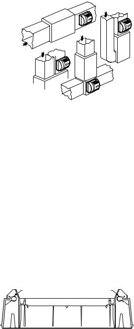
RETURN
HORIZONTAL
RETURN
RETURN
RETURN 
DOWN FLO
BOY
LOW
HIGHBOY
M12808B
Fig. 2. Selecting duct location for humidistat.
Locating Closest 120V Electrical Outlet
•Select location with access to an outlet. If not available, contact an electrician to have one installed.
•Make sure that the humidifier cord is adequate to reach from the humidifier to the outlet.
•Make sure that the 20 ft (6.2m) of thermostat wire is adequate to reach from the humidifier solenoid, to the sail switch, to the humidistat.
Installing the Humidifier
 WARNING
Hazardous Voltage
Can cause personal injury or equipment damage.
Do not cut or drill into any air conditioning or electrical accessory.
 CAUTION
Sharp Edges Installation Hazard.
Can cause personal injury.
Wear gloves and safety glasses.
1.Position the securing clips as shown in Fig. 3.
CLIP |
CLIP |
M12813
Fig. 3. Position securing clips.
Loading...