


Honeywell F50e1281, F50e1166, F50e1073, F50e1158, F50e1141 Product Data
...F50E
Duct Mounted Electronic Air Cleaner
APPLICATION
The F50E high efficiency electronic air cleaner is mounted in the return air duct of a forced air heating, cooling, or ventilating system. It captures a significant amount of the airborne particles 0.5 microns and larger from the air circulated through it.
PRODUCT DATA
FEATURES
•Available in two sizes to fit most ducts; adapts to air flow from either side.
•Has two cells.
•Capacity of 1400 cfm (2380 m3/hr) or 2000 cfm (3400 m3hr), depending on size.
•Solid state power supply is self-regulating and maintains peak efficiency over a wide range of cell dirt loading conditions.
•Pressure drop is approximately equal to that of a regular fiberglass filter.
•Optional W8600E Solid State Performance Indicator monitors air cleaner performance, reminds homeowner when a cell and prefilter wash is past due, and when to check system.
•Electronic cells can be washed in most home dishwashers.
•Remote mount kit is available for mounting power supply and junction box separately when access space is not available.
•Galvanized cabinet protects against rust.
•Automatic interlock switch disconnects power and discharges cell when door is opened.
•Test button checks system operation.
•Troubleshooting guide mounted inside cell access door.
•Permanent wash reminder schedule mounted on top of power supply box.
•Prefilter screens protect cells from large dirt particles.
|
Contents |
Application ........................................................................... |
1 |
Features .............................................................................. |
1 |
Specifications ...................................................................... |
2 |
Ordering Information ........................................................... |
2 |
Planning The Installation ..................................................... |
4 |
Installation ........................................................................... |
8 |
Checkout ............................................................................. |
15 |
Service ................................................................................ |
15 |
Electrical Troubleshooting ................................................... |
18 |
Parts List ............................................................................. |
22 |
Copyright © 1998 Honeywell Inc. • All Rights Reserved |
68-0072-5 |

F50E DUCT MOUNTED ELECTRONIC AIR CLEANER
SPECIFICATIONS
IMPORTANT
The specifications given in this publication do not include normal manufacturing tolerances. Therefore, this unit may not match the listed specifications exactly. Also, this product is tested and calibrated under closely controlled conditions, and some minor differences in performance can be expected if those conditions are changed.
Model:
F50E Electronic Air Cleaner. Includes cabinet, access door, solid state power supply, junction box, 2 electronic cells and 2 prefilters.
Electrical Ratings:
Voltage and frequency: 120V, 60 Hz.
Power consumption: 33W maximum.
Current draw: See Table 1.
Ionizer voltage: 8150 Vdc.
Collector voltage: 4075 Vdc.
Table 1. F50E Current Draw.
|
|
|
|
|
F50E Size |
No. |
Maximum Current (A) |
||
in. |
mm |
Cells |
120V |
240V or 220/240V |
|
|
|
|
|
16 x 25 |
406 x 635 |
2 |
0.3 |
0.2 |
|
|
|
|
|
20 x 25 |
508 x 635 |
2 |
0.3 |
0.2 |
|
|
|
|
|
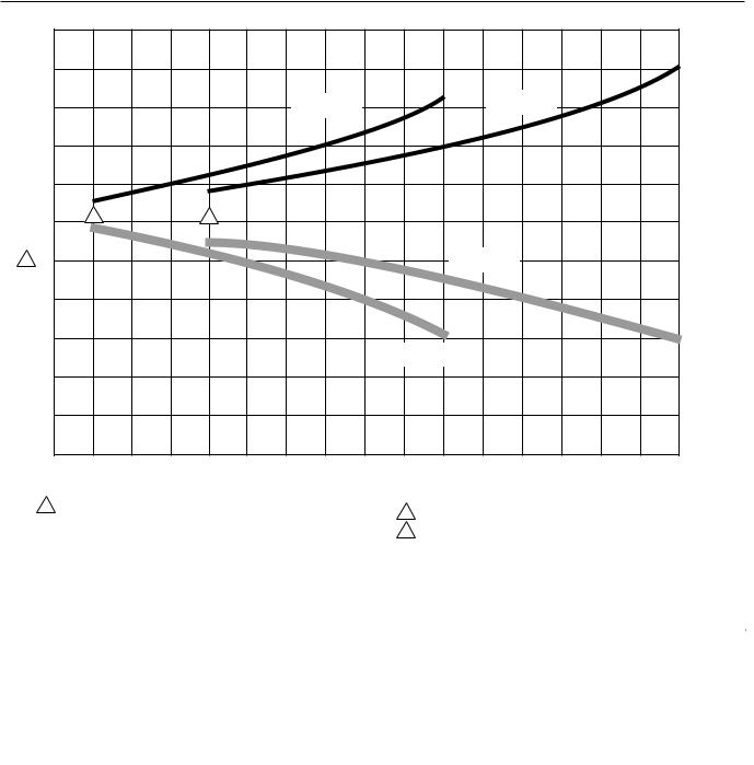
Capacity, Efficiency, Pressure Drop:
See Fig. 1.
Temperature Ratings:
Operating Ambient: 40°F to 125°F (4°C to 52°C). Temperature of Airflow through Cells: 40°F to 125°F
(4°C to 52°C).
Maximum Cell Washing Temperature: 220°F (140°C). Storage and Shipping Ambient: -40°F to +140° F
(-40°C to +60°C).
Mounting:
Mounts in the return air duct of a forced air heating, cooling, or ventilating system. Should be mounted upstream of atomizing humidifier. See Planning the Installation.
Weight:
See Table 2.
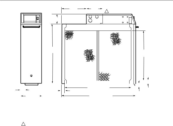
Dimensions:
See Fig. 2.
Approvals:
Underwriters Laboratories Inc. Listed:
File No. E30954, Guide No. AGGZ.
Canadian Standards Association Certified:
File No. LR20633—L, Guide No. 2010.
Option:
W8600E Solid State Performance Indicator (SSPI).
Accessories:
S688A Sail Switch.
136377A Remote Mounting Kit for power supply and junction box. Kit includes galvanized steel base (5 in. [127 mm] wide x 16-1/2 in. [419 mm] long x 13/16 in. [21 mm] deep), prewired flexible conduit with connectors (10 ft. [3m] long), knockout plug, and mounting hardware.
Repair Parts:
See Parts List section.
ORDERING INFORMATION
When purchasing replacement and modernization products from your TRADELINE® wholesaler or distributor, refer to the TRADELINE® Catalog or price sheets for complete ordering number .
1. |
Order number. |
4. |
Accessories, if desired. |
2. |
Voltage and frequency. |
5. |
W8600E Solid State Performance Indicator (SSPI), if desired. |
3. |
Dimensions: 16 x 25 or 20 x 25 in. |
6. |
Model with or without solid state air flow switch. |
|
(406 x 635 or 508 x 635 mm). |
|
|
If you have additional questions, need further information, or would like to comment on our products or services, please write or phone:
1.Your local Home and Building Control Sales Office (check white pages of your phone directory).
2.Home and Building Control Customer Relations Honeywell, 1885 Douglas Drive North Minneapolis, Minnesota 55422-4386
In Canada—Honeywell Limited/Honeywell Limitee, 35 Dynamic Drive, Scarborough, Ontario M1V 4Z9. International Sales and Service Offices in all principal cities of the world. Manufacturing in Australia, Canada, Finland, France, Germany, Japan, Mexico, Netherlands, Spain, Taiwan, United Kingdom, U.S.A.
68-0072—5 |
2 |
F50E DUCT MOUNTED ELECTRONIC AIR CLEANER
|
|
|
|
|
|
|
|
|
|
|
|
|
|
|
|
|
.25 |
|
|
|
|
|
|
|
|
|
|
|
|
|
|
|
|
|
|
(62.2) |
|
|
|
|
|
|
|
|
|
|
|
|
|
|
|
|
|
|
.20 |
(Pa) |
|
|
|
|
|
|
|
|
|
|
|
|
|
|
|
|
|
(49.7) |
in. wc |
|
|
|
|
|
|
|
16 x 25 in. |
|
|
|
20 x 25 in. |
|
|
|
|
|||
|
|
|
|
|
|
|
|
|
|
|
|
|
.15 |
IN |
||||
|
|
|
|
|
|
|
|
|
|
(508 x 635 mm) |
|
|
||||||
|
|
|
|
|
|
|
(406 x 635 mm) |
|
|
|
|
|||||||
|
|
|
|
|
|
|
|
|
|
|
|
|
|
(37.3) |
DROP |
|||
|
|
|
|
|
|
|
|
|
|
|
|
|
|
|
|
|
||
|
|
|
|
|
|
|
|
|
|
|
|
|
|
|
|
|
|
|
|
|
|
|
|
|
|
|
|
|
|
|
|
|
|
|
|
.10 |
PRESSURE |
|
|
|
|
|
|
|
|
|
|
|
|
|
|
|
|
|
(24.9) |
|
|
|
|
|
|
|
|
|
|
|
|
|
|
|
|
|
|
.05 |
|
|
|
|
|
|
|
|
|
|
|
|
|
|
|
|
|
|
(12.4) |
|
|
100 |
2 |
|
|
3 |
|
|
|
|
|
|
|
|
|
|
|
0 |
|
1 |
90 |
|
|
|
|
|
|
|
|
|
20 x 25 in. |
|
|
|
|
|
|
|
|
|
|
|
|
|
|
|
|
(508 x 635 mm) |
|
|
|
|
|
||||
PERCENT |
|
|
|
|
|
|
|
|
|
|
|
|
|
|
|
|||
80 |
|
|
|
|
|
|
|
|
|
|
|
|
|
|
|
|
|
|
|
|
|
|
|
|
|
|
|
|
|
|
|
|
|
|
|
|
|
EFFICIENCY, |
70 |
|
|
|
|
|
|
|
|
|
|
|
|
|
|
|
|
|
|
|
|
|
|
|
|
|
|
16 x 25 in. |
|
|
|
|
|
|
|
||
|
|
|
|
|
|
|
|
|
(406 x 635 mm) |
|
|
|
|
|
|
|
||
|
|
|
|
|
|
|
|
|
|
|
|
|
|
|
|
|
|
|
|
60 |
|
|
|
|
|
|
|
|
|
|
|
|
|
|
|
|
|
|
50 |
|
|
|
|
|
|
|
|
|
|
|
|
|
|
|
|
|
|
400 |
500 |
600 |
700 |
800 |
900 |
1000 |
1100 |
1200 |
1300 |
1400 |
1500 |
1600 |
1700 |
1800 |
1900 |
2000 |
|
|
(680) |
(850) |
(1020) |
(1190) |
(1360) |
(1530) |
(1700) |
(1870) |
(2040) |
(2210) |
(2380) |
(2550) |
(2720) |
(2890) |
(3060) |
(3230) |
(3400) |
|
CAPACITY IN cfm (m3 /hr)
1EFFICIENCY RATINGS BASED ON NATIONAL BUREAU OF
STANDARDS INITIAL DUST SPOT METHOD USING ATMOSPHERIC |
2 MINIMUM RECOMMENDED cfm FOR 16 x 25 in. (406 x 635 mm) MODEL. |
|
|
||
DUST, AND AMERICAN SOCIETY OF HEATING, REFRIGERATING |
3 MINIMUM RECOMMENDED cfm FOR 20 x 25 in. (508 x 635 mm) MODEL. |
|
AND AIR CONDITIONING ENGINEERS STANDARDS 52-76. |
||
|
||
|
M4686 |
Fig. 1. Air cleaner efficiency and pressure drop at various airflow rates.
Table 2. Shipping and Installation Weight.
|
|
|
|
|
|
|
|
|
Weight |
|
|
|
|
|
|
|
|
|
16 x 25 in. (406 x 635 mm) |
|
20 x 25 in. (508 x 635 mm) |
||
|
|
|
|
|
|
|
lb. |
kg |
|
lb. |
kg |
|
|
|
|
|
|
Electronic Cell (each) |
6-1/2 |
3.0 |
|
8-3/16 |
3.7 |
|
|
|
|
|
|
Shipping Weight |
38 |
17.2 |
|
43 |
19.5 |
|
|
|
|
|
|
Installed Weight (cells included) |
33 |
15.0 |
|
38 |
17.2 |
|
|
|
|
|
|
3 |
68-0072—5 |
F50E DUCT MOUNTED ELECTRONIC AIR CLEANER
DIM. C |
5-9/16 |
|
(SEE TABLE) |
(142) |
1 |
|
|
|
3-3/4
(95)
DIM. A |
|
(SEE TABLE) |
DIM. B |
|
|
|
(SEE TABLE) |
|
|
|
|
|
|
|
|
|
|
|
|
|
|
|
|
|
|
|
|
|
|
|
|
|
|
|
|
|
|
|
|
|
|
|
|
|
|
|
|
|
|
|
|
|
|
|
|
|
|
|
|
|
|
|
|
|
|
|
|
|
|
|
|
|
|
|
|
|
|
|
|
|
|
|
|
|
|
|
|
|
|
|
|
|
|
|
|
|
|
|
|
|
|
|
|
|
|
|
|
|
|
|
|
|
|
|
|
|
|
|
|
|
|
|
|
|
|
|
|
|
|
|
|
|
|
|
|
1-1/8 |
|
|
|
|
|
|
|
|
|
|
|
|
DIM. D (SEE TABLE) |
|
|
|
|
|
|
|
|
|
|
|
|
|
|
7/8 |
|
||||||
|
|
|
|
|
|
|
|
15/16 |
|
|
|
|
|
|
|
|
|
|
|
|
|
|
|
|
|
|
|
|
|
|
|
|
|
|
||||||
|
|
|
|
|
|
|
|
|
|
|
|
|
|
|
|
|
|
|
|
|
|
|
|
|
|
|
|
|
5/8 |
(22) |
||||||||||
|
|
|
|
|
(29) |
|
|
|
(24) |
|
|
|
|
|
|
|
|
|
|
|
|
|
|
|
|
|
|
|
|
|
||||||||||
|
|
|
|
|
|
|
|
|
|
|
|
|
|
|
|
|
|
|
|
|
|
|
|
|
|
|
|
|
|
|
|
|
||||||||
|
|
|
6-3/4 (171) |
|
|
|
|
|
|
|
|
|
|
|
|
DIM. E (SEE TABLE) |
|
|
|
|
|
|
|
|
|
(16) |
|
|
|
|
||||||||||
|
|
|
|
|
|
|
|
|
|
|
|
|
|
|
|
|
|
|
|
|
|
|
|
|
|
|
|
|
|
|
|
|
|
|
|
|
|
|
|
|
|
|
|
|
UNIT SIZE |
|
DIM. A |
|
|
|
DIM. B |
|
DIM. C |
|
|
DIM. D |
|
|
|
|
|
|
|
DIM. E |
|
|
|
|
|||||||||||||
|
|
|
|
IN. |
|
|
MM |
|
IN. |
|
MM |
IN. |
|
MM |
IN. |
|
MM |
|
IN. |
|
MM |
|
|
|
IN. |
|
MM |
|
||||||||||||
|
16 |
X 25 |
|
406 X 635 |
17-3/4 |
|
450 |
|
|
14-3/8 |
|
365 |
10-7/16 |
|
265 |
|
23-1/4 |
|
591 |
|
|
25-1/2 |
|
|
|
648 |
|
|
||||||||||||
|
20 |
X 25 |
|
508 X 635 |
21-3/4 |
|
553 |
|
|
18-3/8 |
|
467 |
10-7/16 |
|
265 |
|
23-1/4 |
|
591 |
|
|
25-1/2 |
|
|
|
648 |
|
|
||||||||||||
1 |
|
JUNCTION BOX AND POWER SUPPLY CAN BE REMOTE-MOUNTED USING 136377A REMOTE MOUNT KIT. |
|
|
|
|
|
|
|
|
|
|
M4697 |
|||||||||||||||||||||||||||
Fig. 2. Installation dimensions in in. (mm in brackets) of 2-cell electronic air cleaner.
PLANNING THE INSTALLATION
Application
The F50E is used in a forced air heating, cooling, or ventilating system. It operates when the system blower is on. Models with internal solid state air flow switch require only line voltage connection. Models without the air flow switch can be energized through the fan switch, a dpdt fan relay or an air flow switch such as the S688 Sail Switch. Unless the F50E with solid state air flow switch is used, an isolating fan relay or air flow switch is required if the system has a multispeed or modulating blower motor.
Review Installation Requirements
The air cleaner should be installed where all the air passing through the system circulates through it. The best location is in the return air duct next to the blower compartment so the air cleaner can help keep the blower motor and evaporator coils clean. Do not mount in the discharge air duct.
For most efficient air cleaning, airflow must be spread evenly across the face of the air cleaner. If the duct is a different size than the air cleaner cabinet, gradual transitions are recommended. If the duct turns sharply just before the air cleaner, turning vanes are recommended.
Applications with Air Conditioning
The air cleaner should be installed upstream of the evaporator coil. The air cleaner helps keep the coil clean, reducing maintenance. Also, if the air cleaner is downstream, the high relative humidity of the cooled air leaving the evaporator coil can cause water condensation on the cells, reducing air cleaner efficiency.
Applications with a Humidifier
An evaporative humidifier can be mounted upstream of the air cleaner. An atomizing humidifier should be mounted downstream of the air cleaner, even though hard water salts will be blown into the living space and deposited as dust. If an atomizing humidifier must be mounted upstream of the air cleaner:
1.Mount it as far as possible upstream of the air cleaner.
2.Install a standard disposable furnace filter between the humidifier and the air cleaner to trap water droplets and hard water salts.
3.Clean the air cleaner frequently to prevent a hard water salt buildup.
4.Note that the volume of water that passes through an atomizing humidifier can overload the air cleaner, resulting in hard water salts being deposited as dust in the living space.
68-0072—5 |
4 |
F50E DUCT MOUNTED ELECTRONIC AIR CLEANER
Applications with an Activated Carbon Filter
If desired, an activated carbon (charcoal) filter can be used to remove odors or other gaseous contaminants (not particlebased), which are not removed by the air cleaner. Locate the carbon filter:
•Downstream from the air cleaner. This means, of course, that dust from the carbon filter will not be collected by the air cleaner and will be deposited in the living space.
•Outside the air cleaner cabinet. Some carbon filters are combustible, and contact with high voltage could result in smoke or fire.
•Where carbon granules cannot fall into the electronic cell(s). Use a disposable furnace filter if necessary between the carbon filter and the electronic cell(s).
•With proper transitions, if the activated carbon filter requires a different size duct than the air cleaner. Allow 20 degrees expansion per side, per fitting.
Applications with Outdoor Air Intake
Return air temperature must be at least 40°F (4°C). Lower temperatures can cause ionizer wire failure. If outdoor air is used, warm it ahead of the air cleaner by:
•Making sure the outdoor intake is far enough ahead of the air cleaner so the return and outdoor air is thoroughly mixed. Stratified air can dump a stream of very cold air into one section of the air cleaner.
•Adding baffles ahead of the air cleaner to force thorough air mixing.
•Installing a preheater, if large amounts of outdoor air are used. The preheater, which could be an electric strip heater or hot water coil, should be controlled by a thermostat. Hot water or steam coils should be protected by a freeze-up control.
Choose Location
Choose a location that is readily accessible for regular inspection and cleaning. Allow at least 13 in. (330 mm) in front of the access door for removing the prefilters and electronic cells. Allow enough room above the power supply so the power supply can be serviced without removing pipes, ducts, or other heating system components.
The air cleaner must be installed where the temperature will not exceed the ratings in the SPECIFICATIONS section.
Choose Mounting Position
WARNING
Heavy Equipment.
Can cause injury or equipment damage.
If the access door faces down, the latch may not hold, and the cells and prefilters can fall unexpectedly. Also, nothing holds the cells and prefilters in place once the access door is opened.
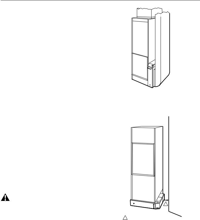
The air cleaner can be mounted in any position except with the access door facing down. Figs. 3-10 show proper air cleaner mounting with a variety of furnace installations.
M6028A
Fig. 3. Highboy furnace, side installation, air cleaner is mounted vertically where return enters side inlet of furnace.
1
1ALLOW AT LEAST 2 IN. (51 MM) BETWEEN TOP OF POWER BOX NAD ADJACENT WALL.
M4691
Fig. 4. Highboy furnace. Installation beneath furnace (air cleaner cabinet can easily support weight of furnace and air conditioner coil). Air cleaner is mounted horizontally where return enters from below.
5 |
68-0072—5 |

F50E DUCT MOUNTED ELECTRONIC AIR CLEANER
1
1
2
1ALLOW AT LEAST 13 IN. (0.3M) CLEARANCE BETWEEN ACCESS DOOR AND WALL FOR CELL AND PREFILTER MAINTENANCE.
2LOCAL CODES MAY PRESCRIBE GRILLE DESIGN AND PROVISION FOR MAKE UP AIR. A SEAL FROM F50 TO GRILLE MAY BE REQUIRED.
M4695
Fig. 5. Highboy furnace. Closet installation. Air cleaner is mounted vertically on furnace between furnace and louvered return air opening in closet door.
1 ACCESS TO AIR CLEANER FROM ATTIC IS REQUIRED FOR CELL AND PREFILTER MAINTENANCE. CONSIDER USING F52E
CEILING MOUNT AIR CLEANER.
M4690
Fig. 7. Horizontal furnace. Air cleaner is mounted horizontally above ceiling. Unless air cleaner is easily accessible from attic, consider using F52 ceiling mount air cleaner instead.
1
M4687
2
1ALLOW AT LEAST 2 IN. (51 MM) CLEARANCE BETWEEN POWER BOX AND FLUE PIPE.
2ALLOW AT LEAST 13 IN. (0.3M) CLEARANCE BETWEEN ACCESS DOOR AND WALL FOR CELL AND PREFILTER MAINTENANCE.
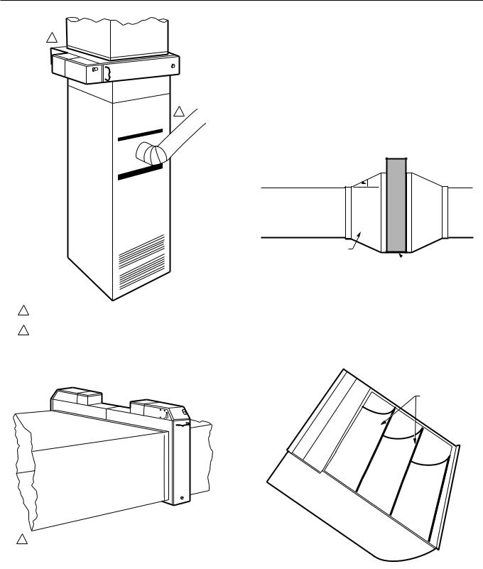
Fig. 8. Horizontal furnace. Air cleaner is mounted vertically in the return duct near the furnace.
Note transition.
M4692
Fig. 6. Lowboy furnace. Air cleaner is mounted horizontally in return plenum just above furnace, opposite supply plenum.
68-0072—5 |
6 |
F50E DUCT MOUNTED ELECTRONIC AIR CLEANER
1
2
1IN CLOSET INSTALLATION, AIR CLEANER MUST BE BELOW TOP OF DOOR FRAME FOR CELL AND PREFILTER MAINTENANCE.
2IF FLUE PIPE IS IN FRONT OF AIR CLEANER, ALLOW AT LEAST
13 IN. (0.3 M) CLEARANCE BETWEEN ACCESS DOOR AND FLUE PIPE.
M4688
Fig. 9. Counterflow furnace. Air cleaner is mounted horizontally in return duct or plenum just above furnace.
1ALLOW AT LEAST 13 in. (0.3 m) CLEARANCE BETWEEN ACCESS DOORS AND ANY OBSTRUCTION FOR CELL AND PREFILTER MAINTENANCE.
M4689
Fig. 10. High capacity system. Two or more air cleaners can be used together. At least 13 in. (0.3m) clearance is required between access doors and walls for cells and prefilter maintenance.
Determine Sheetmetal Requirements
The air cleaner is adaptable to all new or existing residential forced air heating, cooling and ventilating systems. Sheetmetal transitions, turning vanes, or offsets may be needed in some applications.
Transitions
Transitions are needed when the duct is a different size than the air cleaner cabinet. Gradual transitions reduce air turbulence and increase efficiency. Limit expansion to
20 degrees (about 4 in. per running foot [100 mm per 300 linear mm]) on each side of a transition fitting. See Fig. 11.
20 DEGREE EXPANSION PER SIDE. PER FITTING (4 IN. PER RUNNING FOOT [100 MM PER
300 LINEAR MM])
RETURN AIR
DUCT
TRANSITION FITTING
 AIR CLEANER
CABINET M6026
Fig. 11. Change duct size gradually to minimize turbulence.
Turning Vanes
If the air cleaner is installed close to an elbow or angle fitting, install turning vanes inside the angle to distribute airflow more evenly across the face of the cells. See Fig. 12.
TURNING
VANES
M5651
Fig. 12. Turning vanes installed in a bend help distribute airflow evenly over the face of the electronic cells.
7 |
68-0072—5 |

F50E DUCT MOUNTED ELECTRONIC AIR CLEANER
Offsets
If the duct connection to the furnace in a side installation allows less than 7 in. (178 mm) for mounting air cleaner cabinet, shorten the lateral trunk or add an offset to the elbow. See Fig. 13.
OFFSET
LESS
THAN
7 INCHES
(178 MM)
AT LEAST 1 7 INCHES (178 MM)
1 REQUIRED TURNING VANES HELP DISTRIBUTE AIRFLOW EVENLY.
M6027A
Fig. 13. Typical use of duct offset to make room for electronic air cleaner.
INSTALLATION
When Installing this Product…
1.Read these instructions carefully. Failure to follow them could damage the product or cause a hazardous condition.
2.Check the ratings given in the instructions and on the product to make sure the product is suitable for your application.
3.Installer must be a trained, experienced service technician.
4.After installation is complete, check out product operation as provided in these instructions.
 CAUTION
Electric Shock Hazard.
Can cause electrical shock or equipment damage.
Disconnect power supply before installing air cleaner.
Unpack Electronic Air Cleaner
Check that all components are included. The electronic air cleaner is shipped assembled. See Fig. 14. The unit consists of:
•Galvanized steel cabinet.
•Power supply with on-off switch and neon light.
•Junction box.
•Two electronic cells.
•Two prefilters.
•Access door with test button.
•Literature package.
W8600E (optional) and mounting hardware must be ordered separately.
ON-OFF SWITCH WITH NEON LIGHT
WASH REMINDER SCHEDULE
POWER SUPPLY
 JUNCTION BOX
 CABINET
 ELECTRONIC
CELLS
PREFILTERS
TEST BUTTON
 ACCESS DOOR
M7682
OPTIONAL W8600E WALL PANEL
Fig. 14. Components of the F50E Air Cleaner (2-cell model shown).
Clean Blower Compartment
Remove and discard the existing furnace filter.
Thoroughly clean the blower compartment.
If possible, power vacuum ductwork to remove accumulated dust in existing home, or construction dirt in a new home. The electronic air cleaner cannot remove dust that has settled in the blower compartment and distribution ducts.
Check the edges of the furnace fan blades for dirt buildup and clean as necessary. The fan will not deliver the rated cfm if the blades are dirty.
Review the Installation Plan
Temporarily place the cabinet on the floor; position as it will be when installed.
Remove and set aside the access door, electronic cells and prefilters, checking that the selected location provides enough clearance for easy removal and replacement of these components. Unless the power supply will be remotely mounted, make sure there is room above the unit to wire and service the power supply, including the optional W8600E.
Make sure that shop-fabricated sheetmetal components, such as turning vanes, are on hand.
Remote Mount Power Supply, if Desired
If remote mount is not desired, go on to Fasten the Cabinet to the Furnace section.
68-0072—5 |
8 |
 Loading...