


 Loading...
Honeywell DS06-100-SUS-LF, DS06-101-SUS-LF, DS06-102-SUS-LF, DS06-103-SUS-LF, DS06-104-SUS-LF Installation Manual
...DS06 Low Lead Content
Dial Set Pressure Regulating
Valves
|
INSTALLATION INSTRUCTIONS |
APPLICATION |
to 60° C). |
|
Ambient Temperature Range: 33° F to 140° F (1° C |
The Honeywell DS06 Dial Set® Pressure Regulating |
Pipe Sizes Available: 1/2 in., 3/4 in., 1 in., 1-1/4 in., |
Valve is a high quality pressure regulating valve that |
1-1/2 in. and 2 in. available. |
maintains a constant outlet pressure over a wide |
Connections: |
range of inlet supply pressures. It is suitable for |
|
potable water and irrigation applications. The |
Can be configured as female thread-by-thread, |
downstream pressure adjustment dial eliminates the |
singleor double-union, NPT threaded or sweat. |
need for a pressure gauge when adjusting the |
Low Lead Content: < 0.25% Lead. |
pressure setting (static pressure only). |
|
|
Gauge Tap: 1/4" NPT. |
SPECIFICATIONS
Model: DS06 Dial Set Pressure Regulating Valves.
Construction Materials:
Body: Brass.
Internal Parts: Stainless steel and engineered plastics.
Regulator Mechanism: Fabric-reinforced diaphragm.
Seat Design: Balanced single seat construction.
Inlet Pressure (Maximum): 250 psi maximum.
Reduced Pressure Range:
25 to 90 psi (1/2 in. to 2 in.).
Outlet Pressure: Factory set at 60 psi (414 kPa).
Dial Calibration: ± 4 psi.
Differential: 14.5 psi minimum (inlet to outlet).
Fluid Temperature (Maximum):
Water: 140° F (60° C).
Approvals:
ASSE 1003 Listed
CSA Certified
IAPMO/UPC Listed
NSF 61 Compliant
INSTALLATION
When Installing this Product...
1.Read these instructions carefully. Failure to follow them could damage the product or cause a hazardous condition.
2.Check the ratings given in these instructions and on the product to make sure the product is suitable for your application.
3.Installer must be a trained, experienced service technician.
4.After installation is complete, check out the product operation as provided in these instructions.
33-00014EF-07
DS06 LOW LEAD CONTENT DIAL SET PRESSURE REGULATING VALVES
Water Capacities
The suitability of a given regulator size is dependent on the pressure requirements where it will operate. For the pressure regulator valve size required for a specific installation, determine the following:
1.Pressure differential between inlet and outlet pressure in pounds per square inch (psi),
2.Capacity in gallons per minute, and
3.Allowable reduced pressure falloff in psi. Given these variables, use Table 1 to determine the proper size pressure regulator valve for your application.
Example: An installation has 135 psi inlet pressure, 60 psi outlet pressure (75 psi pressure differential). If a 15 gpm capacity is required with only 10 psi falloff allowable, a 3/4 in. DS06 is required.
Table 1. Water Capacities.
|
|
|
|
|
|
|
|
Pressure Differential Between Inlet and Outlet |
|||
|
|
|
|
|
100 psi or |
Pressure |
Reduced |
25 psi |
50 psi |
75 psi |
more |
Regulator |
Pressure |
Flow Capacity |
Flow Capacity |
Flow Capacity |
Flow Capacity |
Valve Size |
Falloff (PSI) |
(US gpm) |
(US gpm) |
(US gpm) |
(US gpm) |
1/2" |
6 |
7.26 |
8.15 |
7.44 |
6.47 |
|
|
|
|
|
|
|
10 |
10.7 |
10.66 |
9.69 |
8.85 |
|
|
|
|
|
|
|
15 |
14.27 |
15.72 |
14.49 |
13.96 |
|
|
|
|
|
|
|
20 |
17.74 |
19.59 |
18.98 |
18.1 |
|
|
|
|
|
|
3/4" |
6 |
11.98 |
14.44 |
14.53 |
14.97 |
|
|
|
|
|
|
|
10 |
17.17 |
21.05 |
25.23 |
26.33 |
|
|
|
|
|
|
|
15 |
19.86 |
25.14 |
29.32 |
32.85 |
|
|
|
|
|
|
|
20 |
21.27 |
26.42 |
30.42 |
33.82 |
|
|
|
|
|
|
1" |
6 |
11.18 |
11.23 |
9.51 |
9.11 |
|
|
|
|
|
|
|
10 |
18.01 |
18.98 |
17.39 |
16.78 |
|
|
|
|
|
|
|
15 |
25.67 |
28.14 |
28.71 |
26.9 |
|
|
|
|
|
|
|
20 |
30.69 |
34.7 |
36.19 |
35.05 |
|
|
|
|
|
|
1-1/4" |
6 |
7.53 |
6.34 |
7.26 |
7.13 |
|
|
|
|
|
|
|
10 |
20.25 |
17.88 |
15.15 |
14 |
|
|
|
|
|
|
|
15 |
33.02 |
34.87 |
32.63 |
29.68 |
|
|
|
|
|
|
|
20 |
40.07 |
44.29 |
46.01 |
34.61 |
|
|
|
|
|
|
1-1/2" |
6 |
29.81 |
32.27 |
30.87 |
26.81 |
|
|
|
|
|
|
|
10 |
46.14 |
50.02 |
49.89 |
47.82 |
|
|
|
|
|
|
|
15 |
66.22 |
78.42 |
86.74 |
84.14 |
|
|
|
|
|
|
|
20 |
77.14 |
92.29 |
103.82 |
109.68 |
|
|
|
|
|
|
2" |
6 |
27.34 |
25.8 |
24.48 |
18.01 |
|
|
|
|
|
|
|
10 |
64.81 |
97.61 |
78.15 |
90.09 |
|
|
|
|
|
|
|
15 |
82.82 |
105.14 |
119.94 |
129.62 |
|
|
|
|
|
|
|
20 |
87.66 |
107.83 |
120.95 |
132.09 |
|
|
|
|
|
|
DSO6 Fixture Unit
Flow rates based on submittal sheet DS06, based on flush tank systems with a 15 psi fall-off defined by IAPMO/ANSI UPC 1-2009.
Table 2.
|
|
|
|
|
|
|
Fixture |
Size |
I/s |
GPM |
Units |
1/2” |
0.99 |
15.72 |
21 |
|
|
|
|
3/4” |
1.58 |
25.14 |
40 |
|
|
|
|
1” |
1.77 |
28.14 |
48 |
|
|
|
|
1-1/4” |
2.19 |
34.87 |
70 |
|
|
|
|
1-1/2” |
4.93 |
78.42 |
270 |
|
|
|
|
2” |
6.61 |
105.14 |
400 |
|
|
|
|
Capacities are based on a 100 psi supply pressure and a difference of 50 psi or more between the initial supply pressure and the reduced no-flow pressure.
Check local water pressures before selection.
Procedure
1.Flush the system clear of sediment or debris.
2.Close the supply valve and downstream isolating valve (if one is installed).
3.Install the DS06 with the arrow on the body pointing in the direction of water flow. Install, preferably, in horizontal pipework with filter bowl downwards - vertical installation also possible.
The DS06 can be installed directly onto the pipe by using the female NPT threads on each end. If space limitations restrict turning the DS06, install singleor double-unions.
33-00014EF—07 |
2 |

DS06 LOW LEAD CONTENT DIAL SET PRESSURE REGULATING VALVES
NOTE: Heat from soldering can damage internal parts of the DS06. Always solder the tailpieces separately from the DS06.
8.Remove cartridge using a pliers as a lever.
9.Reassemble bonnet in reverse order.
4.Open the supply valve slowly and check for leakage and proper operation of the DS06.
Changing the Downstream
Pressure (See Fig. 1)
Remove the dust cap from the DS06. The DS06 is factory set to 60 psi.
To adjust the outlet pressure to a desired setting:
1.Loosen the locking screw by turning counter-
clockwise |
! (Do not remove this screw.) |
2.Turn the adjusting knob counter-clockwise  to reduce pressure or clockwise
  to increase pressure.
3.Lock the setting by turning the locking screw clockwise  .
.
4.Replace the dust cap over the dial.
LOOSEN LOCKING
SCREW ONE TURN
ADJUST SETPOINT AT THE DESIRED VALUE BY ACTUATING SELECTOR.
INLET PRESSURE (MAXIMUM): 250 PSI REDUCED PRESSURE RANGE:
25 TO 90PSI 1/2 IN. TO 2 IN. SIZE
NOTE: DO NOT DISMANTLE KNOB
SET-POINT READOUT HAS BEEN CALIBRATED |
|
IN THE FACTORY AND SET AT 60 PSI. |
|
DISMANTLING THE SELECTOR KNOB WILL |
|
CANCEL THIS CALIBRATION. RECALIBRATE |
|
USING A PRESSURE GAUGE. SEE RECALIBRATION. |
M35046A |
Fig. 1. Changing outlet pressure.
Replacing the Cartridge (Fig. 2)
The working parts of the DS06, including diaphragm, valve seat, strainer, and disk are all contained in a replaceable cartridge. To replace the cartridge:
1.Close shutoff valve on inlet.
2.Release pressure on outlet side (e.g. through water tap).
3.Close shutoff valve on outlet.
4.Loosen slotted screw (do not remove the screw).
 CAUTION
To prevent injury and/or equipment damage, loosen locknut and turn adjusting screw counter-clockwise  to remove spring tension.
5.Slacken tension in compression spring by turning counter clockwise until it does not move anymore.
6.Unscrew Bonnet.
7.Remove slip ring.
Recalibrate
If the dial knob assembly has been disassembled recalibration is necessary.
1. Close shutoff valve on inlet.
2. Release pressure on outlet side (e.g. through water tap).
3. Close shutoff valve on outlet.
4. Remove dust cap.
5. Loosen slotted screw (do not remove screw).
6. Fit pressure gauge.
7. Slowly open shutoff valve on inlet.
8. Set desired outlet pressure (e.g. 60 psi).
9. Align scale (e.g. 60 psi) in middle of viewing window.
10. Retighten slotted screw.
11. Slowly open shutoff valve on outlet.
1 LOOSEN THE SETPOINT DIAL LOCKING SCREW.
2 UNSTRESS THE PRESSURE SPRING
BY TURNING COUNTERCLOCKWISE  .
.
3 UNSCREW THE BONNET WITH A 1-5/8" WRENCH.
1-5/8" WRENCH
4 REMOVE CARTRIDGE USING A PLIERS AS A LEVER.
5 WHEN REASSEMBLING, ENSURE O-RINGS AND WASHER ARE PROPERLY INSTALLED
WASHER  (LIP UP)

O-RINGS 


6 REASSEMBLE BONNET IN REVERSE ORDER.
M35634A
Fig. 2. Replacing the DS06 cartridge.
3 |
33-00014EF—07 |
DS06 LOW LEAD CONTENT DIAL SET PRESSURE REGULATING VALVES
Cleaning
1.Close shutoff valve on inlet.
2.Release pressure on outlet (e.g. through water tap).
3.Close shutoff valve on outlet.
4.Unscrew filter bowl using a 1-5/8" wrench.
5.Remove filter, clean and reinsert.
6.Place O-ring onto filter bowl.
7.Screw in filter cup hand-tight.
8.Slowly open shutoff valve on inlet.
9.Slowly open shutoff valve on outlets.
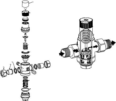
DUST CAP (BLACK)
 LOCKING SCREW


 ADJUSTING
KNOB

 DIAL RING

 BONNET


 SPINDLE
 SPRING

 WASHER


 CARTRIDGE
GASKETS (2)
TAILPIECES (2)
NUTS
(2)


 PLUGS (2)
 REPLACEMENT
FILTER
 O-RING SET
FOR DO6F
OPERATION
DS06 is a spring loaded pressure reducing valve that operates by means of force equalizing system. The force of a diaphragm operates against the force of an adjustment spring. If the outlet pressure and therefore diaphragm force fall because water is dawn, the then greater force of the spring causes the valve to open. The outlet pressure then increases until the forces between the diaphragm and the spring are equal again. The inlet pressure has no influence in either opening or closing the valve. Because of this, inlet pressure fluctuation does not influence the outlet pressure, thus providing inlet pressure balancing. See Fig. 4 for the internal construction of the DS06.
NOTE: Minimum ambient rating is 33° F (1° C).
4
M35052
Fig. 4. Internal construction of DS06.
M35053A
Fig. 3. DS06 exploded view.
33-00014EF—07 |
4 |
Loading...