


Solid Core and Split Core 4-20 mA
Output Current Sensors
CTS-20; CTP-20
INSTALLATION INSTRUCTIONS
SAFETY
3X
 WARNING
For CTS-20 Series current sensors, ensure that all power sources are disconnected and locked out before installation as severe injury or death may result from electrical shock due to contact with high voltage wires.
 CAUTION
This product is not intended to be used for life or safety applications.
 CAUTION
This product is not intended for use in any hazardous or classified locations.
|
S |
|
U |
U |
L |
C |
|
INSTALLATION
Make sure that all installations are in compliance with all national and local electrical codes. Only qualified individuals that are familiar with codes, standards, and proper safety procedures for high-voltage installations should attempt installation. The current sensor is a 2- wire, 4 to 20 mA Loop Powered device that requires a regulated +12 to 30 Vdc external power source.
IMPORTANT
The current switch should be used on insulated conductors only!
The current sensors may be mounted in any position using the two (2) #8 x 3/4 in (19 mm) Tek screws and the mounting holes in the base or snapped directly on to the 1-3/8 in. (35 mm) DIN rail (See Figures 3 and 4). Leave a minimum distance of 1 in. (25 mm) between the current sensor and any other magnetic devices such as contactors and transformers.
M25289
Fig. 1. Sensor placed on DIN rail
3X |
S
U
L
U
C
M25290
Fig. 2. Sensor removed from DIN rail
|
|
|
|
|
|
|
|
|
|
|
|
|
|
|
|
|
|
|
|
|
|
|
|
|
|
|
|
|
|
|
|
|
|
|
|
|
|
|
|
|
|
|
|
|
|
|
|
|
|
|
|
|
|
|
|
|
|
|
|
|
|
|
|
|
|
|
|
|
|
|
|
|
|
|
|
|
|
|
|
|
|
|
|
|
IND.CONT.EQ. |
|
|
|
|
|
|
|
|
|
|
|
|
|
|
|
62-0245—01 |
||||||||||
|
|
3JHX |
|
|
|
|
|
|
|
|
|
|
|
|
|
|
|
|
|
|
|
|
|
|
|
|
|
SOLID CORE AND SPLIT CORE 4-20 MA OUTPUT CURRENT SENSORS
 WARNING
The secondary of the 5A Current Transformer (C.T.) must be shorted together before the power may be turned on from the device.
For applications in which the normal operating current is greater than 200 or 250 Amps, depending on the model, or for conductor diameters larger than 0.75 in. (19 mm) in diameter, an external 5 Amp Current Transformer (C.T.) must be used in conjunction with a CTS20-005 or CTS20005VFD as shown in Fig. 5.
WIRE NUT
INSULATED600:5 RATIO 5A C.T.
CONDUCTOR
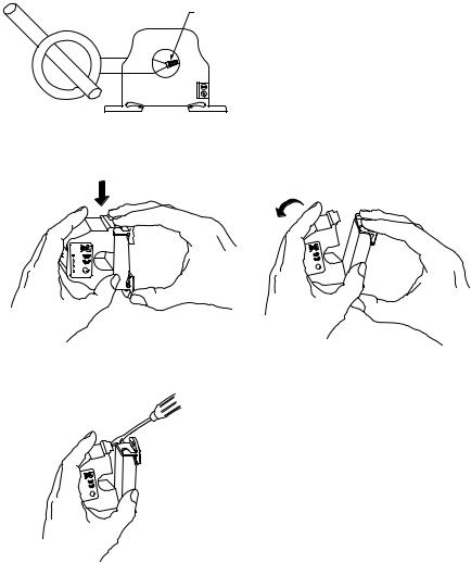
Latch Operation (Split Core Models)
Pressing down on the two (2) side tabs and swinging the cover open, opens the split core current switch as shown in Fig. 6. Lifting up the latch with a flat-tip screwdriver as shown in Fig. 7 can also open the unit. Press down firmly on the cover to close the current switch. An audible “click” will be heard as the tab slides over the tongue on the base.
 CAUTION
Mating surfaces of the magnetic core are exposed when the sensor is open. Silicone grease, present on the cores to prevent rust, can capture grit and dirt if care is not exercised. Operation can be impaired if anything prevents good contact between pole pieces. Visually check the mating parts of the core before closing the current sensor.
EXAMPLE: FOR CURRENTS UP TO 600 AMPS, USE A 600:5 RATIO C.T.
AS SHOWN. |
M25295A |
Fig. 3. Current transformer
LUS
U
C
S
U
L U
C
M25298
Fig. 4. Opening sensor by hand
Wiring
US
L
U
C
M25299
Fig. 5. Opening with a screwdriver
Honeywell recommends the use of 16 to 22 AWG (1.3 to 0.3 mm2) shielded cable, copper wire only for all current sensor applications. A maximum wire length of less than 98.4 feet (30 meters) should be used between the current sensors and the Building Management System or controller.
NOTE: When using a shielded cable, be sure to connect only (1) end of the shield to ground at the controller. Connecting both ends of the shield to ground may cause a ground loop.
When removing the shield from the sensor end, make sure to properly trim the shield so as to prevent any chance of shorting. The current sensor terminals are polarity sensitive and represent a linear and proportional 4 to 20 mA output signal. The current sensors are available in either an Average or True RMS output version. The recommended torque to be used on the terminal block connections is 5.93 in-lbs (0.67 Nm). The
62-0245—01 |
2 |
 Loading...