


CT2700
An Electronic Round™
Programmable Thermostat
Programmable Heat and/or Cool
Low Voltage (20 to 30 Vac) Thermostat and Wallplate Model CT2700
Congratulations on the purchase of your new thermostat! Over 100 years of Honeywell engineering expertise went into the making of this thermostat in an effort to provide you with a more comfortable and convenient living environment.
Your new thermostat will automatically control the temperature in your home, keeping you comfortable while saving energy when programmed according to the instructions in this manual.
Direct any questions concerning the application of this thermostat to Honeywell Customer Assistance at 1-800-468-1502, Monday - Friday 7:00 a.m. - 5:30 p.m., Central time.
USER’S GUIDE
 MERCURY
SWITCH
TYPICAL LOCATION OF A MERCURY
SWITCH IN A THERMOSTAT
M10614
 RECYCLING
THERMOSTAT
If this thermostat is replacing a control that contains mercury in a sealed tube, do not place your old control in the trash. Contact your local waste management authority for instructions regarding recycling and the proper disposal of this control, or of an old control containing mercury in a sealed tube.
If you have questions, call Honeywell, Inc. at 1-800-468-1502.
1 PREPARE FOR INSTALLATION
Check Table 1 to make sure this thermostat is compatible with your system. If not, return to the
retailer. For more information, call Honeywell, Inc. at 1-800-468-1502.
®U.S. Registered |
Trademark |
|
|
|
|
|
|
|
|
|
|
|
|
|
|
|
|
|
|
|
|
|
|
|
|
|
|
|
|
|
|
|
|
|
|
|
|
|
|
|
|
69-1085 |
|||||||||||||||||||||||||||||||||||||
Copyright © 1997 |
Honeywell Inc. • |
• All Rights Reserved |
X-XX UL |
||||||||||||||||||||||||||||||||||||
CT2700 AN ELECTRONIC ROUND ™ PROGRAMMABLE THERMOSTAT
|
Table 1. Compatibility Chart |
|
|
|
|
System Type |
|
Compatible With CT2700 |
|
|
|
Gas—Standing Pilot |
|
Yesa |
Gas—Electronic Ignition |
|
Yes |
Gas-Fired Boilers |
|
Yesa,b |
Gas—Millivolt |
|
No |
Oil-Fired Boilers |
|
Yesb |
Oil-Fired Furnace |
|
Yes |
Electric Furnace |
|
Yes |
Electric Air Conditioning |
|
Yes |
Baseboard Electric (120/240 Line Volt) |
|
No |
Heat Pumps/Multistage Equipment |
|
No |
|
|
|
Not compatible with any 120/240 volt circuit.
Not compatible with 2-wire White-Rodgers no. 1361 zone valves. aNot compatible with millivolt systems.
bCompatible with 2-wire Honeywell zone valves. Isolating relay required for 3-wire thermostats zone valves
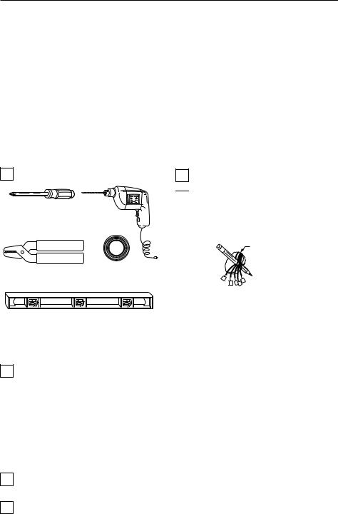
Acquire tools and items as needed. See Fig. 1.
CROSS-RECESSED
SCREWDRIVER HAND OR POWER DRILL WITH 3/16 INCH
DRILL BIT, IF NEEDED TO DRILL HOLES IN WALL
WIRE CUTTER/STRIPPER OR SHARP |
MASKING TAPE, IF |
|
NEEDED TO LABEL WIRES |
||
KNIFE, IF NEEDED TO STRIP WIRES |
||
AS DISCONNECTED FROM |
||
|
||
|
OLD THERMOSTAT |
Loosen screws holding thermostat to subbase, wallplate, to wall and lift away.
 Disconnect wires from old thermostat or subbase. As you disconnect each wire, use masking tape to label it with the old terminal designation. If there are only
two wires, they do not need labeling. Wrap wires around a pencil to keep them from falling back into the wall as shown in Fig. 2.
WIRES THROUGH
WALL OPENING
M5136
LEVEL, IF NEEDED TO LEVEL |
M878B |
|
THERMOSTAT FOR APPEARANCE |
||
|
Fig. 1. Required installation tools/supplies.
2 REMOVE OLD THERMOSTAT
Test to make certain that your heating and air conditioning systems (where applicable) are working
properly. If either does not work, contact your local heating/air conditioning dealer. To avoid compressor damage, do not operate the cooling system when outdoor temperature is below 50°F (10°C).
Fig. 2. Wrapping wires around pencil.
Replacing Clock With C or C1 Clock Terminals
If you are replacing a Honeywell Chronotherm® Thermostat, you may find one or two wires that go to the C or C1 clock terminals on the Chronotherm® Thermostat wiring wallplate. Do not allow them to touch, or you can damage your transformer. Disconnect the wires and wrap them separately using electrical tape; do not wrap them together. Place the wires to avoid interfering with the new thermostat operation. Record the colors and terminal designation labels of the remaining wires.
 CAUTION
Be careful when handling wires during installation.
Damage to heating/cooling system possible.
Disconnect power at furnace or at main breaker/ fuse box before starting operation.
Carefully unpack your new thermostat, wallplate, and decorator cover plate; save package of screws,
instructions and receipt.
Remove the cover from the old thermostat. If it does not snap off when pulled firmly from the bottom,
check for a screw used to lock on the cover.
Six or More Wires
If there are six or more wires connected to the thermostat (excluding clock wires attached to terminals), you probably have a variation of a multistage heat pump or other multistage system. The thermostat is not compatible with such systems so return the product to your retailer. If you would like information about which programmable thermostats work with your system, call Honeywell Customer Assistance Center at 1-800-468-1502.
69-1085 |
2 |

CT2700 AN ELECTRONIC ROUND ™ PROGRAMMABLE THERMOSTAT
Three Thermostat Wires
If you have three wires for heating only and can operate the fan using the FAN ON switch, this thermostat works with your system. However, some hot water (zoned) heating systems have three thermostat wires. The thermostat will work only if you install an isolating relay on these systems. For details, call Honeywell Customer Assistance Center at 1-800-468-1502.
3 MOUNT WALLPLATE
IMPORTANT
Level for appearance only. The thermostat functions normally even when not mounted level.
Position the decorator cover plate and wallplate on the wall. Level the wallplate for appearance if
desired. Use a pencil to mark the two mounting holes that best fit the application. See Fig. 3.
WALL
DECORATOR
COVER PLATE
PLASTIC SCREW
ANCHOR (2)
WALLPLATE 
|
OFF |
HEAT |
|
L |
|
|
O |
|
C |
O |
|
F
A
N
O
N
A
U
T
O
M12532
Fig. 3. Mounting decorator cover plate and wallplate to wall.
Remove the decorator cover plate and wallplate from the wall, and drill two 3/16-inch holes in the wall
(if drywall). For firmer wall material such as plaster or wood, drill 7/32-inch holes. Gently tap provided anchors into the drilled holes until flush with the wall.
Reposition the decorator cover plate and wallplate, pulling wires through the wiring opening. Loosely
insert the mounting screws into the holes.
Level for appearance only; the thermostat functions properly even when not level. Tighten the mounting
screws.
4 WIRE WALLPLATE TERMINALS
The CT2700 Thermostat is powered through the heating/ cooling system and is adaptable to most 4-wire, 18 to 30 Vac heating-cooling systems. Refer to Figs. 4 through 6 for some typical system wiring diagrams.
|
T8700 |
|
R |
|
|
G |
|
|
Y |
COOLING |
|
CONTACTOR |
||
|
||
W |
|
|
HEATING |
FAN |
|
RELAY |
|
|
PRIMARY |
|
1 |
|
|
CONTROL |
|
|
L1 |
|
|
|
|
|
(HOT) |
24V |
|
L2 |
|
|
1 POWER SUPPLY. PROVIDE DISCONNECT MEANS AND
OVERLOAD PROTECTION AS REQUIRED. |
M12525 |
Fig. 4. CT2700 wiring diagram, 4-wire heat/cool system.
T8700
R
G
Y
W
HEATING
1
RELAY AND
FAN COIL
24V
1POWER SUPPLY. PROVIDE DISCONNECT MEANS AND OVERLOAD PROTECTION AS REQUIRED.
M12543
Fig. 5. CT2700 wiring diagram, 2-wire, heat-only system.
|
T8700 |
R |
|
G |
|
Y |
FAN |
|
|
W |
COIL |
|
|
COOLING |
|
1 |
CONTACTOR |
|
COIL |
||
L1 |
||
|
||
(HOT) |
24V |
|
L2 |
|
1POWER SUPPLY. PROVIDE DISCONNECT MEANS AND OVERLOAD PROTECTION AS REQUIRED.
M12544
Fig. 6. CT2700 wiring diagram, 3-wire, cool-only system.
IMPORTANT
Use 18-gauge maximum wire to wire the thermostat.
3 |
69-1085 |
 Loading...