


User Manual

Congratulations on the purchase of your DOMONIAL security system.
This system is designed to operate on an authorised radio frequency and will in no way endanger the user.
To make the best out of your system we advise you to read this manual carefully. This manual has been written for your special attention and integrates remarks and suggestions of existing users.
Full set
Part set
Annex
Zone 1 |
: |
Zone 11 : |
Zone 2 |
: |
Zone 12 : |
Zone 3 |
: |
Zone 13 : |
Zone 4 |
: |
Zone 14 : |
Zone 5 |
: |
Zone 15 : |
Zone 6 |
: |
Zone 16 : |
Zone 7 |
: |
Zone 17 : |
Zone 8 |
: |
Zone 18 : |
Zone 9 |
: |
Zone 19 : |
Zone 10 : |
Zone 20 : |
|
|
|
|
2
INDEX
1
4
7
2 |
|
3 |
5 |
|
6 |
|
8 |
9 |
|
|
|
|
0 |
|
|
|
SOS |
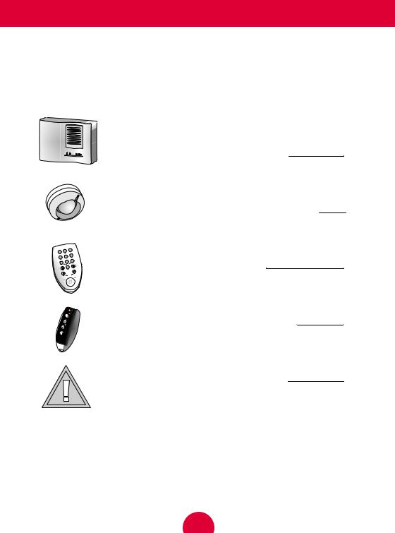
Introduction to your security system
Understanding the audible acknowledgements
How to use your wireless keypad
How to use your keyfob (if purchased)
Maintenance and recommendations
4
6
8
12
15
3
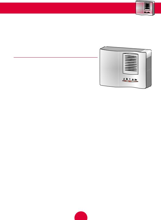
Introduction to your security system
The Domonial control panel/communicator unit is the brain of your security system. It exchanges information with the associated wireless peripherals. The control panel centralises the data sent by the detectors, records the arming and disarming operations and communicates with the Alarm Receiving Centre.
CHARACTERISTICS
Radio
●Narrow band frequency modulation
●Identification code specific to each
component (no possible interference between neighbouring systems)
●Protection against attempted jamming
●Radio monitoring of the system detectors and sounders
Electrical
●240V mains with battery backup
●Built-in voltage surge protection
●System supply monitoring
Transmission
●Built-in telephone transmission
●Telephone line loss detection
●Transmission monitoring by periodical tests (as programmed)
Operational
●3 protected area groups - 20 detection points
●Alert functions, with sounder or silent
●All door and window contacts, closed position checked upon arming
●Control panel tamper protection against opening
4
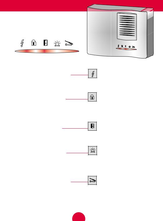
Indicator lights
The front cover of the control panel features LED indicators which show the status of your security system.
1- LED INDICATOR “AC MAINS POWER”
ON : The Control Panel is supplied by the Mains power
OFF : There is a Mains Power Failure – The Control Panel is supplied by its built – in battery
2- LED INDICATOR “SYSTEM ARMED”
ON : The system is totally armed
OFF : The system is disarmed
BLINKING : The system is Part Armed
3- LED INDICATOR “OPEN ZONE”
BLINKING : It means that one of the windows or doors protected by a magnetic contact is opened. It blinks until the window or door has been closed
4- LED INDICATOR “ALARM MEMORY”
ON : It means that an alarm occurred during the ARMING mode
BLINKING : It means that an alarm occurred during the Part arm mode
The indicator remains ON until the next arming
5- LED INDICATOR “SERVICE REQUIRED” |
PLEASE CALL SERVICE DEPT. |
ON : It indicates a fault on a technical channel or a remote reset is required
BLINKING : It indicates a fault on the system ( Battery fault, Supervision, Tamper, Phone line failure or Radio Jamming )
The indicator will remain ON or BLINKING until the condition has been cleared.
5
 Loading...