


CT3600
69-1642
OWNER’S GUIDE
® U.S. Registered Trademark
Copyright © 2002 Honeywell • •All Rights Reserved
Honeywell CT3600/CT3697
PROGRAMMABLE THERMOSTAT
Seven Day Programmable Heat and/or Cool
Low Voltage (20 to 30 Vac) Thermostat and Wallplate
Model CT3600/CT3697
Para obtener un documento con las instrucciones en español, por favor visite
nuestro sitio de web a: www.honeywell.com/yourhome.
Pour obtenir des notices techniques en français, veuillez consulter notre site web
www.honeywell.com/yourhome.
Contents
Step 1. Prepare for Installation ................................................................................................................................... 5
Step 2. Remove Old Thermostat ................................................................................................................................ 6
Step 3. Mount Thermostat Wallplate .......................................................................................................................... 7
Step 4. Wire Wallplate Terminals ................................................................................................................................ 8
Step 5. Install the Batteries ......................................................................................................................................... 9
Step 6. Set Fan Operation Switch .............................................................................................................................. 10
Step 7. Mount the Thermostat .................................................................................................................................... 11
Step 8. Customize Your Thermostat ........................................................................................................................... 11
Step 9. Set the Clock .................................................................................................................................................. 13
Step 10. Programming ................................................................................................................................................ 14
Step 11. Operating Your Thermostat .......................................................................................................................... 17
Step 12. Set the Fan and System Switches ............................................................................................................... 19
If You Have a Problem ................................................................................................................................................ 20
Smart Response™ Technology .................................................................................................................................. 21
Wiring Diagrams ......................................................................................................................................................... 22
69-1642 2
Total comfort temperature management with Smart Response™
Technology.
Congratulations! You made a smart choice by purchasing your new Honeywell thermostat; the smart thermostat that;
• Keeps you comfortable by automatically calculating exactly when the furnace or air conditioning should go on to
have the house at the desired comfort temperature by the time you wake up or return home.
• Saves the maximum amount of energy and money by automatically remembering to adjust the temperature when
you leave home or go to sleep.
• Provides the ultimate in comfort and convenience. It comes preprogrammed. You can use the preprogrammed
schedule, or set your own.
This manual answers many of the questions that can arise as you become familiar and comfortable with your
Honeywell thermostat — the state of the art in home comfort controls.
Read these instructions carefully. Failure to follow these instructions can damage the product or cause a hazardous
condition.
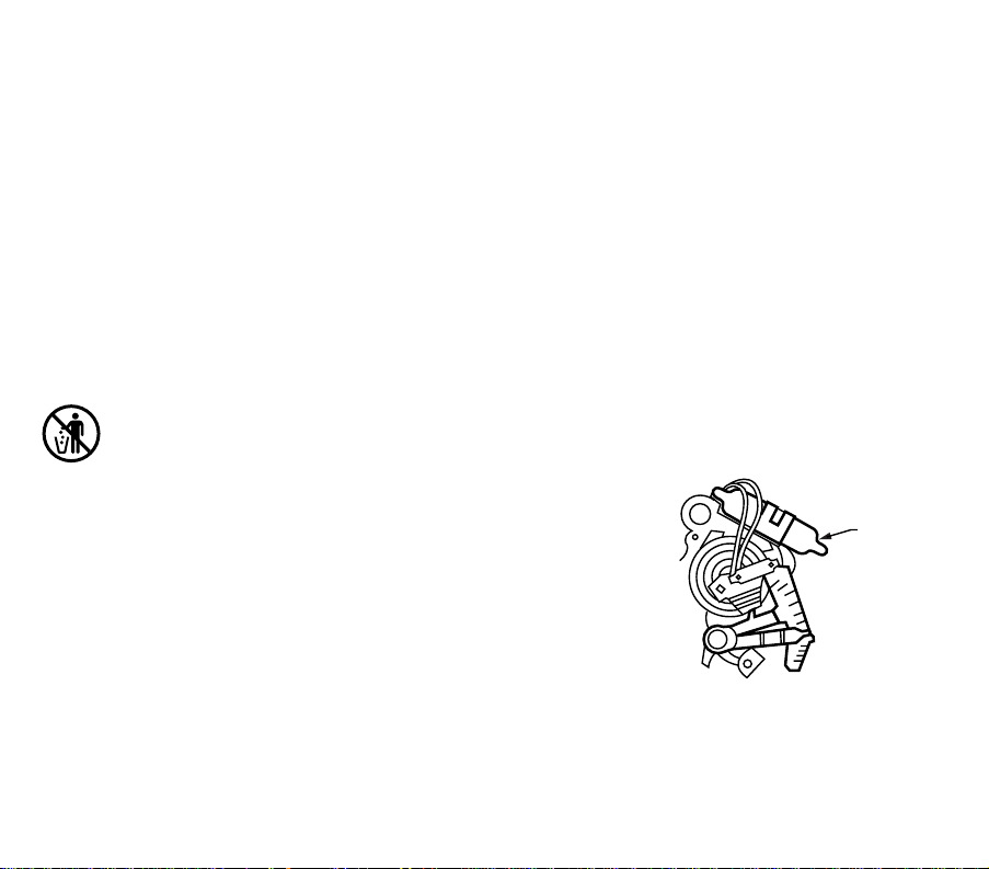
MERCURY NOTICE
If this thermostat is replacing a control that contains mercury
in a sealed tube, do not place your old control in the trash.
Contact your local waste management authority for
instructions regarding recycling and the proper disposal of this
control, or of an old control containing mercury in a sealed
tube.
M10614
MERCUR
Y
SWITCH
T
YPICAL LOCATION OF A MERCURY
S
WITCH IN A THERMOSTAT
3 69-1642
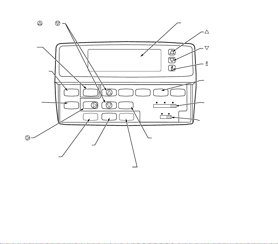
Time Set Program
Run
Program
Hold Temp
Set Current
Day/Time
Day
Heat/Cool
Settings
Daylight
Time
Copy
Usage
System
Fan
Wake
Leave
Return Sleep
Heat Off Cool
On Auto
M18635C
RAISES
TEMPERATURE SETTING
LOWERS
TEMPERATURE SETTING
DISPLAYS
CURRENT HEAT/COOL
TEMPERATURE SETTING
PROGRAM PERIODS
WAKE/LEAVE/RETURN/SLEEP:
ENTERS PROGRAMMING MOD
E
FAN SWITCH
SELECTS AUTO/ON
SYSTEM SWITCH
SELECTS HEAT/OFF/COOL
DIGITAL DISPLAY
S
ET CURRENT
D
AY/TIME
S
ETS CURRENT
T
IME AND DAY
R
UN PROGRAM
R
ETURNS
T
HERMOSTAT
T
O NORMAL
O
PERATING MODE
HEAT/COOL SETTING
SWITCHES BETWEEN
HEAT SETPOINTS AND
COOL SETPOINTS
WHILE PROGRAMMING
TIME /TIME
SETS TIME
FORWARD OR BACK
D
AY
S
ETS DAY OF
T
HE WEEK
H
OLD TEMP
S
ETS A HOLD
T
EMPERATURE
S
ETTING AND
A
CTIVATES
V
ACATION HOLD
F
EATURE
DAYLIGHT TIME
SELECTS STANDARD
TIME OR DAYLIGHT
SAVINGS TIME
COPY
COPY SETTINGS FROM
ONE DAY TO ANOTHER DAY
FOR QUICK PROGRAMMING
USAGE
TRACKS EQUIPMENT RUNTIME
69-1642 4
M16421C
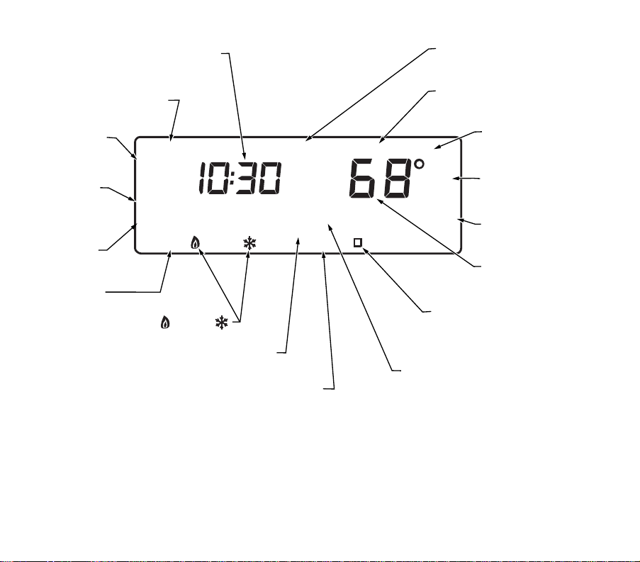
Aux Ht
System
Off Auto
WakeLeaveReturnSleep
Mon
Wait
In
Room
Humid
Outdoor
Filter
AM
Hold for
Repl Batt
Recovery
Cool
TueWedThuFriSatSun Days
Set Program
Set Day/Time
Temporary Setting
Em
Heat
Em Ht
DISPLAYS EITHER CURRENT
TIME OF DAY OR PROGRAM TIMES
SHOWS THERMOSTAT IS IN
THE SET DAY/TIME MODE
SHOWS TEMPERATURE SETTING
CHANGED FOR THIS PROGRAM PERIO
D
SHOWS THE TEMPERATURE
DISPLAYED IS THE CURREN
T
SET TEMPERATURE
SHOWS THE TEMPERATURE
DISPLAYED IS THE CURREN
T
ROOM TEMPERATURE
SHOWS THE BATTERIES ARE
LOW AND MUST BE
REPLACED
DISPLAYS EITHER ROOM
OR SET TEMPERATURES
SHOWS SMART RESPONSE IS OFF.
CONVENTIONAL RECOVERY IS ON
SHOWS THERMOSTAT IS PROCESSING
INFORMATION AND WAITING TO CALL FOR HEAT OR COOL
SHOWS SMART RESPONSE IS CHANGING
THE TEMPERATURE TO MEET THE
CURRENT PROGRAMS
SHOWS THAT THERMOSTAT IS
"CALLING" FOR HEAT OR COOL
SHOWS CURRENT
SYSTEM KEY POSITION
HEAT/OFF/COOL
S
HOWS CURRENT
P
ROGRAM PERIOD
O
R PERIOD BEING
P
ROGRAMMED
S
HOWS CURRENT
D
AY OR DAYS BEING
P
ROGRAMMED
S
HOWS VACATION
H
OLD DURATION
SHOWS WHEN
THERMOSTAT IS IN THE
PROGRAMMING MODE
DST
SHOWS SYSTEM ON DAYLIGHT SAVINGS TIME
5 69-1642
STEP 1. PREPARE FOR INSTALLATION
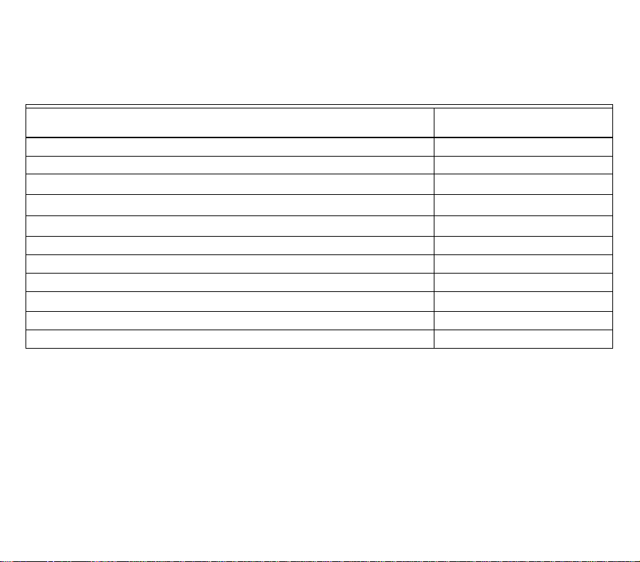
❑ Check Table 1, the compatibility chart, to make sure the thermostat is compatible with your system. If your system
is not compatible, call Honeywell Customer Relations Center, toll-free, 1-800-468-1502.
Table 1. Compatibility Chart.
a
Compatible with 2-wire Honeywell and Taco zone valves. Not compatible with 3-wire zone valves or 2-wire White
Rodgers no. 1361 zone valves.
b
Millivolt system must be heating only.
c
Not compatible with any 120/240 volt system.
Package Contents
• Thermostat • Wallplate • Screws and anchors
• Wiring labels • Owner’s Guide
Tools Required
• Screwdriver
• Drill
System Type
Compatibility with CT3600/
CT3697
Gas — Standing Pilot Yes
Gas — Electronic Ignition Yes
Gas-fired Boilers
Yes
a
Gas — 750 Millivolt Heat only
b
Yes
Oil-Fired Boilers
Yes
a
Oil-Fired Furnace Yes
Electric Furnace Yes
Electric Air Conditioning Yes
Baseboard Electric (120/240 line volt)
c
No
Single Stage Heat Pump Yes
Multistage Heat Pumps/Multistage Equipment No
69-1642 6
STEP 2. REMOVE OLD THERMOSTAT
❑ Test your heating and cooling systems to make sure they work properly. If either system does not work, contact
your local heating/air-conditioning dealer. To avoid compressor damage, do not operate the cooling system when
outdoor temperature is below 50°F (10°C).
❑ Turn off power to the system at the furnace or the fuse/circuit breaker panel.
❑ Carefully unpack your new thermostat and wallplate. Save package of screws, instructions, and receipt.
❑ Remove the cover from the old thermostat. If the cover does not snap off when pulled firmly from the bottom, check
for a screw or screws used to lock on the cover.
❑ Loosen the screw or screws holding the thermostat to the wallplate and lift the thermostat away.
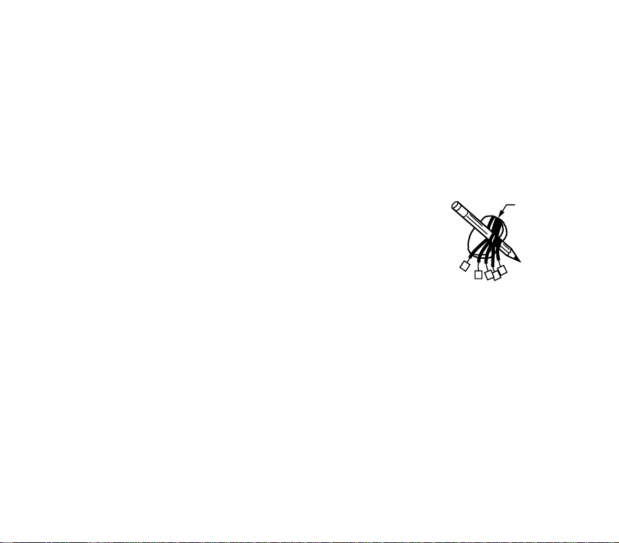
❑ Disconnect the wires from the old thermostat. As you disconnect each wire, attach the enclosed labels with the old
terminal designation. If there are only two wires, they do not need to be labeled. Wrap the wires around a pencil as
shown to keep them from falling back into the wall.
Special Installations
Read this section if you are replacing:
• Clock thermostat with separate wires for the clock.
• Thermostat with six or more wires connected to it.
• Thermostat in a heating only system with three wires.
Replacing a Clock Thermostat that has C or C1 Clock Terminals
If you are replacing a Honeywell Chronotherm®
Thermostat, you may find one or two
wires going to the C or C1 clock terminals on the Chronotherm wiring wallplate. Do not allow them to touch, or you can
damage the transformer. Disconnect the wires and wrap them separately using electrical tape. Do not wrap them
together. Place the wires where they will not interfere with the operation of the new thermostat. Record the colors and
terminal designation labels of the remaining wires.
Replacing a Thermostat that has Six or More Wires
If there are six or more wires (excluding clock wires attached to terminals), you probably have a variation of a
multistage heat pump or other multistage system. This thermostat is not compatible with multistage systems, so return
the product to the place of purchase. For information about which programmable thermostats will work with your
system, call Honeywell Customer Relations Center, at 1-800-468-1502.
Replacing a Thermostat that has Three Wires
If you have three wires for a heating only system and can operate the fan using the fan ON switch this thermostat
works with your system. However, some hot water (zoned) heating systems also have three wires. Your thermostat will
work only if you install an isolating relay on these systems. For details, call your local heating and/or cooling contractor.
WIRES THROUG
H
WALL OPENING
M5136
7 69-1642
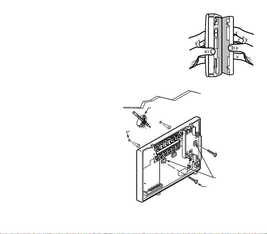
STEP 3. MOUNT THERMOSTAT WALLPLATE
❑ Separate the wallplate from the thermostat by placing your thumb or fingers
between the bottom of the wallplate and the thermostat, and pulling the
wallplate up and away from the thermostat. See illustration at right.
❑ Position the wallplate on the wall. Level the wallplate for appearance if desired.
Use a pencil to mark the two mounting holes that best fit the application.
❑ Remove the wallplate from the wall. Drill two 3/16 in. holes in wall (if drywall) as
shown. For materials such as plaster or wood, drill 7/32 in. holes where marked.
Gently, tap the (provided) anchors into the drilled holes until they are flush with
the wall.
❑ Reposition the wallplate over the holes. Pull the wires through the wiring
opening. Loosely insert mounting screws into each of the holes.
❑ Level the wallplate if desired. Thermostat functions properly when not level.
❑ Tighten mounting screws.
M16427
WIRES
THROUGH WALL
WALL
MOUNTING
HOLES
M15044
MOUNTING
SCREWS
WALL
ANCHORS (2)
69-1642 8
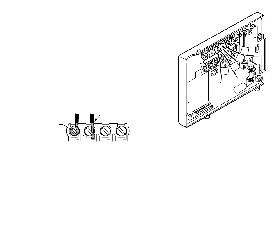
STEP 4. WIRE WALLPLATE TERMINALS
IMPORTANT
All wiring must comply with local codes and ordinances. If
unsure about household wiring procedures, call your local heat-
ing/air-conditioning contractor.
Refer to the labels you placed on the wires when you removed the old
thermostat (see illustration).
❑ Match the letter of your old thermostat wire with the corresponding
terminal letter on your new thermostat. Refer to Table 2.
❑ Remove the factory-installed jumper connecting terminals R and RC if
wires are connected to both of those terminals.
❑ For wiring diagrams, if needed, see pp 22-23.
❑ Loosen the terminal screws. Slip each wire beneath its matching
terminal. Wraparound and straight connections are both acceptable,
(see illustration). Tighten the terminals.
❑ Plug the hole in the wall with insulation to help prevent drafts from adversely affecting thermostat operation.
M16425
R
W
Y
G
M482
6
F
OR WRAPAROUND
I
NSERTION STRIP
7
/16 IN. (11 MM).
FOR STRAIGHT INSERTION
STRIP 5/16 IN. (8 MM).
 Loading...