


DB7110U Universal Heat Pump
Defrost Controller
INSTALLATION INSTRUCTIONS
APPLICATION
The DB7110U Universal Heat Pump Defrost Controller is a heat pump defrost control used in single stage heat pump appliances. This product replaces over 260 OEM and competitive controls and can be easily programmed to meet the requirements of virtually any single stage heat pump. See Table 2, “Compatibility Chart.,” on page 5.
FEATURES
The DB7110U provides:
•Universal defrost control for single stage heat pumps
•LED display for easy setup and configuration
•Small, square footprint for easier installation
•Demand and timed defrost modes
•System status and fault indication
•Selectable reversing delay to limit noise when going in and out of a defrost cycle
•Fault history for easy troubleshooting
MENU SETTING
DB7110U-DEFROST CONTROL
SYSTEM FAULT
M37637
Fig. 1. DB7110U1000.
SPECIFICATIONS
Electrical Ratings
Input Voltage: 24VAC, 60Hz
Max. Input Current: 200mA
Compressor Contactor: 1A @ 24VAC
Outdoor Fan:
1/2HP motor
5A full load, 30A locked rotor, 240VAC.
Aux Heat: 1A @ 24VAC
Reversing Valve: 1A @ 24VAC
All outputs rated for 100,000 operations.
All terminals except FAN-IN and FAN-OUT are NEC Class 2 low voltage.
Environmental Ratings
Operating Temperature Range: -40F to 150F
Humidity Limits: less than 95% (non-condensing)
INSTALLATION AND
CONFIGURATION
Overview
When Installing This Product…
1.Read these instructions carefully. Failure to follow instructions can damage the product or cause a hazardous condition.
2.Check ratings given in these instructions and on the product to make sure the product is suitable for your application.
3.Installer must be a trained, experienced service technician.
4.Use these instructions to check out the product operation after installation.
34-00032-01
DB7110U UNIVERSAL HEAT PUMP DEFROST CONTROLLER
 WARNING
Electrical Shock Hazard. Can cause severe injury, death or property damage.
Disconnect power supply before beginning installation to prevent electrical shock or equipment damage. More than one disconnect may be involved.
Control Location
1.Before removing the old control, make note of the wire connections to ensure the wires will be connected to the correct terminals of the DB7110U.
2.Mount DB7110U inside the junction box on the outdoor unit using the two included self-drilling sheet metal screws.
3.Use the control as a template to drill new mounting holes if necessary.
4.If the mounting tabs interfere with other components in the junction box, break/cut off the unused mounting tabs prior to tightening the mounting screws.
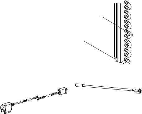
SENSOR
M37638
Fig. 3. Coil Sensor Mounting.
OUTDOOR AIR SENSOR LOCATION
Coil Sensor Location
M37663
Fig. 2. Coil Sensor.
1.The outdoor coil sensor must be used. Without the coil sensor, the DB7110U cannot determine when to defrost. The coil sensor included with the DB7110U replaces the existing defrost thermostat or coil sensor installed on the unit.
2.Place the sensor on the coil where the OEM sensor/thermostat was located. If replacing a defrost thermostat, note the original settings for proper adjustment of the termination and enable temperatures on the DB7110U. They are often marked with their open and close points. A thermostat marked L60-25F for example would correspond to a Termination Temperature of 60degF and an Enable Temperature of 35degF (60deg-25deg).
3.If the location of the OEM sensor/thermostat is inaccessible or difficult to access, place the new coil sensor on the coil loop nearest the expansion valve where refrigerant is entering the coil during the heating mode. This location gives the largest temperature difference between the air.
4.Ensure the coil sensor is clamped tightly to the coil. It may be desirable to add insulation to the sensor to yield more accurate readings, although this is generally not needed.
M37664
Fig. 4. Air Sensor.
1.The outdoor air sensor is optional. Using the outdoor air sensor will enable the DB7110U to implement a more advanced defrost algorithm that determines to defrost based on the relationship between coil and air temperatures. Without the air sensor, the DB7110U defrosts when the coil temperature is below the Enable Temperature for the Defrost Cycle Time. It is advisable to use the air sensor if possible as it may reduce the number of unnecessary defrosts that are common among defrost timers.
2.Mount the air sensor such that the capsule is hanging in air near the outdoor coil.
3.Do not locate the air sensor too close to the coil that sensor readings are influenced by it.
4.Do not mount the air sensor in direct sunlight.
5.The air sensor capsule should not be in contact with metal or some other material that may change its readings.
Wiring
 WARNING
Electrical Shock Hazard. Can cause severe injury, death, or property damage.
Disconnect power supply before beginning wiring to prevent electrical shock or equipment damage. More than one disconnect may be involved.
1.Make sure the wiring complies with all local codes and ordinances.
2.If the low voltage wiring is bare wire with no terminals, wire nut them to the included wiring pigtails. Do not crimp terminals to solid wire.
34-00032—01 |
2 |

DB7110U UNIVERSAL HEAT PUMP DEFROST CONTROLLER
3.Check the line voltage connections on the fan relay to ensure they are tight, in good connection, and more than 1/4" away from any part of the appliance enclosure.
4.Plug in the outdoor sensor (if used) and the coil sensor.
5.Reference the wiring diagrams in Figs. 5 to 8 to aide in proper appliance wiring.
Table 1. Class 2 Low Voltage Terminations,
24V 60Hz.
|
|
Name |
Function |
R (24V) |
24V Hot |
|
|
C (COM) |
24V Common |
|
|
W |
Aux/emergency heat request from |
|
thermostat – W requests will cause |
|
the AUX output to be energized. |
|
|
Y |
Compressor request from |
|
thermostat – Y requests will cause |
|
the COMPR and FAN terminals to be |
|
energized. |
|
|
O |
Reversing valve request from |
|
thermostat – controls the status of |
|
the RV output. |
|
|
HPC |
High pressure cutout/switch – these |
(2 Terminals) |
terminals must be shorted for |
|
compressor operation. Never |
|
bypass protective pressure |
|
switches. |
LPC |
High pressure cutout/switch – these |
(2 Terminals) |
terminals must be shorted for |
|
compressor operation. Never |
|
bypass protective pressure |
|
switches. |
AUX |
Output to auxiliary/emergency heat |
|
– energized during a defrost cycle or |
|
when requested by W input. |
|
|
COMPR |
Output to compressor contactor – |
(2 Terminals) |
energized by Y request. |
|
|
RV |
Output to reversing valve – |
(2 Terminals) |
energized by O input and as |
|
required by a defrost cycle. |
|
|
INDOOR |
DB7110U |
OUTDOOR |
|
EQUIPMENT |
EQUIPMENT |
||
|
|
FAN-OUT |
FAN |
|
|
L2 |
|
|
|
|
|
AUX |
|
FAN-IN |
L1 |
|
|
||
R |
|
RV |
REVERSING |
C |
|
VALVE |
|
|
|
|
|
|
|
COMPR |
CONTACTOR |
O/B |
|
|
|
|
|
|
|
W |
|
HPC |
HIGH |
|
PRESSURE |
||
|
|
||
Y |
|
|
SWITCH |
|
|
|
|
|
|
LPC |
LOW |
|
|
PRESSURE |
|
|
COIL |
AIR |
SWITCH |
|
|
||
|
|
|
AIR |
|
|
|
SENSOR |
|
|
|
(OPTIONAL) |
|
|
|
COIL |
|
|
|
SENSOR |
|
|
|
M37756 |
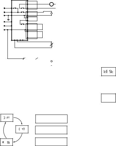
Fig. 5. Wiring diagram with pressure switches connected to defrost control.
INDOOR |
DB7110U |
OUTDOOR |
|
EQUIPMENT |
|||
EQUIPMENT |
|
|
FAN |
|
|
FAN-OUT |
L2 |
|
|
|
|
AUX |
|
FAN-IN |
L1 |
|
|
||
R |
|
RV |
REVERSING |
C |
|
VALVE |
|
|
|
|
|
|
|
COMPR |
CONTACTOR |
O/B |
|
|
|
|
|
|
|
W |
|
HPC |
HIGH |
|
PRESSURE |
||
|
|
||
Y |
|
|
SWITCH |
|
|
|
|
|
|
LPC |
|
|
COIL |
AIR |
|
|
|
|
AIR |
|
|
|
SENSOR |
|
|
|
(OPTIONAL) |
|
|
|
COIL |
|
|
|
SENSOR |
|
|
|
M37757 |
Fig. 6. Wiring diagram for systems with no low pressure switch.
INDOOR |
|
|
OUTDOOR |
EQUIPMENT |
DB7110U |
EQUIPMENT |
|
|
|
FAN-OUT |
FAN |
|
|
L2 |
|
|
|
FAN-IN |
|
AUX |
|
L1 |
|
|
|
||
R |
|
RV |
REVERSING |
C |
|
VALVE |
|
|
|
|
|
|
|
COMPR |
HIGH |
|
|
PRESSURE |
|
O/B |
|
|
|
|
|
SWITCH |
|
|
|
|
|
W |
|
HPC |
LOW |
|
|
||
|
|
PRESSURE |
|
Y |
|
|
|
|
|
SWITCH |
|
|
|
|
|
|
|
LPC |
CONTACTOR |
|
|
|
|
|
COIL |
AIR |
|
|
|
IF THE PRESSURE SWITCH(ES) ARE IN SERIES |
|
|
|
WITH THE CONTACTOR, JUMPER THE |
|
|
|
ONBOARD CONNECTIONS. DO NOT BYPASS |
|
|
|
ANY PROTECTIVE PRESSURE SWITCHES. |
|
|
|
|
AIR |
|
|
|
SENSOR |
|
|
|
(OPTIONAL) |
|
|
|
COIL |
|
|
|
SENSOR |
|
|
|
M37758 |
Fig. 7. Wiring diagram for systems with pressure switches in series with the contactor and no connection to the defrost control.
3 |
34-00032—01 |
DB7110U UNIVERSAL HEAT PUMP DEFROST CONTROLLER
INDOOR |
|
|
OUTDOOR |
EQUIPMENT |
DB7110U |
EQUIPMENT |
|
|
|
||
|
|
FAN-OUT |
FAN |
|
|
L2 |
|
|
|
|
|
AUX |
|
FAN-IN |
L1 |
|
|
||
R |
|
RV |
REVERSING |
C |
|
VALVE |
|
|
|
|
|
|
|
COMPR |
|
O/B |
|
|
IF THE PRESSURE |
|
|
|
|
W |
|
HPC |
SWITCH(ES) ARE IN SERIES |
|
|
WITH THE CONTACTOR, |
|
|
|
|
|
Y |
|
|
JUMPER THE ONBOARD |
|
|
|
CONNECTIONS. |
|
|
LPC |
DO NOT BYPASS ANY |
|
|
|
PROTECTIVE PRESSURE |
|
COIL |
AIR |
SWITCHES. |
|
|
|
COIL |
|
|
|
SENSOR |
WHEN THE COMPRESSOR CONTACTOR IS POWERED DIRECTLY FROM THE Y TERMINAL, SET THE REVERSING DELAY AND SHORT CYCLE DELAY TO 0.
|
|
|
|
|
|
|
|
HIGH |
LOW |
|
|
CONTACTOR |
|||
PRESSURE |
PRESSURE |
|
|
|
|||
SWITCH |
SWITCH |
|
|
|
M37759 |
||
|
|
|
|||||
Fig. 8. Wiring diagram for simple timer applications.
CONFIGURATION
1.Connect power.
2.On power up the display will briefly flash the software version of the DB7110U and then begin cycling between the normal operating screens showing the current mode and the values of the two temperature sensors. Note that there is brief startup delay following power up where compressor operation is prohibited.
CURRENT MODE OF OPERATION
OFF, HEAT, COOL, DELAY, ETC.
OUTDOOR COIL TEMPERATURE
DEGREES FAHRENHEIT
OUTDOOR AIR TEMPERATURE
DEGREES FAHRENHEIT
M37640
Fig. 9.
The displayed coil and air temperature readings can be very useful for optimizing and troubleshooting defrost performance.
3.There are several configurable options to optimize defrost performance. See “User Interface” on page 7 for a detailed description of each
parameter/screen. Press the select (o) button advance through the various screens and and buttons to adjust the various parameters. Table 4 below describes each parameter.
CHECKOUT
1.After the startup delay has expired, generate a request for heat by shorting R to Y (and R to O if configured as a “B” system, reversing valve energized in heating mode).
2.Verify the compressor, fan, and reversing valve (if applicable) are energized.
3.Press and hold the button until “tESt” appears on the display as shown below.
M37641
Fig. 10.
4.Verify the unit enters defrost mode
de Fr
M37642
Fig. 11.
The reversing valve will change states and the aux heat will be energized. A few moments later the fan will be turned off. If Reversing Delay is enabled, the compressor will be turned off for the selected time, and then turn back on to reduce noise.
The DB7110U will remain in defrost for at least one minute. After one minute has elapsed, the DB7110U will exit defrost after the coil temperature has risen above the termination temperature or after the selected defrost time, whichever comes first.
Test mode can be terminated at any time by pressing and holding the button again.
34-00032—01 |
4 |
 Loading...