


CT87A,B,J Round® Thermostat
LOW VOLTAGE (15 TO 30 VAC), THERMOSTAT AND MOUNTING HARDWARE
Installation Instructions
1Verify that you have the correct thermostat
Using the compatibility chart below, verify that you purchased the correct CT87Thermostat for your heating/cooling system. If you are unsure which model is right for your system, visit www.honeywell.com/ yourhome or call Honeywell Customer Care at 1-800-468-1502.
|
Compatible with: |
||
Heating/Cooling system |
CT87A |
CT87B |
CT87J |
|
|
|
|
Heating only: Gas or oil fueled warm air, steam, or hot |
Yes |
Yes |
No |
water heat |
|
|
|
Cooling only: Electric air conditioning |
Yes* |
Yes |
Yes |
Heating and cooling: Gas or oil fueled warm air, |
No |
Yes |
No |
steam, or hot water heat with electric air conditioning |
|
|
|
Single stage heat pump: Outdoor heating/cooling unit |
No |
No |
Yes |
(compressor) with no auxiliary or backup heat. |
|
|
|
Electric heat furnace with or without cooling: |
No |
No |
Yes |
Electric baseboard: Electric heating strips located just |
No |
No |
No |
above the floor, usually 120-240 volts |
|
|
|
|
|
|
|
Multistage: A conventional system with more than one |
No |
No |
No |
stage, or an outdoor heating/cooling unit (compressor) |
|
|
|
with auxiliary or backup heat. |
|
|
|
|
|
|
|
* CT87A is compatible with 2-wire cooling-only systems. |
|
|
|
® U.S. Registered Trademark |
|
Copyright © 2002 Honeywell |
|
All Rights Reserved |
69-0274-6 |
|
CT87A,B,J ROUND® THERMOSTAT
2Prepare for installation
1.Carefully unpack your new thermostat; rough handling may affect its accuracy. Save your receipt and identify the following parts:
•CT87 Thermostat
•Screws: two 1-in. sheet metal screws, two 1/2-in. binding head screws, and two 1/4-in. round head screws
•Wallplate (CT87A) or subbase (CT87B, CT87J)
•Cover ring (select models only). Necessary if installing on an outlet box. Optional if installing directly on the wall; can be used to hide wall marks.
•These Installation Instructions and the Installation Quick Guide.
•Wiring labels
2.Gather these tools:
Required Tools |
|
Optional Tools |
|
|
|
|
|
• |
Flat blade |
• Hand or power drill with 1/16-in. drill bit |
|
• |
screwdriver |
• |
Wire cutter/stripper or sharp knife |
Spirit level |
• |
Pencil |
|
|
|
|
|
3Remove the old thermostat
1.Turn off power to the heating/cooling system at the main fuse/circuit breaker panel.
2.Remove the cover of your old thermostat. You may need to unscrew the cover if it is locked on.
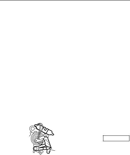
3.Locate the heat anticipator adjustment scale and lever on the old thermostat (Fig. 1).
Fig. 1. Mercury switch location.
 MERCURY
SWITCH
 OLD THERMOSTAT
ANTICIPATOR
SCALE
LEVER |
|
TYPICAL LOCATION OF A |
|
MERCURY SWITCH IN |
|
A THERMOSTAT |
M20206 |
In the box below, record the number that the adjustment lever points to. This is the current (amp) rating of your heating system.
Current setting:
If you cannot find the heat anticipator setting on the old thermostat, you can use a standard setting for your type of system when you reach Step 8 of this installation.
4.Unscrew and remove the old thermostat wallplate from the wall, but do not disconnect the wires.
69-0274-6 |
2 |

CT87A,B,J ROUND® THERMOSTAT
5.Label the wires using the wiring labels that came with the CT87. Identify each wire using the letter of the terminal on the old thermostat (Fig. 2). Do not label the wires by color.
6.Disconnect the wires from the old thermostat and wrap them around a pencil to keep them from falling back into the wall (Fig. 3).
Fig. 2. Labeling wires.
M19086
Fig. 3. Wrapping wires.
 MERCURY NOTICE
WIRES THROUGH WALL OPENING
If this thermostat is replacing a |
|
control that contains mercury in a |
|
sealed tube, do not place your old |
|
control in the trash. Contact your |
M20133 |
local waste management authority |
|
for instructions regarding recycling and the proper disposal of this control, or of an old control containing mercury in a sealed tube.
4Install the cover ring and wallplate or subbase
If installing on the wall
Refer to Fig. 4 as you work.
Fig. 4. Installing wallplate/subbase on the wall (wallplate shown).
COVER RING
WALLPLATE
|
THERMOSTAT |
|
WIRING OPENING |
NO. 4 X 1 INCH |
M20188 |
SHEET METAL SCREWS (2) |
3 |
69-0274-6 |
CT87A,B,J ROUND® THERMOSTAT
1.If using the cover ring: Position the cover ring against the wall so that the arrow in the middle of the cover ring is pointing up.
2.Position the wallplate or subbase.
•If using cover ring: Place the wallplate/subbase over the cover ring. Rotate the wallplate/subbase until the wiring openings are aligned and the two screw holes on the left and right side of the wallplate/subbase align with the screw holes on the cover ring. You will be inserting screws through these holes into the wall.
•If attaching wallplate directly to the wall: Position so that the UP indicator on the wallplate is on top.
•If attaching subbase directly to the wall: Position so that the fan and heating/cooling switches are on the top.
3.Use a pencil to mark the center of the screw holes on the left and right sides of the wallplate or subbase.
4.Remove the wallplate/subbase and cover ring, and drill two 1/16-in. holes at the locations you marked.
5.Reposition the cover ring (if used) and wallplate/subbase over the holes, pull the wires through the wiring opening, and loosely insert the two 1-in. screws into the drilled holes.
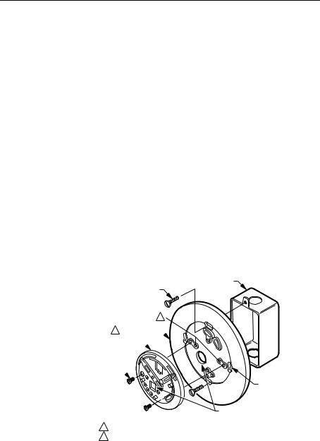
If installing on an outlet box
Refer to Fig. 5 as you work.
Fig. 5. Installing wallplate/subbase on an outlet box (subbase shown).
1/2 IN. BINDING |
OUTLET BOX |
|
|
HEAD SCREW (2) |
|
1
2 COVER RING  SUBBASE
1/4 IN.
ROUND
HEAD SCREW (2)
A
THERMOSTAT
WIRING HOLE
1THE TWO INNER HOLES ARE USED WITH WALLPLATE.
2IF OUTLET BOX IS HORIZONTAL, MOUNT COVER RING IN POSITION SHOWN, BUT FASTEN WITH SCREWS THROUGH "A".
M20187
69-0274-6 |
4 |
 Loading...