


DM855

OPERATING MANUAL
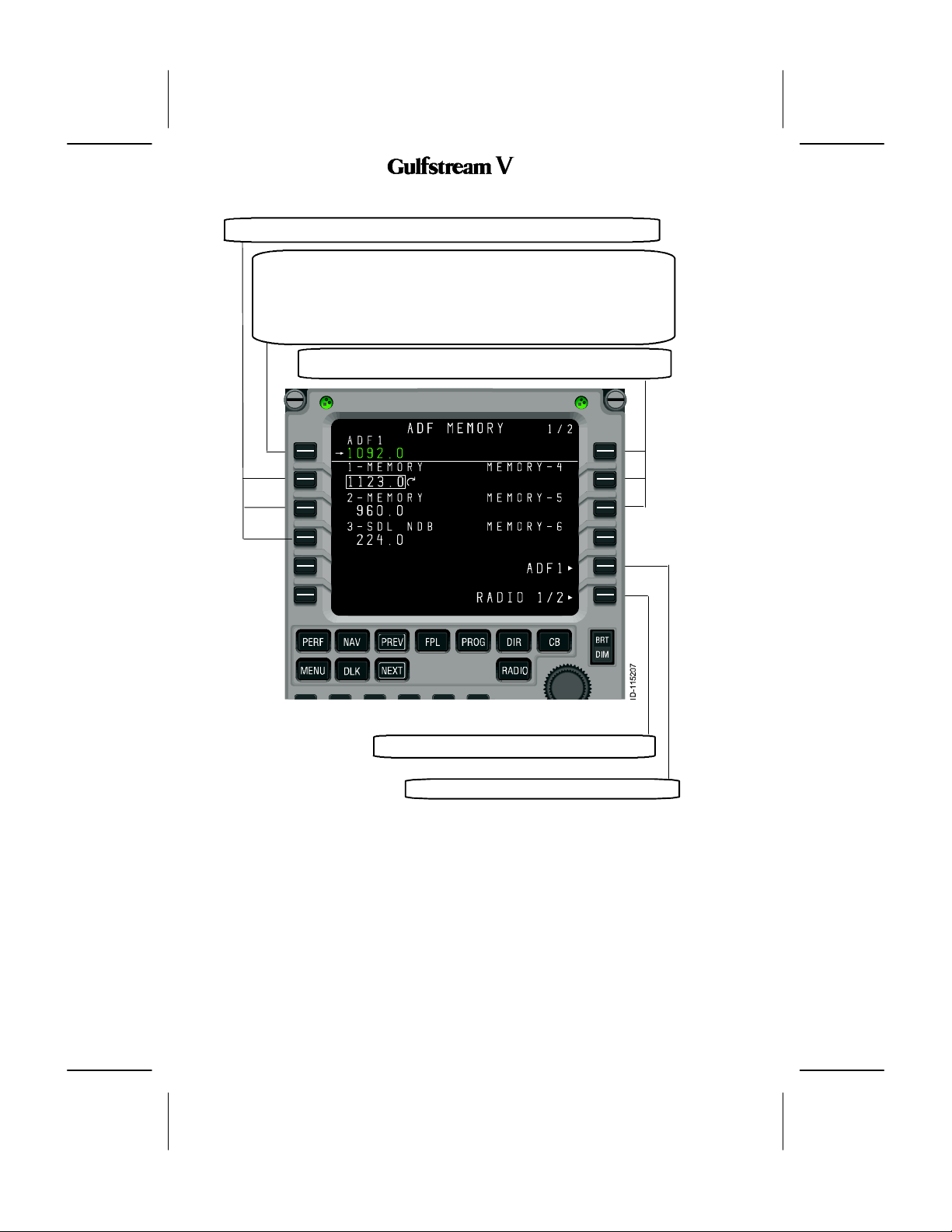
1. ADF Memory
As with the other radio types, the radio tuning function supports 12 ADF memories displayed
on two pages. In addition to entering or dialing--in frequencies for each memory, a text label
of up to 8 characters may be entered for each stored frequency. The default label for each
memory is ”MEMORY”, a dash, and the memory number, with the memory number always
on the outboard edge of the display. The ADF Memory page is described below.
Labels are entered by typing into thescratchpad andpushing the LSK adjacent to the desired
frequency. If the radio tuning function determines that the entry is a valid frequency for the
radio, the entry is accepted into the frequency field. If not, the entry is considered a label and
is entered into the label field above the frequency. A label can be replaced by making another
scratchpad entry into a memory field, or by pushing the DEL key. Pushing the DEL key
places the text ”DELETE” in the scratchpad and, when entered on a memory field, deletes
the associated text label, returning it to the default. If the DEL key is used on a memory where
there is no user--entered label, the frequency is deleted from memory.
Access to the ADF MEMORY 2/2 page is via the NEXT and PREV function keys.
DIGITAL AUTOMATIC FLIGHT CONTROL SYSTEMS
2B-09-00
Page 39
Nov 15/02
OPERATING MANUAL
These sections display the ADF memories 1--3 (7--9 on ADF MEMORY 2/2).
This section displays and controls the Active ADF frequency on the
selected radio (the field title will reflect which radio was selected).
Pushing LSK 1L copies the field containing the format cursor into the
active frequency and moves the previously active frequency into the
preset field (not shown on this page). A scratchpad entry into the field
replaces the preset frequency with the previous active frequency.
These sections display the ADF memories 4--6 (10--12 on ADF
MEMORY 2/2).
2B-09-00
Page 40
Nov 15/02
Pushing this LSK displays the RADIO 2/2 page.
Pushing this LSK displays ADF detail page.
DIGITAL AUTOMATIC FLIGHT CONTROL SYSTEMS
OPERATING MANUAL
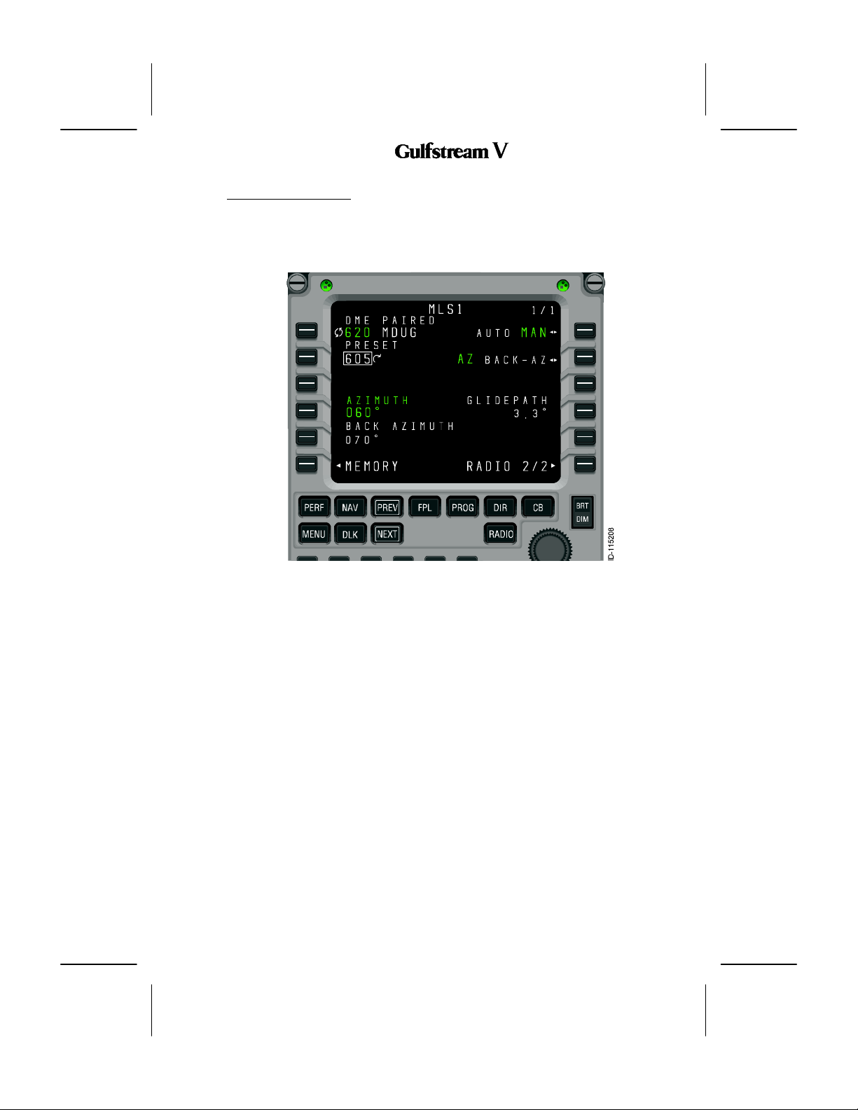
2B--09--70:
The MLS page, shown in Figure 43, shows the currently tuned procedure and a preset,
azimuth and back--azimuth, and glidepath angle, and allows setting of the operating mode
(automatic/manual) and azimuth selection (azimuth or back-- azimuth). It also provides
access to the MLS memory pages.
MLS1 PAGE
Figure 43
Unlike the detail pages for the other radios, the MLS page does not support the fast memory
tuning operation in field 3L.
DIGITAL AUTOMATIC FLIGHT CONTROL SYSTEMS
2B-09-00
Nov 15/02
Page 41

OPERATING MANUAL
1. MLS Memory Pages
The MLS memory pages, FINISH THIS SECTION
Figure 44
2B-09-00
Page 42
Nov 15/02
DIGITAL AUTOMATIC FLIGHT CONTROL SYSTEMS
OPERATING MANUAL
2B--09--80:
The MCDU radio tuning function communicates with the radio units using a bi-- directional
protocol. The radio tuning function expects to receive an acknowledgement when the radio
is successful in completing each tuning command.
A typical interaction begins with the user entering or dialing in a new frequency for a radio.
The MCDU sends the appropriate tuning command to the specified radio and awaits
confirmation. If no confirmation is received within the timeout period, the frequency display
on the page is changed to amber and a scratchpad message is issued as shown in Figure
45).
RADIO INTERACTIONS
Figure 45
The pilot can attempt to tune the radio again, in the event that the fault was transient or has
been cleared by crew action. This is also important in the event that the radio is receiving the
command and is, in fact, tuning the radio, but is unable to respond to the MCDU.
DIGITAL AUTOMATIC FLIGHT CONTROL SYSTEMS
2B-09-00
Nov 15/02
Page 43
OPERATING MANUAL
2B--09--90:
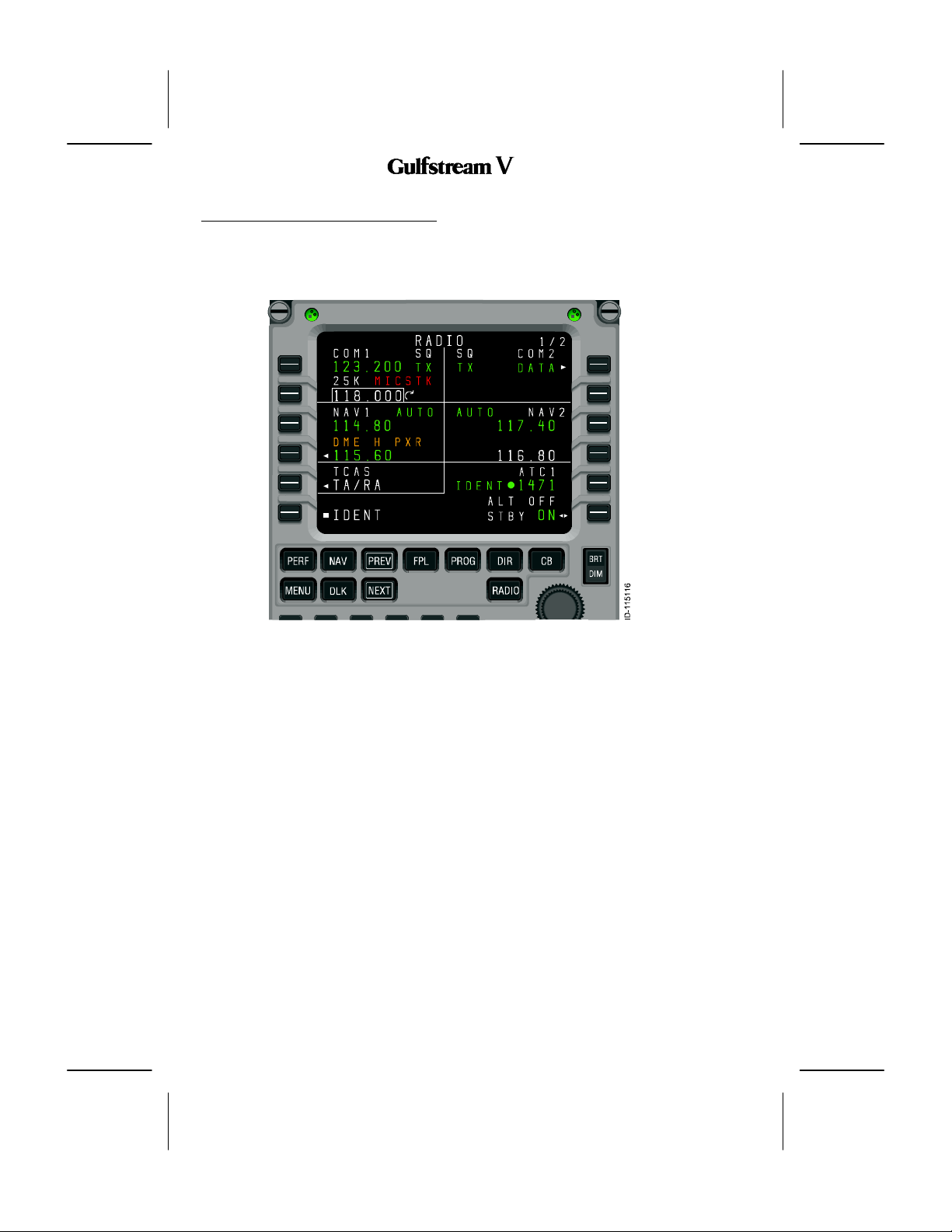
1. RADIO 1/2 A nnunciations
A variety of annunciations appear on the radio tuning pages, many of which are shown in
Figure 46.
ANNUNCIATION MESSAGES
Figure 46
2B-09-00
Page 44
Nov 15/02
DIGITAL AUTOMATIC FLIGHT CONTROL SYSTEMS
OPERATING MANUAL
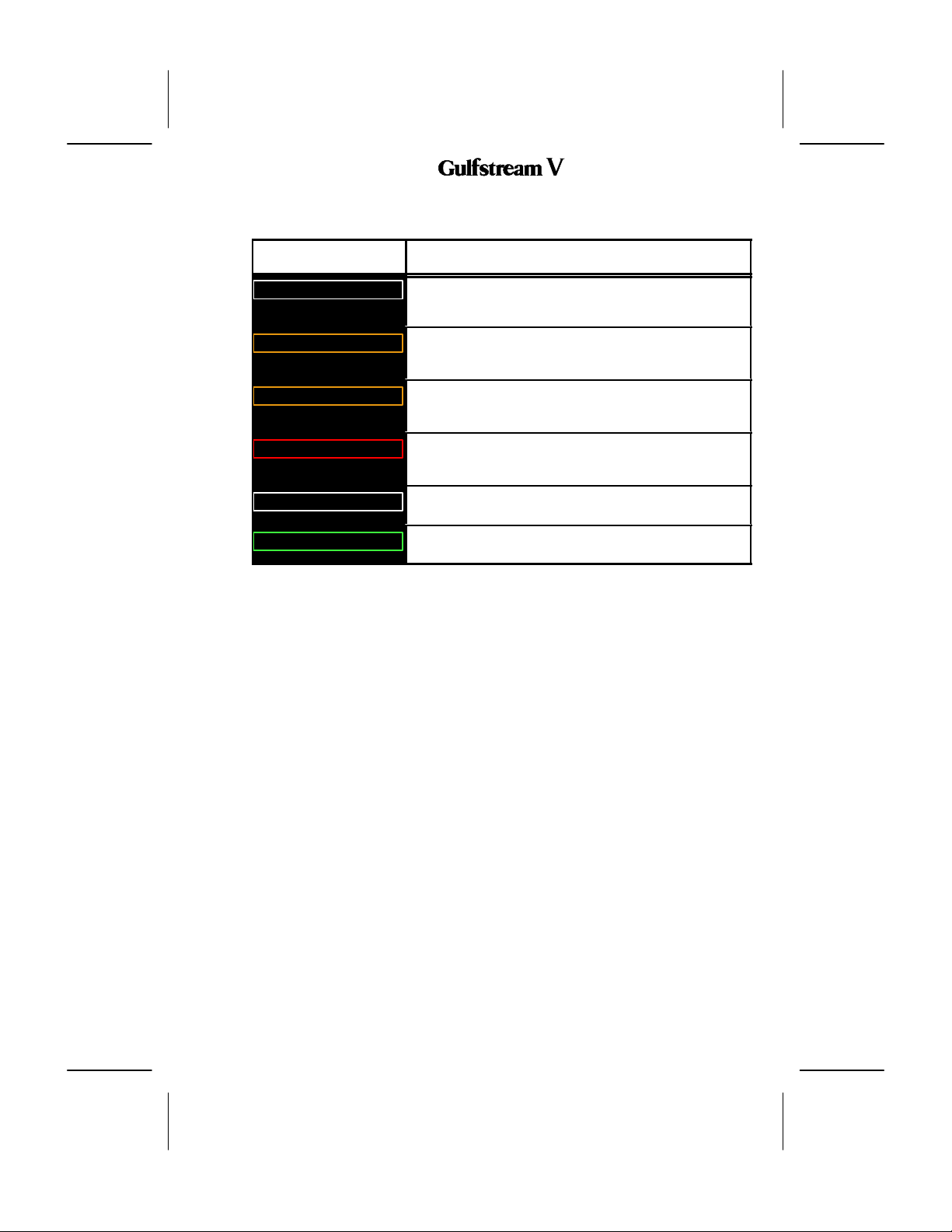
Table 33 describes the annunciators on RADIO 1/2.
Annunciator Description
25K
DME H xxx
IHBT
MICSTK
SQ
TX
Indicates that the associated VHF COM radio is set to 25KHz
frequency spacing. When not present, the radio is tuning with
8.33KHz frequency spacing.
This alert Indicates that the VHF navigation radio is tuning the
corresponding DME receiver independently of the primary
navigation frequency.
This annunciator Indicates that tuning of the radio is inhibited,
usually from a remote source (such as an emergency tuning
function).
Indicates that the microphone button on the radio has been
down long enough that the radio has identified it as ”stuck” in the
transmit position.
This annunciator Indicates that the squelch feature for the radio
is active.
This annunciator Indicates that the radio is currently
transmitting.
RADIO 1/2 Annunciator Descriptions
Table 33
DIGITAL AUTOMATIC FLIGHT CONTROL SYSTEMS
2B-09-00
Page 45
Nov 15/02
OPERATING MANUAL
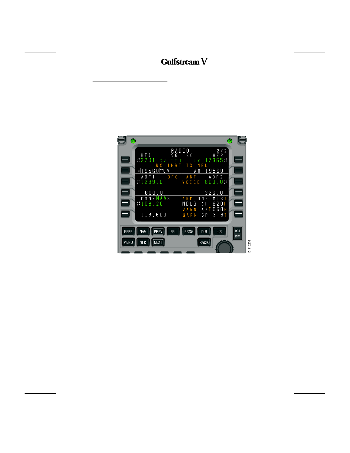
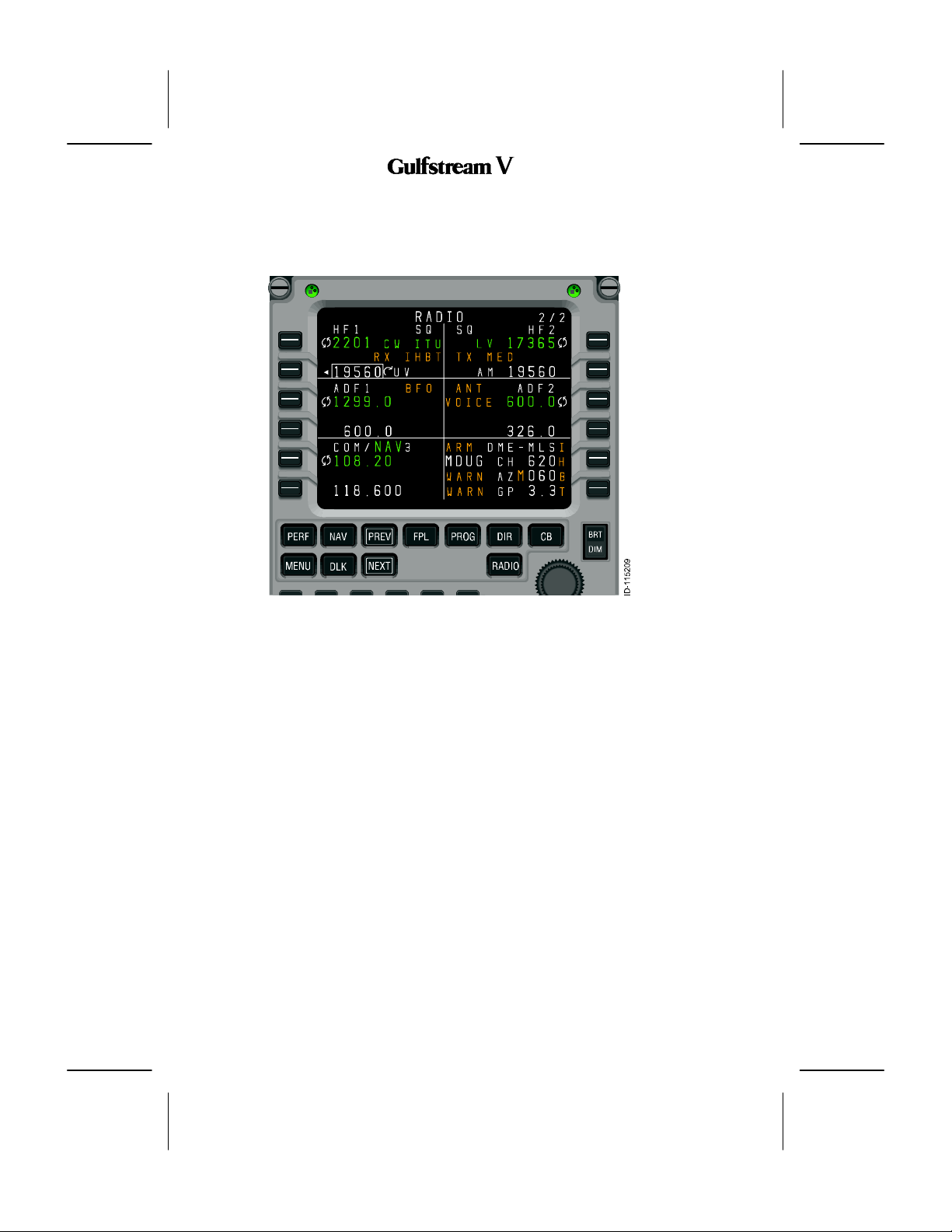
2. RADIO 2/2 A nnunciations
A variety of annunciations appear on the radio tuning pages, many of which are shown in in
Figure 46.
Figure 47
2B-09-00
Page 46
Nov 15/02
DIGITAL AUTOMATIC FLIGHT CONTROL SYSTEMS
OPERATING MANUAL
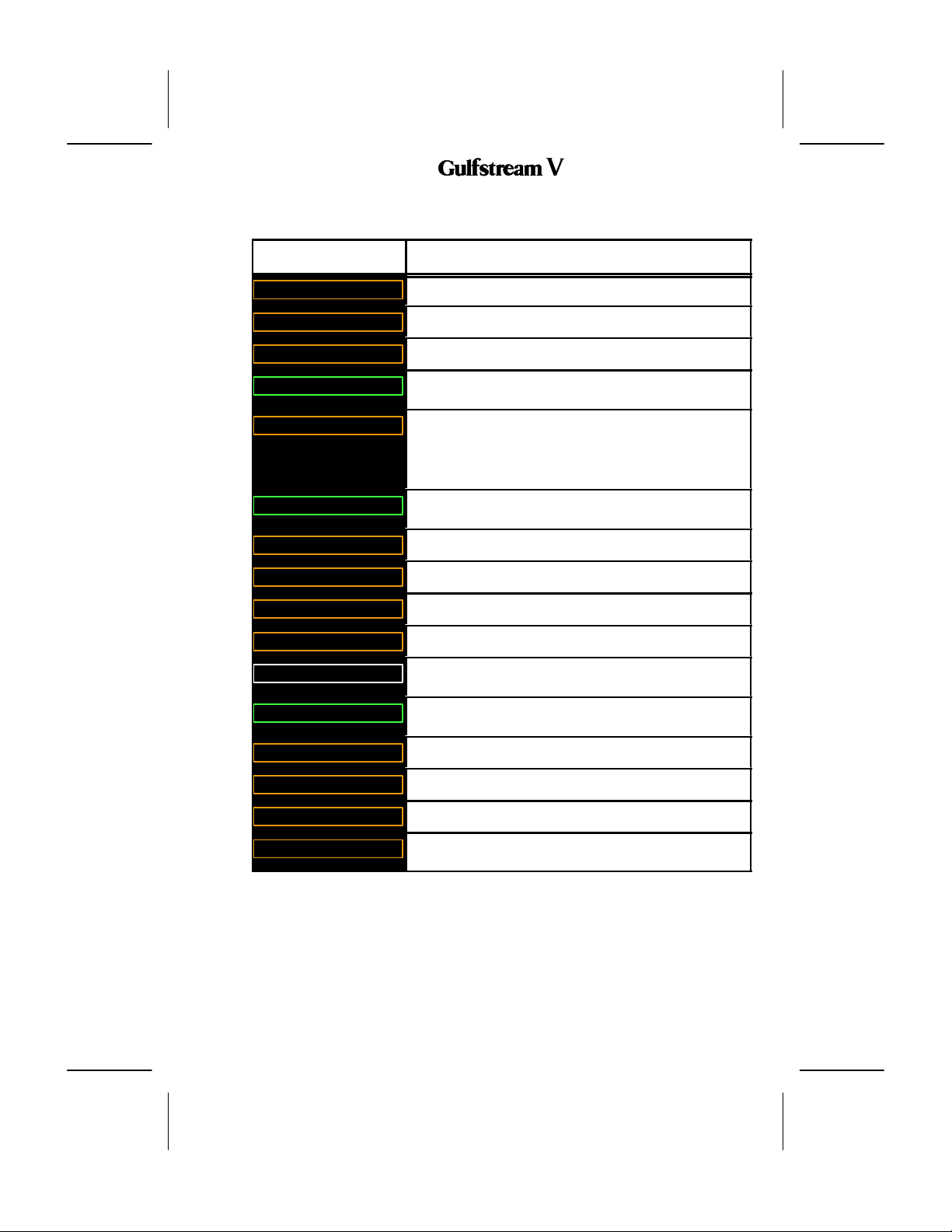
Table 34 describes the annunciators on RADIO 2/2.
Annunciator Description
ANT
ARM
BFO
CW
IHBT
ITU
LO
M
MED
RX
SQ
TX
TX LO
The ADF radio is in antenna mode.
An MLS procedure is armed.
The ADF radio is operating in BFO mode.
This annunciator Indicates that the radio is currently
transmitting.
Indicates that tuning of the radio is inhibited, usually from a
remote source (such as an emergency tuning function). In the
case of two HF radios sharing a single antenna, transmitting
and/or receivingmay be inhibited periodically when the otherHF
radio has recently performed a transmit operation.
This annunciator Indicates that the radio is currently
transmitting.
The radio is set to low squelch.
An MLS parameter has been set manually.
The radio is set to medium squelch.
Indicates that the radio is currently receiving.
This annunciator Indicates that the squelch feature for the radio
is active.
This annunciator Indicates that the radio is currently
transmitting.
The radio is transmitting with low power.
TX MED
VOICE
WARN
DIGITAL AUTOMATIC FLIGHT CONTROL SYSTEMS
The radio is transmitting with medium power.
The ADF radio is in voice mode.
There is a problem withthe azimuth, back--azimuth, or glidepath
data for the MLS procedure.
RADIO 2/2 Annunciator Descriptions
Table 34
2B-09-00
Page 47
Nov 15/02
OPERATING MANUAL
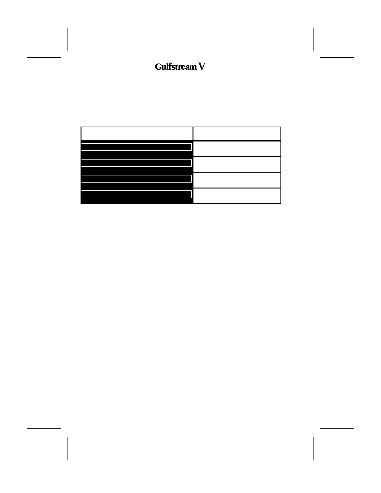
3. Scratchpad Messages
The scratchpad messages described in table , may be generated by the radio tuning
function. In the process of implementing this function, other required messages may come
to light.
Table 34 describes the annunciators on RADIO 2/2.
Annunciator Description
DELETE
INVALID ENTRY
SQNO RESPONSE FROM RADIO
STUCK MICROPHONE
RADIO 2/2 Annunciator Descriptions
Table 35
This annunciator Indicates that the
value in the scratchpad is deleted.
This annunciator Indicates that the
entry in the scratchpad is invalid.
This annunciator Indicates that the
squelch noise is coming from the radio.
This annunciator Indicates that the
microphone key is stuck.
2B-09-00
Page 48
Nov 15/02
DIGITAL AUTOMATIC FLIGHT CONTROL SYSTEMS
 Loading...