


 Loading...
Voyager 1602g
Wireless Area-Imaging Pocket Scanner
User’s Guide

Disclaimer
Honeywell International Inc. (“HII”) reserves the right to make changes in specifications and other information contained in this document without prior notice, and the reader should in all cases consult HII to determine whether any such changes have been made. The information in this publication does not represent a commitment on the part of HII.
HII shall not be liable for technical or editorial errors or omissions contained herein; nor for incidental or consequential damages resulting from the furnishing, performance, or use of this material. HII disclaims all responsibility for the selection and use of software and/or hardware to achieve intended results.
This document contains proprietary information that is protected by copyright. All rights are reserved. No part of this document may be photocopied, reproduced, or translated into another language without the prior written consent of HII.
Copyright 2015-2016 Honeywell International Inc. All rights reserved.
Web Address: www.honeywellaidc.com
Microsoft® Windows®, Windows NT®, Windows 2000, Windows ME, Windows XP, and the Windows logo are trademarks or registered trademarks of Microsoft Corporation.
The Bluetooth® word mark and logos are owned by Bluetooth SIG, Inc.
Apple is a trademark of Apple Inc., registered in the U.S. and other countries.
Other product names or marks mentioned in this document may be trademarks or registered trademarks of other companies and are the property of their respective owners.
For patent information, refer to www.hsmpats.com.

Table of Contents
Customer Support
Technical Assistance ............................................................................................................ |
ix |
Product Service and Repair .................................................................................................. |
ix |
Limited Warranty ................................................................................................................... |
ix |
Send Feedback ..................................................................................................................... |
ix |
Chapter 1 - Getting Started |
|
About This Manual ............................................................................................................... |
1-1 |
Unpacking Your Device ....................................................................................................... |
1-1 |
Charging the Scanner Battery.............................................................................................. |
1-1 |
Charging with a Power Supply ....................................................................................... |
1-1 |
Charging with a PC ........................................................................................................ |
1-2 |
Battery Charge Indicator ................................................................................................ |
1-2 |
Pairing the Scanner with Bluetooth® Devices ...................................................................... |
1-3 |
Pairing the Scanner with an Apple Device Using SPP................................................... |
1-4 |
Reading Techniques ............................................................................................................ |
1-5 |
Menu Bar Code Security Settings........................................................................................ |
1-5 |
Setting Custom Defaults ...................................................................................................... |
1-6 |
Resetting the Custom Defaults ............................................................................................ |
1-6 |
Chapter 2 - Programming the Interface |
|
Introduction .......................................................................................................................... |
2-1 |
Keyboard Country Layout .................................................................................................... |
2-1 |
Keyboard Style..................................................................................................................... |
2-8 |
Keyboard Conversion .......................................................................................................... |
2-9 |
Control Character Output................................................................................................... |
2-10 |
Keyboard Modifiers ............................................................................................................ |
2-10 |
Programming an Interface for an Access Point ................................................................. |
2-12 |
Keyboard Wedge ......................................................................................................... |
2-12 |
Laptop Direct Connect ................................................................................................. |
2-12 |
RS232 Serial Port ........................................................................................................ |
2-12 |
RS485 .......................................................................................................................... |
2-13 |
USB IBM SurePos........................................................................................................ |
2-14 |
USB PC or Macintosh Keyboard.................................................................................. |
2-14 |
USB HID....................................................................................................................... |
2-15 |
USB Serial.................................................................................................................... |
2-15 |
Remote MasterMind™ for USB.................................................................................... |
2-15 |
Gilbarco® Terminal Default Settings ............................................................................ |
2-16 |
Honeywell Bioptic Aux Port Configuration.................................................................... |
2-16 |
Datalogic™ Magellan® Aux Port Configuration............................................................ |
2-16 |
NCR Bioptic Aux Port Configuration ............................................................................ |
2-17 |
Wincor Nixdorf Terminal Default Settings .................................................................... |
2-17 |
Wincor Nixdorf Beetle™ Terminal Default Settings ..................................................... |
2-17 |
Wincor Nixdorf RS232 Mode A .................................................................................... |
2-18 |
RS232 Modifiers........................................................................................................... |
2-18 |
Scanner to Bioptic Communication .............................................................................. |
2-22 |
i

Programming the VG1602 Corded Interface ..................................................................... |
2-23 |
Setting the VG1602 Corded Interface.......................................................................... |
2-23 |
Corded USB PC or Macintosh Keyboard..................................................................... |
2-23 |
Corded USB HID POS................................................................................................. |
2-23 |
Corded USB Serial ...................................................................................................... |
2-24 |
Chapter 3 - Wireless System Operation |
|
Bluetooth Settings ............................................................................................................... |
3-1 |
Bluetooth HID Keyboard Disconnect ............................................................................. |
3-1 |
Bluetooth Serial Port - PCs/Laptops .............................................................................. |
3-1 |
PDAs/Mobility Systems Devices.................................................................................... |
3-1 |
Changing the Scanner’s Bluetooth PIN Code................................................................ |
3-1 |
Minimizing Bluetooth/ISM Band Network Activity ................................................................ |
3-2 |
Auto Reconnect Mode ................................................................................................... |
3-2 |
Maximum Link Attempts ................................................................................................ |
3-2 |
Relink Time-Out............................................................................................................. |
3-3 |
Bluetooth/ISM Network Activity Examples..................................................................... |
3-3 |
Communication Between the Scanner and the Host........................................................... |
3-4 |
Programming the Scanner and Host ................................................................................... |
3-4 |
RF (Radio Frequency) Module Operation ........................................................................... |
3-4 |
System Conditions............................................................................................................... |
3-4 |
Scanner Is Out of Range ............................................................................................... |
3-4 |
Scanner Is Moved Back Into Range .............................................................................. |
3-4 |
Out of Range and Back into Range with Batch Mode On.............................................. |
3-4 |
About the Battery................................................................................................................. |
3-4 |
Charging Information ..................................................................................................... |
3-5 |
Battery Recommendations ............................................................................................ |
3-5 |
Proper Disposal of the Battery....................................................................................... |
3-5 |
Beeper and LED Sequences and Meaning ......................................................................... |
3-5 |
Scan LED Sequences and Meaning.............................................................................. |
3-6 |
Low Battery Indicator ..................................................................................................... |
3-6 |
Reset Scanner..................................................................................................................... |
3-6 |
Scanner Report ................................................................................................................... |
3-6 |
Scanner Address ................................................................................................................. |
3-7 |
Linked Modes ...................................................................................................................... |
3-7 |
Locked Link Mode - Single Scanner .............................................................................. |
3-7 |
Open Link Mode - Single Scanner................................................................................. |
3-7 |
Unlinking the Scanner.................................................................................................... |
3-7 |
Override Locked Scanner .............................................................................................. |
3-8 |
Out-of-Range Alarm ............................................................................................................ |
3-8 |
Alarm Sound Type ......................................................................................................... |
3-8 |
Scanner Idle Alarm .............................................................................................................. |
3-9 |
Scanner Power Time-Out Timer.......................................................................................... |
3-9 |
Flexible Power Management ............................................................................................. |
3-10 |
Multiple Scanner Operation ............................................................................................... |
3-10 |
Scanner Name................................................................................................................... |
3-10 |
Application Work Groups................................................................................................... |
3-12 |
Application Work Group Selection ............................................................................... |
3-12 |
ii

Resetting the Factory Defaults: All Application Work Groups ........................................... |
3-13 |
Resetting the Custom Defaults: All Application Work Groups ........................................... |
3-13 |
Access Point Operations ................................................................................................... |
3-13 |
Linking the Scanner to an Access Point ...................................................................... |
3-13 |
Disconnect from Host and Connect to an Access Point .............................................. |
3-14 |
Replacing a Linked Scanner........................................................................................ |
3-14 |
Access Point LED Sequences and Meaning ..................................................................... |
3-15 |
Access Point Address........................................................................................................ |
3-15 |
Paging ............................................................................................................................... |
3-15 |
Paging Mode................................................................................................................ |
3-15 |
Paging Pitch................................................................................................................. |
3-15 |
Batch Mode ....................................................................................................................... |
3-16 |
Batch Mode Beep ........................................................................................................ |
3-17 |
Batch Mode Storage .................................................................................................... |
3-17 |
Batch Mode Quantity ................................................................................................... |
3-17 |
Batch Mode Output Order............................................................................................ |
3-19 |
Total Records .............................................................................................................. |
3-19 |
Delete Last Code ......................................................................................................... |
3-20 |
Clear All Codes............................................................................................................ |
3-20 |
Transmit Records to Host ............................................................................................ |
3-20 |
Batch Mode Transmit Delay ........................................................................................ |
3-20 |
Host Acknowledgment....................................................................................................... |
3-21 |
Host ACK Timeout ....................................................................................................... |
3-22 |
Chapter 4 - Input/Output Settings |
|
Programmable Button.......................................................................................................... |
4-1 |
Virtual Keyboard ............................................................................................................ |
4-1 |
Battery Charge Status ................................................................................................... |
4-2 |
Flashlight Mode ............................................................................................................. |
4-2 |
Bluetooth Pair/Unpair..................................................................................................... |
4-3 |
Disable Programmable Button....................................................................................... |
4-3 |
Power Up Beeper ................................................................................................................ |
4-4 |
Beep on BEL Character....................................................................................................... |
4-4 |
Trigger Click ........................................................................................................................ |
4-4 |
Good Read and Error Indicators.......................................................................................... |
4-5 |
Beeper – Good Read..................................................................................................... |
4-5 |
Beeper Volume – Good Read........................................................................................ |
4-5 |
Beeper Pitch – Good Read............................................................................................ |
4-5 |
Beeper Pitch – Error ...................................................................................................... |
4-6 |
Beeper Duration – Good Read ...................................................................................... |
4-6 |
LED – Good Read ......................................................................................................... |
4-6 |
Number of Beeps – Good Read .................................................................................... |
4-7 |
Number of Beeps – Error............................................................................................... |
4-7 |
Good Read Delay .......................................................................................................... |
4-7 |
User-Specified Good Read Delay.................................................................................. |
4-7 |
Manual Trigger Modes......................................................................................................... |
4-8 |
Serial Trigger Mode ............................................................................................................. |
4-8 |
Read Time-Out .............................................................................................................. |
4-8 |
iii

Poor Quality Codes ............................................................................................................. |
4-8 |
Poor Quality 1D Codes .................................................................................................. |
4-8 |
Poor Quality PDF Codes ............................................................................................... |
4-9 |
CodeGate® .......................................................................................................................... |
4-9 |
Mobile Phone Read Mode ................................................................................................... |
4-9 |
Character Activation Mode ................................................................................................ |
4-10 |
Activation Character .................................................................................................... |
4-10 |
End Character Activation After Good Read ................................................................. |
4-10 |
Character Activation Timeout ...................................................................................... |
4-11 |
Character Deactivation Mode ............................................................................................ |
4-11 |
Deactivation Character ................................................................................................ |
4-11 |
Illumination Lights.............................................................................................................. |
4-11 |
Aimer Delay ....................................................................................................................... |
4-12 |
User-Specified Aimer Delay......................................................................................... |
4-12 |
Aimer Mode ....................................................................................................................... |
4-12 |
Centering ........................................................................................................................... |
4-12 |
Preferred Symbology......................................................................................................... |
4-14 |
High Priority Symbology .............................................................................................. |
4-14 |
Low Priority Symbology ............................................................................................... |
4-14 |
Preferred Symbology Time-out.................................................................................... |
4-15 |
Preferred Symbology Default....................................................................................... |
4-15 |
Output Sequence Overview............................................................................................... |
4-15 |
Output Sequence Editor .............................................................................................. |
4-15 |
To Add an Output Sequence ....................................................................................... |
4-15 |
Other Programming Selections.................................................................................... |
4-16 |
Output Sequence Editor .............................................................................................. |
4-17 |
Partial Sequence ......................................................................................................... |
4-17 |
Require Output Sequence ........................................................................................... |
4-17 |
Multiple Symbols ............................................................................................................... |
4-18 |
No Read ............................................................................................................................ |
4-18 |
Video Reverse ................................................................................................................... |
4-19 |
Working Orientation........................................................................................................... |
4-19 |
Chapter 5 - Data Editing |
|
Prefix/Suffix Overview ......................................................................................................... |
5-1 |
To Add a Prefix or Suffix:............................................................................................... |
5-1 |
To Clear One or All Prefixes or Suffixes ........................................................................ |
5-2 |
To Add a Carriage Return Suffix to All Symbologies ..................................................... |
5-2 |
Prefix Selections.................................................................................................................. |
5-2 |
Suffix Selections .................................................................................................................. |
5-2 |
Function Code Transmit ...................................................................................................... |
5-3 |
Intercharacter, Interfunction, and Intermessage Delays...................................................... |
5-3 |
Intercharacter Delay ...................................................................................................... |
5-3 |
User Specified Intercharacter Delay .............................................................................. |
5-3 |
Interfunction Delay......................................................................................................... |
5-4 |
Intermessage Delay....................................................................................................... |
5-4 |
iv

Chapter 6 - Data Formatting
Data Format Editor Introduction .......................................................................................... |
6-1 |
Add a Data Format .............................................................................................................. |
6-1 |
Other Programming Selections...................................................................................... |
6-2 |
Terminal ID Table ................................................................................................................ |
6-3 |
Data Format Editor Commands........................................................................................... |
6-3 |
Move Commands........................................................................................................... |
6-5 |
Search Commands ........................................................................................................ |
6-6 |
Miscellaneous Commands............................................................................................. |
6-7 |
Data Formatter .................................................................................................................... |
6-9 |
Data Format Non-Match Error Tone ............................................................................ |
6-10 |
Primary/Alternate Data Formats ........................................................................................ |
6-10 |
Single Scan Data Format Change ............................................................................... |
6-10 |
Chapter 7 - Symbologies |
|
All Symbologies ................................................................................................................... |
7-1 |
Message Length Description ............................................................................................... |
7-2 |
Codabar............................................................................................................................... |
7-2 |
Codabar Concatenation................................................................................................. |
7-3 |
Code 39 ............................................................................................................................... |
7-4 |
Code 32 Pharmaceutical (PARAF) ................................................................................ |
7-5 |
Full ASCII....................................................................................................................... |
7-6 |
Code 39 Code Page ...................................................................................................... |
7-6 |
Interleaved 2 of 5................................................................................................................. |
7-7 |
NEC 2 of 5 ........................................................................................................................... |
7-8 |
Code 93 ............................................................................................................................... |
7-9 |
Code 93 Code Page .................................................................................................... |
7-10 |
Straight 2 of 5 Industrial (three-bar start/stop)................................................................... |
7-11 |
Straight 2 of 5 IATA (two-bar start/stop) ............................................................................ |
7-12 |
Matrix 2 of 5....................................................................................................................... |
7-13 |
Code 11 ............................................................................................................................. |
7-14 |
Code 128 ........................................................................................................................... |
7-15 |
ISBT 128 Concatenation.............................................................................................. |
7-15 |
Code 128 Code Page .................................................................................................. |
7-16 |
GS1-128 ............................................................................................................................ |
7-17 |
Telepen.............................................................................................................................. |
7-18 |
UPC-A ............................................................................................................................... |
7-19 |
UPC-A/EAN-13 with Extended Coupon Code ................................................................... |
7-21 |
Coupon GS1 DataBar Output............................................................................................ |
7-21 |
UPC-E0 ............................................................................................................................. |
7-22 |
UPC-E1 ............................................................................................................................. |
7-24 |
EAN/JAN-13 ...................................................................................................................... |
7-24 |
Convert UPC-A to EAN-13 .......................................................................................... |
7-24 |
ISBN Translate ............................................................................................................ |
7-26 |
EAN/JAN-8 ........................................................................................................................ |
7-27 |
MSI .................................................................................................................................... |
7-29 |
GS1 DataBar Omnidirectional ........................................................................................... |
7-31 |
v

GS1 DataBar Limited......................................................................................................... |
7-31 |
GS1 DataBar Expanded .................................................................................................... |
7-32 |
Trioptic Code ..................................................................................................................... |
7-32 |
Codablock A ...................................................................................................................... |
7-33 |
Codablock F ...................................................................................................................... |
7-34 |
Label Code ........................................................................................................................ |
7-34 |
PDF417 ............................................................................................................................. |
7-35 |
MacroPDF417 ................................................................................................................... |
7-35 |
MicroPDF417..................................................................................................................... |
7-36 |
GS1 Composite Codes...................................................................................................... |
7-36 |
UPC/EAN Version........................................................................................................ |
7-37 |
GS1 Emulation .................................................................................................................. |
7-37 |
TCIF Linked Code 39 (TLC39) .......................................................................................... |
7-38 |
QR Code............................................................................................................................ |
7-38 |
QR Code Page ............................................................................................................ |
7-39 |
Data Matrix ........................................................................................................................ |
7-40 |
Data Matrix Code Page ............................................................................................... |
7-40 |
MaxiCode .......................................................................................................................... |
7-41 |
Aztec Code ........................................................................................................................ |
7-42 |
Aztec Code Page......................................................................................................... |
7-42 |
Chinese Sensible (Han Xin) Code..................................................................................... |
7-43 |
Postal Codes - 2D ............................................................................................................. |
7-44 |
Single 2D Postal Codes:.............................................................................................. |
7-44 |
Combination 2D Postal Codes:.................................................................................... |
7-45 |
Postal Codes - Linear ........................................................................................................ |
7-48 |
China Post (Hong Kong 2 of 5).................................................................................... |
7-48 |
Korea Post ................................................................................................................... |
7-49 |
Chapter 8 - Utilities |
|
To Add a Test Code I.D. Prefix to All Symbologies ............................................................. |
8-1 |
Show Decoder Revision ...................................................................................................... |
8-1 |
Show Scan Driver Revision ................................................................................................. |
8-1 |
Show Software Revision...................................................................................................... |
8-1 |
Show Data Format............................................................................................................... |
8-1 |
Test Menu............................................................................................................................ |
8-2 |
TotalFreedom ...................................................................................................................... |
8-2 |
Application Plug-Ins (Apps) ................................................................................................. |
8-2 |
EZConfig-Scanning Introduction.......................................................................................... |
8-3 |
Installing EZConfig-Scanning from the Web.................................................................. |
8-3 |
Resetting the Factory Defaults ............................................................................................ |
8-4 |
Chapter 9 - Serial Programming Commands |
|
Conventions......................................................................................................................... |
9-1 |
Menu Command Syntax ...................................................................................................... |
9-1 |
Query Commands ............................................................................................................... |
9-1 |
Responses..................................................................................................................... |
9-2 |
Trigger Commands.............................................................................................................. |
9-3 |
vi

Resetting the Custom Defaults............................................................................................ |
9-3 |
Menu Commands ................................................................................................................ |
9-4 |
Chapter 10 - Product Specifications |
|
Voyager 1602g Wireless Pocket Scanner Product Specifications .................................... |
10-1 |
Standard Connector Pinout ............................................................................................... |
10-3 |
Micro-B USB ................................................................................................................ |
10-3 |
Chapter 11 - Maintenance and Troubleshooting |
|
Repairs .............................................................................................................................. |
11-1 |
Maintenance ...................................................................................................................... |
11-1 |
Cleaning the Scanner .................................................................................................. |
11-1 |
Cleaning the Window................................................................................................... |
11-1 |
Inspecting Cords and Connectors ............................................................................... |
11-1 |
Replacing a Battery ........................................................................................................... |
11-2 |
Troubleshooting................................................................................................................. |
11-3 |
Appendix A - Reference Charts |
|
Symbology Charts ............................................................................................................... |
A-1 |
Linear Symbologies ....................................................................................................... |
A-1 |
2D Symbologies............................................................................................................. |
A-2 |
Postal Symbologies ....................................................................................................... |
A-2 |
ASCII Conversion Chart (Code Page 1252)........................................................................ |
A-3 |
Lower ASCII Reference Table............................................................................................. |
A-4 |
ISO 2022/ISO 646 Character Replacements ...................................................................... |
A-7 |
Keyboard Key Maps .......................................................................................................... |
A-10 |
Sample Symbols
Programming Chart
vii

viii
Customer Support
Technical Assistance
To search our knowledge base for a solution or to log in to the Technical Support portal and report a problem, go to www.hsmcontactsupport.com.
For our latest contact information, see www.honeywellaidc.com/locations.
Product Service and Repair
Honeywell International Inc. provides service for all of its products through service centers throughout the world. To obtain warranty or non-warranty service, please visit www.honeywellaidc.com and select Support > Contact Service and Repair to see your region's instructions on how to obtain a Return Material Authorization number (RMA #). You should do this prior to returning the product.
Limited Warranty
Refer to www.honeywellaidc.com/warranty_information for your product’s warranty information.
Send Feedback
Your feedback is crucial to the continual improvement of our documentation. To provide feedback about this manual, contact the Honeywell Technical Communications department at ACSHSMTechnicalCommunications@honeywell.com.
ix

x

1
Getting Started
About This Manual
This User’s Guide provides installation and programming instructions for the Voyager 1602g scanners. Product specifications, dimensions, warranty, and customer support information are also included.
Note: The selections in this User’s Guide are dependent on the Voyager 1602g model you have purchased. PDF and 2 dimensional bar codes can only be read by model 1602g2D and cannot be read by model 1602g1D.
Honeywell bar code scanners are factory programmed for the most common terminal and communications settings. If you need to change these settings, programming is accomplished by scanning the bar codes in this guide.
An asterisk (*) next to an option indicates the default setting.
Unpacking Your Device
After you open the shipping carton containing the product, take the following steps:
•Check for damage during shipment. Report damage immediately to the carrier who delivered the carton.
•Make sure the items in the carton match your order.
•Save the shipping container for later storage or shipping.
Charging the Scanner Battery
The scanner’s battery must be fully charged before the first use. It can be charged using a power supply or by connecting the USB cable to a computer. Refer to About the Battery on page 3-4 for further battery information.
Charging with a Power Supply
Connect the mini-USB connector to the scanner. Assemble the wall plug. Attach the plug to the USB connector, then plug into an electrical outlet, as shown below.
1 - 1
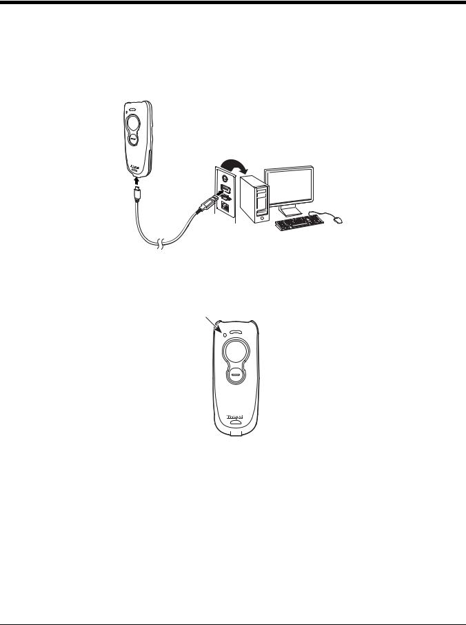
Charging with a PC
Charging your scanner battery through the USB port of a computer will take longer than charging with an electrical outlet. Connect the mini-USB connector to the scanner and the USB connector to the computer, as shown below.
Note: The mini-USB connector is only used for charging the scanner. If using a scanner in corded mode, it can also be used to configure the device via EZConfig (see page 8-3 for further information).
Battery Charge Indicator
When the battery is charging, the small LED at the top left of the scanner flashes orange. When the battery is fully charged, this LED is solid green. Refer to Scan LED Sequences and Meaning (page 3-6) and Low Battery Indicator (page
3-6) for the complete list of LED indications.
To use your scanner with a Honeywell Access Point (AP01-XXXBT), refer to Host ACK Responses, page 3-22 or Linking the Scanner to an Access Point, page 3-13.
1 - 2

Pairing the Scanner with Bluetooth® Devices
The scanner can be paired with Bluetooth devices such as personal computers, laptops, tablets, and Apple® devices.
1. Scan the appropriate Bluetooth Connect bar code below to establish one-way communication with the Voyager 1602g.
Bluetooth HID Keyboard
Connect
Bluetooth HID Japanese
Keyboard Connect
Note: If you want to use an Apple app or you are a developer creating an Apple app to communicate with the VG1602g, you would use SPP to establish two-way communication to control the scanner through that application. See Pairing the Scanner with an Apple Device Using SPP on page 1-4.
2.Set your personal computer, laptop, tablet, or Apple device so it searches for other Bluetooth devices. (Refer to your device’s User’s Guide for pairing instructions.)
3.Once your personal computer, laptop, tablet, or Apple device has located the scanner, select the scanner name. Some personal computers, laptops, or tablets will automatically pair with the scanner. If your device automatically pairs with the scanner, it displays a successful pairing message and you do not need to continue to the next step.
4.If your personal computer, laptop, or tablet does not automatically pair with the scanner, a PIN is displayed. This PIN must be scanned within 60 seconds. You must quickly scan Bluetooth PIN Code below, then scan the numeric bar code(s) for the PIN code from the chart below, then scan the Save bar code.
Bluetooth PIN Code
0
1
2
3
1 - 3

4
5
6
7
8
9
Save
Your personal computer, laptop, tablet, or Apple device should now be paired with the scanner.
Once the scanner battery is charged and you have paired it, you may begin scanning bar codes. Verify the scanner operation by scanning a bar code from the Sample Symbols in the back of this manual.
Pairing the Scanner with an Apple Device Using SPP
Serial port protocol, or SPP, is used to establish two-way Bluetooth communication with the scanner. If you want to use an Apple app or you are a developer creating an Apple app to communicate with the VG1602, use SPP to control the scanner through that application. This feature is only available with Apple's MFI-certified devices. Consult Apple to determine if your device is MFI-certified. Scan the bar code below to pair the Voyager 1602g with an Apple device using SPP.
Pair with Apple Device
Using SPP
Once the Apple device is connected to the Voyager 1602g using SPP, you must select the app that will be used to send commands to and receive responses from the scanner. To disconnect the association between the scanner and the app, use Bluetooth HID Keyboard Disconnect on page 3-1.
1 - 4
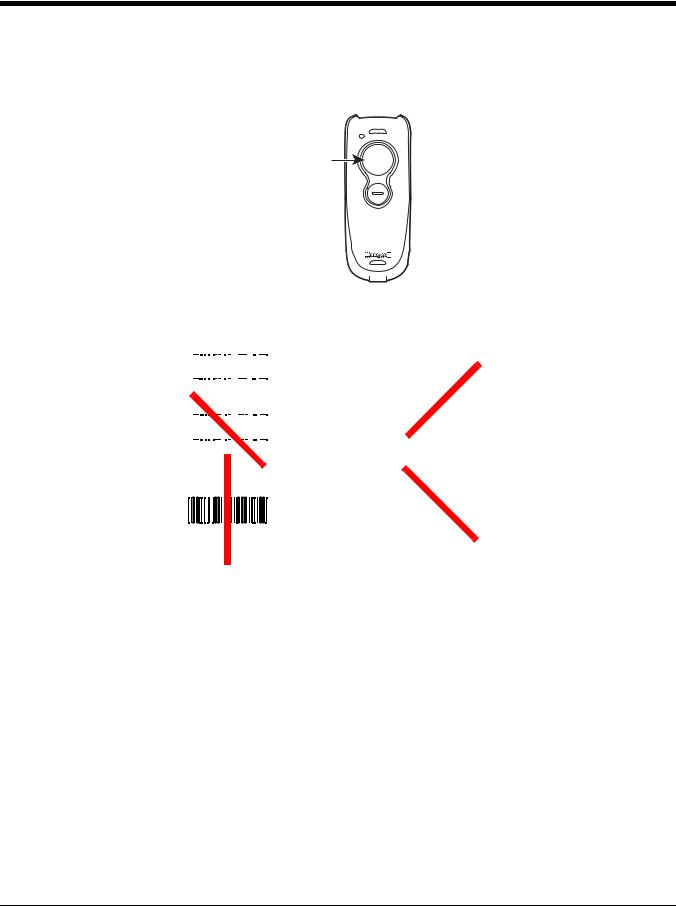
Reading Techniques
The Voyager 1602g has a large scan button just forward of a smaller, programmable button. (See Programmable Button on
page 4-1 for further information about the programmable button.)
Scan button
Press the scan button to project an aiming beam. This beam should be centered over the bar code, but it can be positioned in any direction for a good read.
Linear bar codes |
2D Matrix symbol |
|||||||||||||||||||
with aiming beam |
with aiming beam |
|||||||||||||||||||
|
|
|
|
|
|
|
|
|
|
|
|
|
|
|
|
|
|
|
|
|
|
|
|
|
|
|
|
|
|
|
|
|
|
|
|
|
|
|
|
|
|
|
|
|
|
|
|
|
|
|
|
|
|
|
|
|
|
|
|
|
|
|
|
|
|
|
|
|
|
|
|
|
|
|
|
|
|
|
|
|
|
|
|
|
|
|
|
|
|
|
|
|
|
|
|
|
|
|
|
|
|
|
|
|
|
|
|
|
|
|
|
|
|
|
|
|
|
|
|
|
|
|
|
|
|
The aiming beam is smaller when the scanner is closer to the code and larger when it is farther from the code. Symbologies with smaller bars or elements (mil size) should be read closer to the scanner. Symbologies with larger bars or elements (mil size) should be read farther from the scanner. To read single or multiple symbols (on a page or on an object), hold the scanner at an appropriate distance from the target, press the scan button, and center the aiming beam on the symbol. If the code being scanned is highly reflective (e.g., laminated), it may be necessary to tilt the code up 15° to 18° to prevent unwanted reflection.
Menu Bar Code Security Settings
Honeywell scanners are programmed by scanning menu bar codes or by sending serial commands to the scanner. If you want to restrict the ability to scan menu codes, you can use the Menu Bar Code Security settings. Contact the nearest technical support office (see Technical Assistance on page -ix) for further information.
1 - 5

Setting Custom Defaults
You have the ability to create a set of menu commands as your own, custom defaults. To do so, scan the Set Custom Defaults bar code below before scanning the menu commands for your custom defaults. If a menu command requires scanning numeric codes from the back cover, then a Save code, that entire sequence will be saved to your custom defaults. When you have entered all the commands you want to save for your custom defaults, scan the Save Custom Defaults bar code.
Set Custom Defaults
Save Custom Defaults
Note: The Custom Defaults settings apply to all workgroups Scanning the Save Defaults bar code also causes both the scanner and the host to perform a reset and become unlinked. You must relink (pair) the scanner to the host. See Wireless System Operation beginning on page 3-1 for additional information.
You may have a series of custom settings and want to correct a single setting. To do so, just scan the new setting to overwrite the old one. For example, if you had previously saved the setting for Beeper Volume at Low to your custom defaults, and decide you want the beeper volume set to High, just scan the Set Custom Defaults bar code, then scan the Beeper Volume High menu code, and then Save Custom Defaults. The rest of the custom defaults will remain, but the beeper volume setting will be updated.
Resetting the Custom Defaults
If you want the custom default settings restored to your scanner, scan the Activate Custom Defaults bar code below. This is the recommended default bar code for most users. It resets the scanner to the custom default settings. If there are no custom defaults, it will reset the scanner to the factory default settings. Any settings that have not been specified through the custom defaults will be defaulted to the factory default settings.
Activate Custom Defaults
Note: The Custom Defaults settings apply to all workgroups Scanning the Save Defaults bar code also causes both the scanner and the host to perform a reset and become unlinked. You must relink (pair) the scanner to the host. See Wireless System Operation beginning on page 3-1 for additional information.
1 - 6

2
Programming the Interface
Introduction
This chapter describes how to program your scanner for different keyboards and settings, and for an interface when using an Access Point (see Programming an Interface for an Access Point, beginning on page 2-12). The VG1602g is primarily designed as a cordless scanner. However, if you are using the VG1602g as a corded scanner, see Programming the VG1602 Corded Interface beginning on page 2-23.
Keyboard Country Layout
If your interface is USB Keyboard or Keyboard Wedge through an Access Point, or a Bluetooth Keyboard, your keyboard layout default is a US keyboard. To change this layout, refer to the chart below for your keyboard country. Scan the appropriate bar code below to change the layout.
By default, national character replacements are used for the following characters: #$@[\]^‘{|}~ See ISO 2022/ISO 646 Character Replacements on page A-7 to view the character replacements for each country.
Keyboard Countries
* United States
Albania
Azeri (Cyrillic)
Azeri (Latin)
Belarus
Belgium
Bosnia
Brazil
2 - 1

Keyboard Countries (Continued)
Brazil (MS)
Bulgaria (Cyrillic)
Bulgaria (Latin)
Canada (French legacy)
Canada (French)
Canada (Multilingual)
Croatia
Czech
Czech (Programmers)
Czech (QWERTY)
Czech (QWERTZ)
2 - 2
Keyboard Countries (Continued)
Denmark
Dutch (Netherlands)
Estonia
Faroese
Finland
France
Gaelic
Germany
Greek
Greek (220 Latin)
Greek (220)
2 - 3

Keyboard Countries (Continued)
Greek (319 Latin)
Greek (319)
Greek (Latin)
Greek (MS)
Greek (Polytonic)
Hebrew
Hungarian (101 key)
Hungary
Iceland
Irish
Italian (142)
2 - 4

Keyboard Countries (Continued)
Italy
Japan ASCII
Kazakh
Kyrgyz (Cyrillic)
Latin America
Latvia
Latvia (QWERTY)
Lithuania
Lithuania (IBM)
Macedonia
Malta
2 - 5

Keyboard Countries (Continued)
Mongolian (Cyrillic)
Norway
Poland
Polish (214)
Polish (Programmers)
Portugal
Romania
Russia
Russian (MS)
Russian (Typewriter)
SCS
2 - 6

Keyboard Countries (Continued)
Serbia (Cyrillic)
Serbia (Latin)
Slovakia
Slovakia (QWERTY)
Slovakia (QWERTZ)
Slovenia
Spain
Spanish variation
Sweden
Switzerland (French)
Switzerland (German)
2 - 7

Keyboard Countries (Continued)
Tatar
Turkey F
Turkey Q
Ukrainian
United Kingdom
United States (Dvorak)
United States (Dvorak left)
United Stated (Dvorak right)
United States (International)
Uzbek (Cyrillic)
Keyboard Style
This programs keyboard styles, such as Caps Lock and Shift Lock. If you have used Keyboard Conversion settings, they will override any of the following Keyboard Style settings. Default = Regular.
2 - 8

Regular is used when you normally have the Caps Lock key off.
* Regular
Caps Lock is used when you normally have the Caps Lock key on.
Caps Lock
Shift Lock is used when you normally have the Shift Lock key on (not common to U.S. keyboards).
Shift Lock
Automatic Caps Lock is used if you change the Caps Lock key on and off. The software tracks and reflects if you have Caps Lock on or off . This selection can only be used with systems that have an LED that notes the Caps Lock status (AT keyboards).
Automatic Caps Lock
Autocaps via NumLock bar code should be scanned in countries (e.g., Germany, France) where the Caps Lock key cannot be used to toggle Caps Lock. The NumLock option works similarly to the regular Autocaps, but uses the NumLock key to retrieve the current state of the Caps Lock.
Autocaps via NumLock
Emulate External Keyboard should be scanned if you do not have an external keyboard (IBM AT or equivalent).
Emulate External Keyboard
Note: After scanning the Emulate External Keyboard bar code, you must power cycle the host system.
Keyboard Conversion
Alphabetic keyboard characters can be forced to be all upper case or all lowercase. So if you have the following bar code: “abc569GK,” you can make the output “ABC569GK” by scanning Convert All Characters to Upper Case, or to “abc569gk” by scanning Convert All Characters to Lower Case.
These settings override Keyboard Style selections.
Note: If your interface is a keyboard wedge, first scan the menu code for Automatic Caps Lock (page 2-9). Otherwise, your output may not be as expected.
2 - 9

Default = Keyboard Conversion Off.
* Keyboard Conversion Off
Convert All Characters
to Upper Case
Convert All Characters
to Lower Case
Control Character Output
This selection sends a text string instead of a control character. For example, when the control character for a carriage return is expected, the output would display [CR] instead of the ASCII code of 0D. Refer to ASCII Conversion Chart (Code Page
1252) on page A-3. Only codes 00 through 1F are converted (the first column of the chart). Default = Off.
Note: Control + X (Control + ASCII) Mode overrides this mode.
Control Character Output On
* Control Character Output Off
Keyboard Modifiers
This modifies special keyboard features, such as CTRL+ ASCII codes and Turbo Mode.
Control + X (Control + ASCII) Mode On: The scanner sends key combinations for ASCII control characters for values 00-1F. Windows is the preferred mode. All keyboard country codes are supported. DOS mode is a legacy mode, and it does not support all keyboard country codes. New users should use the Windows mode. Refer to ASCII Conversion Chart (Code Page 1252), page A-3 for CTRL+ X Values.
Windows Mode Prefix/Suffix Off: The scanner sends key combinations for ASCII control characters for values 00-1F, but it does not translate prefix or suffix information.
Default = Control + X Mode Off.
Windows Mode Control + X
Mode On
2 - 10

* Control + X Mode Off
DOS Mode Control + X Mode On
Windows Mode Prefix/Suffix Off
Turbo Mode: The scanner sends characters to a terminal faster. If the terminal drops characters, do not use Turbo Mode.
Default = Off.
Turbo Mode On
* Turbo Mode Off
Numeric Keypad Mode: Sends numeric characters as if entered from a numeric keypad. Default = Off.
Numeric Keypad Mode On
* Numeric Keypad Mode Off
Automatic Direct Connect Mode: This selection can be used if you have an IBM AT style terminal and the system is dropping
characters. Default = Off.
Automatic Direct Connect Mode
On
* Automatic Direct Connect
Mode Off
2 - 11

Programming an Interface for an Access Point
If you are using a Honeywell Access Point (AP01-XXXBT) to communicate with the VG1602, you can use the following bar codes to program the Access Point interface. These bar codes set the Access Point for commonly used interfaces.
Keyboard Wedge
If you want your system programmed for an IBM PC AT and compatibles keyboard wedge interface with a USA keyboard, scan the bar code below, then power cycle the host. Keyboard wedge is the default interface. This interface is only appropriate for an Access Point.
Note: The following bar code also programs a carriage return (CR) suffix.
IBM PC AT and Compatibles with
CR suffix
Laptop Direct Connect
For most laptops, scanning the Laptop Direct Connect bar code allows operation of the scanner in parallel with the integral keyboard. The following Laptop Direct Connect bar code also programs a carriage return (CR) suffix and turns on Emulate External Keyboard (page 2-9). Power cycle the host after scanning this bar code. This interface is only appropriate for an Access Point.
Laptop Direct Connect
with CR suffix
RS232 Serial Port
The RS232 Interface bar code is used when connecting to the serial port of a PC or terminal. The following RS232 Interface bar code also programs a carriage return (CR) and a line feed (LF) suffix, baud rate, and data format as indicated below. It also changes the trigger mode to manual. This interface is only appropriate for an Access Point.
Option |
Setting |
|
|
Baud Rate |
115,200 bps |
Data Format |
8 data bits, no parity bit, 1 stop bit |
RS232 Interface
2 - 12
Loading...