


Voyager™ 1450g/1452g Series
Area-Imaging Scanner
User’s Guide

Disclaimer
Honeywell International Inc. (“HII”) reserves the right to make changes in specifications and other information contained in this document without prior notice, and the reader should in all cases consult HII to determine whether any such changes have been made. The information in this publication does not represent a commitment on the part of HII.
HII shall not be liable for technical or editorial errors or omissions contained herein; nor for incidental or consequential damages resulting from the furnishing, performance, or use of this material. HII disclaims all responsibility for the selection and use of software and/or hardware to achieve intended results.
This document contains proprietary information that is protected by copyright. All rights are reserved. No part of this document may be photocopied, reproduced, or translated into another language without the prior written consent of HII.
2014 Honeywell International Inc. All rights reserved.
Web Address: www.honeywellaidc.com
Microsoft® Windows® is a trademark or registered trademark of Microsoft Corporation.
Other product names or marks mentioned in this document may be trademarks or registered trademarks of other companies and are the property of their respective owners.
For patent information, please refer to www.hsmpats.com.

Table of Contents
Chapter 1 - Getting Started
About This Manual ............................................................................................................... |
1-1 |
Unpacking Your Device ....................................................................................................... |
1-1 |
Connecting the Device......................................................................................................... |
1-1 |
Connecting with USB ..................................................................................................... |
1-1 |
Connecting with Keyboard Wedge................................................................................. |
1-2 |
Connecting with RS232 Serial Port................................................................................ |
1-3 |
Connecting with RS485.................................................................................................. |
1-4 |
Mounting a CCB01-010BT Charge Base............................................................................. |
1-6 |
Reading Techniques ............................................................................................................ |
1-6 |
Menu Bar Code Security Settings........................................................................................ |
1-6 |
Setting Custom Defaults ...................................................................................................... |
1-7 |
Resetting the Custom Defaults ............................................................................................ |
1-7 |
Chapter 2 - Programming the Interface |
|
Introduction .......................................................................................................................... |
2-1 |
Programming the Interface - Plug and Play ......................................................................... |
2-1 |
Keyboard Wedge ................................................................................................................. |
2-1 |
Laptop Direct Connect ......................................................................................................... |
2-1 |
RS232 Serial Port ................................................................................................................ |
2-1 |
RS485 .................................................................................................................................. |
2-2 |
RS485 Packet Mode ...................................................................................................... |
2-2 |
USB IBM SurePos ............................................................................................................... |
2-3 |
USB PC or Macintosh Keyboard.......................................................................................... |
2-3 |
USB HID .............................................................................................................................. |
2-4 |
USB Serial ........................................................................................................................... |
2-4 |
CTS/RTS Emulation....................................................................................................... |
2-4 |
ACK/NAK Mode ............................................................................................................. |
2-4 |
Remote MasterMind™ for USB ........................................................................................... |
2-5 |
Verifone® Ruby Terminal Default Settings........................................................................... |
2-5 |
Gilbarco® Terminal Default Settings .................................................................................... |
2-5 |
Honeywell Bioptic Aux Port Configuration ........................................................................... |
2-6 |
Datalogic™ Magellan© Bioptic Aux Port Configuration........................................................ |
2-6 |
NCR Bioptic Aux Port Configuration .................................................................................... |
2-6 |
Wincor Nixdorf Terminal Default Settings ............................................................................ |
2-6 |
Wincor Nixdorf Beetle™ Terminal Default Settings ............................................................. |
2-7 |
Wincor Nixdorf RS232 Mode A ............................................................................................ |
2-7 |
Keyboard Country Layout .................................................................................................... |
2-8 |
Keyboard Style................................................................................................................... |
2-15 |
Keyboard Conversion ........................................................................................................ |
2-16 |
Control Character Output................................................................................................... |
2-17 |
Keyboard Modifiers ............................................................................................................ |
2-17 |
i

RS232 Modifiers ................................................................................................................ |
2-18 |
RS232 Baud Rate........................................................................................................ |
2-18 |
RS232 Word Length: Data Bits, Stop Bits, and Parity ................................................. |
2-19 |
RS232 Receiver Time-Out........................................................................................... |
2-20 |
RS232 Handshaking.................................................................................................... |
2-20 |
RS232 Timeout............................................................................................................ |
2-21 |
XON/XOFF .................................................................................................................. |
2-21 |
ACK/NAK ..................................................................................................................... |
2-22 |
Scanner to Bioptic Communication ................................................................................... |
2-22 |
Scanner-Bioptic Packet Mode ..................................................................................... |
2-22 |
Scanner-Bioptic ACK/NAK Mode................................................................................. |
2-22 |
Scanner-Bioptic ACK/NAK Timeout............................................................................. |
2-23 |
Chapter 3 - Cordless System Operation |
|
How the Cordless Charge Base/Access Point Works ......................................................... |
3-1 |
Linking the Scanner to a Charge Base................................................................................ |
3-1 |
Linking the Scanner to an Access Point .............................................................................. |
3-1 |
Replacing a Linked Scanner................................................................................................ |
3-2 |
Communication Between the Cordless System |
|
and the Host...................................................................................................................... |
3-2 |
Programming the Scanner and Base or Access Point ........................................................ |
3-3 |
RF (Radio Frequency) Module Operation ........................................................................... |
3-3 |
System Conditions............................................................................................................... |
3-3 |
Linking Process ............................................................................................................. |
3-3 |
Scanner Is Out of Range ............................................................................................... |
3-3 |
Scanner Is Moved Back Into Range .............................................................................. |
3-3 |
Out of Range and Back into Range with Batch Mode On.............................................. |
3-3 |
Page Button......................................................................................................................... |
3-3 |
About the Battery................................................................................................................. |
3-4 |
Charging Information ..................................................................................................... |
3-4 |
Battery Recommendations ............................................................................................ |
3-4 |
Proper Disposal of the Battery....................................................................................... |
3-4 |
Beeper and LED Sequences and Meaning ......................................................................... |
3-5 |
Scanner LED Sequences and Meaning......................................................................... |
3-5 |
Base/Access Point LED Sequences and Meaning ........................................................ |
3-5 |
Base Power Communication Indicator........................................................................... |
3-5 |
Reset Scanner..................................................................................................................... |
3-6 |
Scanning While in Base Cradle ........................................................................................... |
3-6 |
Base Charging Modes ......................................................................................................... |
3-6 |
Paging ................................................................................................................................. |
3-7 |
Paging Mode.................................................................................................................. |
3-7 |
Paging Pitch................................................................................................................... |
3-7 |
Error Indicators .................................................................................................................... |
3-8 |
Beeper Pitch - Base Error.............................................................................................. |
3-8 |
Number of Beeps - Base Error ...................................................................................... |
3-8 |
Scanner Report ................................................................................................................... |
3-8 |
Scanner Address ................................................................................................................. |
3-9 |
Base or Access Point Address ............................................................................................ |
3-9 |
ii

Scanner Modes ................................................................................................................... |
3-9 |
Charge Only Mode......................................................................................................... |
3-9 |
Linked Modes ................................................................................................................ |
3-9 |
Unlinking the Scanner ....................................................................................................... |
3-10 |
Override Locked Scanner ............................................................................................ |
3-10 |
Out-of-Range Alarm .......................................................................................................... |
3-10 |
Alarm Sound Type ....................................................................................................... |
3-11 |
Scanner Power Time-Out Timer........................................................................................ |
3-11 |
Flexible Power Management ............................................................................................. |
3-12 |
Batch Mode ....................................................................................................................... |
3-13 |
Batch Mode Beep ........................................................................................................ |
3-14 |
Batch Mode Storage .................................................................................................... |
3-14 |
Batch Mode Quantity ................................................................................................... |
3-15 |
Batch Mode Output Order............................................................................................ |
3-16 |
Total Records .............................................................................................................. |
3-17 |
Delete Last Code ......................................................................................................... |
3-17 |
Clear All Codes............................................................................................................ |
3-17 |
Transmit Records to Host ............................................................................................ |
3-17 |
Batch Mode Transmit Delay ........................................................................................ |
3-17 |
Multiple Scanner Operation ............................................................................................... |
3-18 |
Scanner Name................................................................................................................... |
3-18 |
Application Work Groups................................................................................................... |
3-19 |
Application Work Group Selection ............................................................................... |
3-20 |
Resetting the Factory Defaults: All Application Work Groups ........................................... |
3-20 |
Resetting the Custom Defaults: All Application Work Groups ........................................... |
3-21 |
Using the Scanner with Bluetooth Devices........................................................................ |
3-21 |
Bluetooth HID Keyboard Connect................................................................................ |
3-21 |
Virtual Keyboard .......................................................................................................... |
3-22 |
Bluetooth HID Keyboard Disconnect ........................................................................... |
3-23 |
Bluetooth Serial Port - PCs/Laptops ............................................................................ |
3-23 |
PDAs/Mobility Systems Devices.................................................................................. |
3-23 |
Changing the Scanner’s Bluetooth PIN Code.............................................................. |
3-23 |
Minimizing Bluetooth/ISM Band Network Activity .............................................................. |
3-23 |
Auto Reconnect Mode ................................................................................................. |
3-24 |
Maximum Link Attempts .............................................................................................. |
3-24 |
Relink Time-Out........................................................................................................... |
3-25 |
Bluetooth/ISM Network Activity Examples................................................................... |
3-25 |
Host Acknowledgment....................................................................................................... |
3-26 |
Chapter 4 - Input/Output Settings |
|
Power Up Beeper ................................................................................................................ |
4-1 |
Beep on BEL Character....................................................................................................... |
4-1 |
Trigger Click ........................................................................................................................ |
4-1 |
iii

Good Read and Error Indicators.......................................................................................... |
4-2 |
Beeper – Good Read..................................................................................................... |
4-2 |
Beeper Volume – Good Read........................................................................................ |
4-2 |
Beeper Pitch – Good Read............................................................................................ |
4-2 |
Beeper Pitch – Error ...................................................................................................... |
4-3 |
Beeper Duration – Good Read ...................................................................................... |
4-3 |
LED – Good Read ......................................................................................................... |
4-3 |
Number of Beeps – Good Read .................................................................................... |
4-4 |
Number of Beeps – Error............................................................................................... |
4-4 |
Good Read Delay .......................................................................................................... |
4-4 |
User-Specified Good Read Delay.................................................................................. |
4-4 |
Manual Trigger Mode .......................................................................................................... |
4-5 |
LED Illumination - Manual Trigger ................................................................................. |
4-5 |
Serial Trigger Mode ............................................................................................................. |
4-5 |
Read Time-Out .............................................................................................................. |
4-5 |
Presentation Mode .............................................................................................................. |
4-6 |
Idle Illumination - Presentation Mode ............................................................................ |
4-6 |
Presentation Sensitivity ................................................................................................. |
4-6 |
Presentation Centering .................................................................................................. |
4-6 |
In-Stand Sensor Mode......................................................................................................... |
4-8 |
Poor Quality Codes ............................................................................................................. |
4-8 |
Poor Quality 1D Codes .................................................................................................. |
4-8 |
Poor Quality PDF Codes ............................................................................................... |
4-9 |
CodeGate® .......................................................................................................................... |
4-9 |
Mobile Phone Read Mode ................................................................................................... |
4-9 |
Hands Free Time-Out.......................................................................................................... |
4-9 |
Reread Delay..................................................................................................................... |
4-10 |
User-Specified Reread Delay ............................................................................................ |
4-10 |
2D Reread Delay ......................................................................................................... |
4-10 |
Character Activation Mode ................................................................................................ |
4-11 |
Activation Character .................................................................................................... |
4-11 |
End Character Activation After Good Read ................................................................. |
4-12 |
Character Activation Laser Timeout ............................................................................ |
4-12 |
Character Deactivation Mode ............................................................................................ |
4-12 |
Deactivation Character ................................................................................................ |
4-12 |
Illumination Lights.............................................................................................................. |
4-13 |
Aimer Delay ....................................................................................................................... |
4-13 |
User-Specified Aimer Delay......................................................................................... |
4-13 |
Aimer Mode ....................................................................................................................... |
4-13 |
Centering ........................................................................................................................... |
4-14 |
No Read ............................................................................................................................ |
4-15 |
Video Reverse ................................................................................................................... |
4-16 |
Working Orientation........................................................................................................... |
4-16 |
iv

Chapter 5 - Data Editing
Prefix/Suffix Overview ......................................................................................................... |
5-1 |
To Add a Prefix or Suffix:............................................................................................... |
5-1 |
To Clear One or All Prefixes or Suffixes ........................................................................ |
5-2 |
To Add a Carriage Return Suffix to All Symbologies ..................................................... |
5-2 |
Prefix Selections.................................................................................................................. |
5-2 |
Suffix Selections .................................................................................................................. |
5-2 |
Function Code Transmit ...................................................................................................... |
5-3 |
Intercharacter, Interfunction, and Intermessage Delays...................................................... |
5-3 |
Intercharacter Delay ...................................................................................................... |
5-3 |
User Specified Intercharacter Delay .............................................................................. |
5-3 |
Interfunction Delay......................................................................................................... |
5-4 |
Intermessage Delay....................................................................................................... |
5-4 |
Chapter 6 - Data Formatting |
|
Data Format Editor Introduction .......................................................................................... |
6-1 |
Add a Data Format .............................................................................................................. |
6-1 |
Other Programming Selections...................................................................................... |
6-2 |
Terminal ID Table ................................................................................................................ |
6-3 |
Data Format Editor Commands........................................................................................... |
6-3 |
Move Commands........................................................................................................... |
6-4 |
Search Commands ........................................................................................................ |
6-5 |
Miscellaneous Commands............................................................................................. |
6-7 |
Data Formatter .................................................................................................................... |
6-9 |
Primary/Alternate Data Formats .......................................................................................... |
6-9 |
Chapter 7 - Symbologies |
|
All Symbologies ................................................................................................................... |
7-1 |
Message Length Description ............................................................................................... |
7-1 |
Codabar............................................................................................................................... |
7-2 |
Codabar Concatenation................................................................................................. |
7-3 |
Code 39 ............................................................................................................................... |
7-4 |
Code 32 Pharmaceutical (PARAF) ................................................................................ |
7-5 |
Full ASCII....................................................................................................................... |
7-6 |
Code 39 Code Page ...................................................................................................... |
7-6 |
Interleaved 2 of 5................................................................................................................. |
7-7 |
NEC 2 of 5 ........................................................................................................................... |
7-8 |
Code 93 ............................................................................................................................... |
7-9 |
Code 93 Code Page .................................................................................................... |
7-10 |
Straight 2 of 5 Industrial (three-bar start/stop)................................................................... |
7-11 |
Straight 2 of 5 IATA (two-bar start/stop) ............................................................................ |
7-12 |
Matrix 2 of 5....................................................................................................................... |
7-13 |
Code 11 ............................................................................................................................. |
7-14 |
Code 128 ........................................................................................................................... |
7-15 |
ISBT 128 Concatenation.............................................................................................. |
7-15 |
Code 128 Code Page .................................................................................................. |
7-16 |
v

GS1-128 ............................................................................................................................ |
7-17 |
UPC-A ............................................................................................................................... |
7-17 |
UPC-A/EAN-13 with Extended Coupon Code ................................................................... |
7-19 |
Coupon GS1 DataBar Output............................................................................................ |
7-20 |
UPC-E0 ............................................................................................................................. |
7-20 |
UPC-E1 ............................................................................................................................. |
7-22 |
EAN/JAN-13 ...................................................................................................................... |
7-23 |
Convert UPC-A to EAN-13 .......................................................................................... |
7-23 |
ISBN Translate ............................................................................................................ |
7-25 |
EAN/JAN-8 ........................................................................................................................ |
7-25 |
MSI .................................................................................................................................... |
7-27 |
GS1 DataBar Omnidirectional ........................................................................................... |
7-29 |
GS1 DataBar Limited......................................................................................................... |
7-29 |
GS1 DataBar Expanded .................................................................................................... |
7-30 |
Codablock A ...................................................................................................................... |
7-30 |
Codablock F ...................................................................................................................... |
7-31 |
PDF417 ............................................................................................................................. |
7-32 |
MacroPDF417 ................................................................................................................... |
7-32 |
MicroPDF417..................................................................................................................... |
7-33 |
GS1 Composite Codes...................................................................................................... |
7-33 |
UPC/EAN Version........................................................................................................ |
7-34 |
GS1 Emulation .................................................................................................................. |
7-34 |
TCIF Linked Code 39 (TLC39) .......................................................................................... |
7-35 |
QR Code............................................................................................................................ |
7-35 |
QR Code Page ............................................................................................................ |
7-36 |
Data Matrix ........................................................................................................................ |
7-37 |
Data Matrix Code Page ............................................................................................... |
7-37 |
MaxiCode .......................................................................................................................... |
7-38 |
Aztec Code ........................................................................................................................ |
7-39 |
Aztec Code Page......................................................................................................... |
7-39 |
Chinese Sensible (Han Xin) Code..................................................................................... |
7-40 |
Postal Codes - 2D ............................................................................................................. |
7-41 |
Single 2D Postal Codes:.............................................................................................. |
7-41 |
Combination 2D Postal Codes:.................................................................................... |
7-42 |
Postal Codes - Linear ........................................................................................................ |
7-45 |
China Post (Hong Kong 2 of 5).................................................................................... |
7-45 |
Korea Post ................................................................................................................... |
7-46 |
Chapter 8 - Interface Keys |
|
Keyboard Function Relationships........................................................................................ |
8-1 |
Supported Interface Keys .................................................................................................... |
8-2 |
Chapter 9 - Utilities |
|
To Add a Test Code I.D. Prefix to All Symbologies ............................................................. |
9-1 |
Show Decoder Revision ...................................................................................................... |
9-1 |
Show Scan Driver Revision ................................................................................................. |
9-1 |
Show Software Revision...................................................................................................... |
9-1 |
vi

Show Data Format............................................................................................................... |
9-1 |
Test Menu............................................................................................................................ |
9-2 |
EZConfig-Scanning Introduction.......................................................................................... |
9-2 |
Installing EZConfig-Scanning from the Web.................................................................. |
9-2 |
Resetting the Factory Defaults ............................................................................................ |
9-3 |
Chapter 10 - Serial Programming Commands |
|
Conventions....................................................................................................................... |
10-1 |
Menu Command Syntax .................................................................................................... |
10-1 |
Query Commands ............................................................................................................. |
10-1 |
Responses................................................................................................................... |
10-2 |
Trigger Commands............................................................................................................ |
10-3 |
Resetting the Custom Defaults.......................................................................................... |
10-3 |
Menu Commands .............................................................................................................. |
10-3 |
Chapter 11 - Product Specifications |
|
Voyager 1450g Scanner Product Specifications ............................................................... |
11-1 |
Voyager 1452g Cordless Scanner Product Specifications ................................................ |
11-2 |
CCB01-010BT Charge Base Product Specifications......................................................... |
11-3 |
Standard Cable Pinouts..................................................................................................... |
11-4 |
Serial Output................................................................................................................ |
11-4 |
USB ............................................................................................................................. |
11-4 |
RS485 Output .............................................................................................................. |
11-5 |
Chapter 12 - Maintenance |
|
Repairs .............................................................................................................................. |
12-1 |
Maintenance ...................................................................................................................... |
12-1 |
Cleaning the Device..................................................................................................... |
12-1 |
Inspecting Cords and Connectors ............................................................................... |
12-1 |
Replacing Cables in Corded Scanners.............................................................................. |
12-1 |
Replacing a Corded Scanner Interface Cable ............................................................. |
12-2 |
Replacing Cables and Batteries in Cordless Systems ...................................................... |
12-2 |
Replacing an Interface Cable in a Base ...................................................................... |
12-2 |
Changing a Cordless Scanner Battery ........................................................................ |
12-3 |
Troubleshooting a Corded Scanner................................................................................... |
12-3 |
Troubleshooting a Cordless System.................................................................................. |
12-3 |
Troubleshooting a Base............................................................................................... |
12-3 |
Troubleshooting a Cordless Scanner .......................................................................... |
12-4 |
Chapter 13 - Customer Support |
|
Technical Assistance......................................................................................................... |
13-1 |
vii

Appendix A - Reference Charts
Symbology Charts ............................................................................................................... |
A-1 |
Linear Symbologies ....................................................................................................... |
A-1 |
2D Symbologies............................................................................................................. |
A-2 |
Postal Symbologies ....................................................................................................... |
A-2 |
ASCII Conversion Chart (Code Page 1252)........................................................................ |
A-3 |
Lower ASCII Reference Table............................................................................................. |
A-4 |
ISO 2022/ISO 646 Character Replacements ...................................................................... |
A-7 |
Unicode Key Maps .............................................................................................................. |
A-9 |
Sample Symbols
Programming Chart
viii
1
Getting Started
About This Manual
This User’s Guide provides installation and programming instructions for the Voyager™ 1450g corded area-imaging scanners and Voyager 1452g cordless area-imaging scanners. Product specifications, dimensions, warranty, and customer support information are also included.
Note: The selections in this User’s Guide are dependent on the Voyager 145Xg model you have purchased.
PDF and 2 dimensional bar codes can only be read by model 145Xg2D and cannot be read by model 145Xg1D.
Honeywell bar code scanners are factory programmed for the most common terminal and communications settings. If you need to change these settings, programming is accomplished by scanning the bar codes in this guide.
An asterisk (*) next to an option indicates the default setting.
Unpacking Your Device
After you open the shipping carton containing the product, take the following steps:
•Check for damage during shipment. Report damage immediately to the carrier who delivered the carton.
•Make sure the items in the carton match your order.
•Save the shipping container for later storage or shipping.
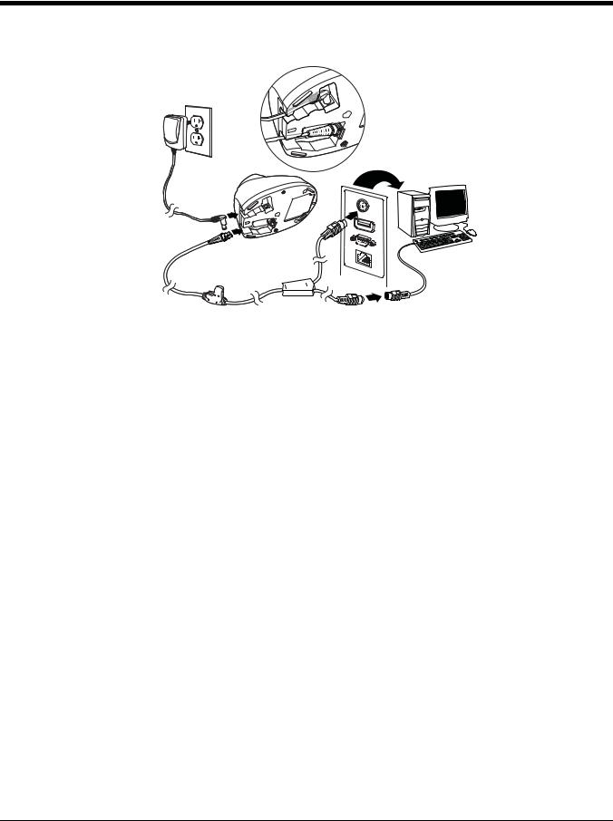
Connecting the Device
Connecting with USB
A scanner or a cordless base can be connected to the USB port of a computer.
1. Connect the appropriate interface cable to the device first, then to the computer.
Corded Voyager 1450g
USB Connection:
1 - 1

CCB01-010BTBase
USB Connection:
Note: The power supply must be ordered separately, if needed.
2.If you are connecting a CCB01-010BT Base, make sure the cables are secured in the wireways in the bottom of the cordless base and the base sits flat on a horizontal surface.
3.The scanner beeps.
4.Verify the scanner or cordless base operation by scanning a bar code from the Sample Symbols in the back of this manual.
The unit defaults to a USB PC Keyboard. Refer to page 2-3 for other USB terminal settings.
For additional USB programming and technical information, refer to “USB Application Note,” available at www.honeywellaidc.com.
Connecting with Keyboard Wedge
A scanner or cordless base can be connected between the keyboard and PC as a “keyboard wedge,” where the scanner provides data output that is similar to keyboard entries. The following is an example of a keyboard wedge connection:
1.Turn off power and disconnect the keyboard cable from the back of the terminal/computer.
2.Connect the appropriate interface cable to the device and to the terminal/computer.
Corded Voyager 1450g
Keyboard Wedge Connection:
1 - 2
CCB01-010BT Base
Keyboard Wedge Connection:
Note: The power supply must be ordered separately, if needed.
3.If you are connecting a CCB01-010BT Base, make sure the cables are secured in the wireways in the bottom of the cordless base and the base sits flat on a horizontal surface.
4.Turn the terminal/computer power back on. The scanner beeps.
5.Verify the scanner or cordless base operation by scanning a bar code from the Sample Symbols in the back of this manual. The scanner beeps once.
The unit defaults to an IBM PC AT and compatibles keyboard wedge interface with a USA keyboard. A carriage return (CR) suffix is added to bar code data.
Connecting with RS232 Serial Port
1.Turn off power to the terminal/computer.
2.Connect the appropriate interface cable to the device.
Note: For the scanner or cordless base to work properly, you must have the correct cable for your type of terminal/computer.
1 - 3

Corded Voyager 1450g
RS232 Serial Port Connection:
CCB01-010BT Base
RS232 Serial Port Connection:
Note: The power supply must be ordered separately, if needed.
3.If you are connecting a CCB01-010BT Base, make sure the cables are secured in the wireways in the bottom of the cordless base and the base sits flat on a horizontal surface.
4.Plug the serial connector into the serial port on your computer. Tighten the two screws to secure the connector to the port.
5.Once the scanner or cordless base has been fully connected, power up the computer.
This interface programs 115,200 baud, 8 data bits, no parity, and 1 stop bit.
Connecting with RS485
A scanner or cordless base can be connected for an IBM POS terminal interface. 1. Connect the appropriate interface cable to the device, then to the computer.
1 - 4

Corded Voyager 1450g
RS232 Serial Port Connection:
CCB01-010BT Base
RS485 Connection:
2.Turn the terminal/computer power back on. The scanner beeps.
3.Verify the scanner or cordless base operation by scanning a bar code from the Sample Symbols in the back of this manual. The scanner beeps once.
For further RS485 settings, refer to RS485, page 2-2.
1 - 5
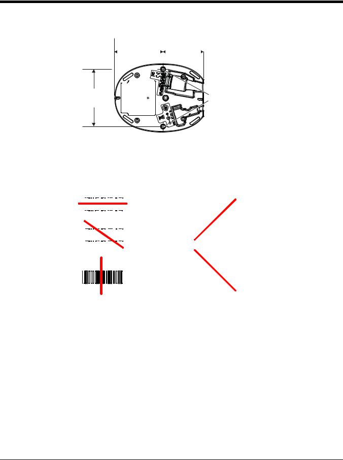
Mounting a CCB01-010BT Charge Base
|
|
|
2.8 in. |
|
|
|
|
|
2.36 in. |
|
|
|
|
|
|
|
|
|
|
|
|||
|
|
|
72.1mm |
|
|
|
|
59.84mm |
|||
|
|
|
|
|
|
|
|
|
|
|
|
|
|
|
|
|
|
|
|
|
|
|
|
|
|
|
|
|
|
|
|
|
|
|
|
3.35 in. |
8x32 thread |
|
85.09mm |
||
x .39 in. (10mm) deep |
||
|
Reading Techniques
The scanner has a view finder that projects a bright red aiming beam that corresponds to the scanner’s horizontal field of view. The aiming beam should be centered over the bar code, but it can be positioned in any direction for a good read.
Linear bar code |
2D Matrix symbol |
|||||||||||||||||||||
|
|
|
|
|
|
|
|
|
|
|
|
|
|
|
|
|
|
|
|
|
|
|
|
|
|
|
|
|
|
|
|
|
|
|
|
|
|
|
|
|
|
|
|
|
|
|
|
|
|
|
|
|
|
|
|
|
|
|
|
|
|
|
|
|
|
|
|
|
|
|
|
|
|
|
|
|
|
|
|
|
|
|
|
|
|
|
|
|
|
|
|
|
|
|
|
|
|
|
|
|
|
|
|
|
|
|
|
|
|
|
|
|
|
|
|
|
|
|
|
|
|
|
|
|
|
|
|
|
|
|
|
|
|
|
|
|
|
The aiming beam or pattern is smaller when the scanner is closer to the code and larger when it is farther from the code. Symbologies with smaller bars or elements (mil size) should be read closer to the unit. Symbologies with larger bars or elements (mil size) should be read farther from the unit. To read single or multiple symbols (on a page or on an object), hold the scanner at an appropriate distance from the target, press the trigger, and center the aiming beam or pattern on the symbol. If the code being scanned is highly reflective (e.g., laminated), it may be necessary to tilt the code up 15° to 18° to prevent unwanted reflection.
Menu Bar Code Security Settings
Honeywell scanners are programmed by scanning menu bar codes or by sending serial commands to the scanner. If you want to restrict the ability to scan menu codes, you can use the Menu Bar Code Security settings. Please contact the nearest technical support office (see Customer Support on page 13-1) for further information.
1 - 6

Setting Custom Defaults
You have the ability to create a set of menu commands as your own, custom defaults. To do so, scan the Set Custom Defaults bar code below before scanning the menu commands for your custom defaults. If a menu command requires scanning numeric codes from the back cover, then a Save code, that entire sequence will be saved to your custom defaults. When you have entered all the commands you want to save for your custom defaults, scan the Save Custom Defaults bar code.
Set Custom Defaults
Save Custom Defaults
Note: When using a cordless system, the Custom Defaults settings apply to all workgroups. Scanning the Save Defaults bar code also causes both the scanner and the base or Access Point to perform a reset and become unlinked. The scanner must be placed in its base to re-establish the link before any setup codes are entered. If using an Access Point, the linking bar code must be scanned. See Cordless System Operation beginning on page 3-1 for additional information.
You may have a series of custom settings and want to correct a single setting. To do so, just scan the new setting to overwrite the old one. For example, if you had previously saved the setting for Beeper Volume at Low to your custom defaults, and decide you want the beeper volume set to High, just scan the Set Custom Defaults bar code, then scan the Beeper Volume High menu code, and then Save Custom Defaults. The rest of the custom defaults will remain, but the beeper volume setting will be updated.
Resetting the Custom Defaults
If you want the custom default settings restored to your scanner, scan the Activate Custom Defaults bar code below. This is the recommended default bar code for most users. It resets the scanner to the custom default settings. If there are no custom defaults, it will reset the scanner to the factory default settings. Any settings that have not been specified through the custom defaults will be defaulted to the factory default settings.
Activate Custom Defaults
Note: If using a cordless system, scanning this bar code also causes both the scanner and the base or Access Point to perform a reset and become unlinked. The scanner must be placed in its base to re-establish the link. If using an Access Point, the linking bar code must be scanned. See Cordless System Operation beginning on page 3-1 for additional information.
1 - 7

1 - 8

2
Programming the Interface
Introduction
This chapter describes how to program your system for the desired interface.
Programming the Interface - Plug and Play
Plug and Play bar codes provide instant scanner set up for commonly used interfaces.
Note: After you scan one of the codes, power cycle the host terminal to have the interface in effect.
Keyboard Wedge
If you want your system programmed for an IBM PC AT and compatibles keyboard wedge interface with a USA keyboard, scan the bar code below. Keyboard wedge is the default interface.
Note: The following bar code also programs a carriage return (CR) suffix.
IBM PC AT and Compatibles with
CR suffix
Laptop Direct Connect
For most laptops, scanning the Laptop Direct Connect bar code allows operation of the scanner in parallel with the integral keyboard. The following Laptop Direct Connect bar code also programs a carriage return (CR) suffix and turns on Emulate External Keyboard (page 2-16).
Laptop Direct Connect
with CR suffix
RS232 Serial Port
The RS232 Interface bar code is used when connecting to the serial port of a PC or terminal. The following RS232 Interface bar code also programs a carriage return (CR) and a line feed (LF) suffix, baud rate, and data format as indicated below. It also changes the trigger mode to manual.
Option |
Setting |
Baud Rate |
115,200 bps |
Data Format |
8 data bits, no parity bit, 1 stop bit |
RS232 Interface
2 - 1

RS485
Scan one of the following “Plug and Play” codes to program the scanner for an IBM POS terminal interface.
Note: After scanning one of these codes, you must power cycle the cash register.
IBM Port 5B Interface
IBM Port 9B
HHBCR-1 Interface
IBM Port 17 Interface
IBM Port 9B
HHBCR-2 Interface
Each bar code above also programs the following suffixes for each symbology:
Symbology |
Suffix |
Symbology |
Suffix |
||
EAN 8 |
0C |
Code 39 |
|
00 |
0A 0B |
EAN 13 |
16 |
Interleaved 2 of 5 |
00 |
0D 0B |
|
UPC A |
0D |
Code 128 |
* |
00 |
0A 0B |
UPC E |
0A |
Code 128 |
** |
00 |
18 0B |
|
|
MaxiCode |
|
00 |
2F 0B |
* Suffixes programmed for Code 128 with IBM 4683 Port 5B, IBM 4683 Port 9B HHBCR-1, and IBM 4683 Port 17 Interfaces **Suffixes programmed for Code 128 with IBM 4683 Port 9 HHBCR-2 Interface
RS485 Packet Mode
The following selection allows you to break up large bar code data into smaller packets on an IBM POS terminal. To break up large bar codes into small packets, scan the Packet Mode On bar code below. Scan the Packet Mode Off bar code if you
want large bar code data to be sent to the host in a single chunk. Default = Packet Mode Off.
* Packet Mode Off
Packet Mode On
2 - 2
RS485 Packet Length
If you are using Packet mode, you can specify the size of the data “packet” that is sent to the host. Scan the Packet Length bar code, then then the packet size (from 20 - 256) from the Programming Chart inside the back cover of this manual, then Save. Default = 40.
Packet Length
USB IBM SurePos
Scan one of the following “Plug and Play” codes to program the scanner for an IBM SurePos (USB handheld scanner) or IBM SurePos (USB tabletop scanner) interface.
Note: After scanning one of these codes, you must power cycle the cash register.
USB IBM SurePos
(USB Handheld Scanner)
Interface
USB IBM SurePos
(USB Tabletop Scanner)
Interface
Each bar code above also programs the following suffixes for each symbology:
Symbology |
Suffix |
Symbology |
Suffix |
|
|
EAN 8 |
0C |
Code 39 |
00 |
0A |
0B |
EAN 13 |
16 |
Interleaved 2 of 5 |
00 |
0D 0B |
|
UPC A |
0D |
Code 128 |
00 |
18 |
0B |
UPC E |
0A |
Code 39 |
00 |
0A |
0B |
USB PC or Macintosh Keyboard
Scan one of the following codes to program the scanner for USB PC Keyboard or USB Macintosh Keyboard. Scanning these
codes also adds a CR and LF.
USB Keyboard (PC)
USB Keyboard (Mac)
USB Japanese Keyboard (PC)
2 - 3

USB HID
Scan the following code to program the scanner for USB HID bar code scanners.
USB HID Bar Code Scanner
USB Serial
Scan the following code to program the scanner to emulate a regular RS232-based COM Port. If you are using a Microsoft® Windows® PC, you will need to download a driver from the Honeywell website (www.honeywellaidc.com). The driver will use the next available COM Port number. Apple® Macintosh computers recognize the scanner as a USB CDC class device and automatically uses a class driver.
USB Serial
Note: No extra configuration (e.g., baud rate) is necessary.
CTS/RTS Emulation
CTS/RTS Emulation On
* CTS/RTS Emulation Off
ACK/NAK Mode
ACK/NAK Mode On
* ACK/NAK Mode Off
2 - 4

Remote MasterMind™ for USB
When using a USB interface, you may wish to configure your scanner to communicate with Remote MasterMind Scanner Management Software (ReM). Scan the ReM On bar code to communicate with ReM. To disable this capability, scan ReM Off.
Default = ReM On.
Note: Remote MasterMind settings apply only to the Voyager 1450g. They are not supported by the Voyager 1452g.
ReM Off
* ReM On
Verifone® Ruby Terminal Default Settings
Scan the following Plug and Play code to program the scanner for a Verifone Ruby terminal. This bar code sets the baud rate to 1200 bps and the data format to 8 data bits, mark parity bit, 1 stop bit. It also adds a line feed (LF) suffix and programs the following prefixes for each symbology:
Symbology |
Prefix |
|
|
UPC-A |
A |
UPC-E |
A |
EAN-8 |
FF |
EAN-13 |
F |
Verifone Ruby Settings
Gilbarco® Terminal Default Settings
Scan the following Plug and Play code to program the scanner for a Gilbarco terminal. This bar code sets the baud rate to 2400 bps and the data format to 7 data bits, even parity, 2 stop bits. It also also adds a carriage return (CR) suffix and programs the following prefixes for each symbology:
Symbology |
Prefix |
|
|
UPC-A |
A |
UPC-E |
E0 |
EAN-8 |
FF |
EAN-13 |
F |
Gilbarco Settings
2 - 5

Honeywell Bioptic Aux Port Configuration
Scan the following Plug and Play code to program the scanner for a Honeywell bioptic scanner auxiliary port configuration. This bar code sets the baud rate to 38400 bps and the data format to 8 data bits, no parity, 1 stop bit.
Honeywell Bioptic Settings
Datalogic™ Magellan© Bioptic Aux Port Configuration
Scan the following Plug and Play code to program the scanner for a Datalogic Magellan bioptic scanner auxiliary port configuration. This bar code sets the baud rate to 9600 bps and the data format to 8 data bits, no parity, 1 stop bit.
Datalogic Magellan Bioptic Settings
NCR Bioptic Aux Port Configuration
Scan the following Plug and Play code to program the scanner for an NCR bioptic scanner auxiliary port configuration. The following prefixes are programmed for each symbology:
Symbology |
Prefix |
Symbology |
Prefix |
UPC-A |
A |
Interleaved 2 of 5 |
b |
UPC-E |
E0 |
Code 128 |
f |
|
|
GS1 DataBar |
r |
|
|
Omnidirecitonal |
|
EAN-8 |
FF |
GS1 DataBar |
r |
|
|
Expanded |
|
EAN-13 |
F |
Codabar |
N |
Code 39 |
a |
Code 32 |
a |
|
|
Pharmaceutical |
|
|
|
(PARAF) |
|
NCR Bioptic Settings
Wincor Nixdorf Terminal Default Settings
Scan the following Plug and Play code to program the scanner for a Wincor Nixdorf terminal. This bar code sets the baud rate to 9600 bps and the data format to 8 data bits, no parity, 1 stop bit.
Wincor Nixdorf Terminal Settings
2 - 6

Wincor Nixdorf Beetle™ Terminal Default Settings
Scan the following Plug and Play code to program the scanner for a Wincor Nixdorf Beetle terminal. This bar code sets the baud rate to 115200 bps and the data format to 8 data bits, no parity, 1 stop bit. The following prefixes are programmed for each symbology:
Symbology |
Prefix |
Symbology |
Prefix |
Aztec Code |
V |
Interleaved 2 of 5 |
I |
Codabar |
N |
MaxiCode |
T |
Code 93 |
L |
MicroPDF417 |
S |
Code 128 |
K |
PDF417 |
Q |
Data Matrix |
R |
QR Code |
U |
EAN-8 |
B |
Straight 2 of 5 IATA |
H |
EAN-13 |
A |
UPC-A |
A0 |
GS1 DataBar |
E |
UPC-E |
C |
GS1-128 |
P |
All other bar codes |
M |
Wincor Nixdorf Beetle Settings
Wincor Nixdorf RS232 Mode A
Scan the following Plug and Play code to program the scanner for a Wincor Nixdorf RS232 Mode A terminal. This bar code sets the baud rate to 9600 bps and the data format to 8 data bits, odd parity, 1 stop bit. The following prefixes are programmed for each symbology:
Symbology |
Prefix |
Symbology |
Prefix |
Code 128 |
K |
EAN-13 |
A |
Code 93 |
L |
GS1-128 |
K |
Codabar |
N |
Interleaved 2 of 5 |
I |
UPC-A |
A0 |
Plessey |
O |
UPC-E |
C |
Straight 2 of 5 IATA |
H |
EAN-8 |
B |
GS1 DataBar |
E |
All other bar codes |
M |
|
|
Wincor Nixdorf RS232 Mode A
Settings
2 - 7

Keyboard Country Layout
Scan the appropriate country code below to program the keyboard layout for your country or language. As a general rule, the following characters are supported, but need special care for countries other than the United States:
@ | $ # { } [ ] = / ‘ \ < > ~
Keyboard Countries
* United States
Albania
Azeri (Cyrillic)
Azeri (Latin)
Belarus
Belgium
Bosnia
Brazil
Brazil (MS)
Bulgaria (Cyrillic)
2 - 8

Keyboard Countries (Continued)
Bulgaria (Latin)
Canada (French legacy)
Canada (French)
Canada (Multilingual)
Croatia
Czech
Czech (Programmers)
Czech (QWERTY)
Czech (QWERTZ)
Denmark
Dutch (Netherlands)
2 - 9

Keyboard Countries (Continued)
Estonia
Faroese
Finland
France
Gaelic
Germany
Greek
Greek (220 Latin)
Greek (220)
Greek (319 Latin)
Greek (319)
2 - 10

Keyboard Countries (Continued)
Greek (Latin)
Greek (MS)
Greek (Polytonic)
Hebrew
Hungarian (101 key)
Hungary
Iceland
Irish
Italian (142)
Italy
Japan ASCII
2 - 11

Keyboard Countries (Continued)
Kazakh
Kyrgyz (Cyrillic)
Latin America
Latvia
Latvia (QWERTY)
Lithuania
Lithuania (IBM)
Macedonia
Malta
Mongolian (Cyrillic)
Norway
2 - 12
 Loading...