


International Assembly Instructions for model VM300
Sanus Systems 2221 Hwy 36 West, Saint Paul, MN 55113 7.05.05 Customer Service: (800) 359-5520 • (651) 484-7988 • fax (651) 636-0367 Customer Service Europe: 31 (0)20 5708938 • fax 31 (0)20 5708989
See complementary Sanus products at www.sanus.com
|
ENGLISH |
|
|
|
|
Spanish |
ESPAÑOL |
|
|
|
|
German |
DEUTSCH |
|
|
|
|
French |
FRANÇAIS |
|
|
|
|
Italian |
ITALIANO |
|
|
|
|
Russian |
PYCCKO |
Japanese |
|
|
|
|
|
Mandarin |
|
|
|
|
|
|
|

Assembly Instructions for Model VM300
Thank you for choosing a Sanus Systems Vision Mount wall mount. The VM300 is designed to mount up to 40” LCD flat panel televisions weighing up to 80 lb to a vertical wall. It will allow the television to be just .5” from of the wall.
Safety Warning: If you do not understand these directions, or have any doubts about the safety of the installation, please call a qualified contractor or contact Sanus at 800.359.5520 or www.sanus.com. Check carefully to make sure that there are no missing or defective parts. Our customer service representatives can quickly assist you with installation questions and missing or damaged parts. Replacement parts for products purchased through authorized dealers will be shipped directly to you. Never use defective parts. Improper installation may cause damage or serious injury. Do not use this product for any purpose that is not explicitly specified by Sanus Systems. Sanus Systems can not be liable for damage or injury caused by incorrect mounting, incorrect assembly, or incorrect use. Please call Sanus Systems before returning products to the point of purchase.
RequiredTools: Drill, 3/16” drill bit, (1/2” masonry bit for brick, concrete, or concrete block installations), wrench set, philips screw driver
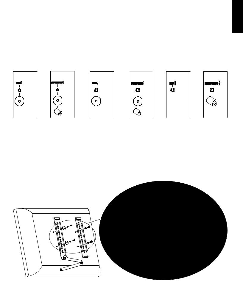
Supplied Parts and Hardware: Some parts not shown as actual size*
ENGLISH
(1) Wall Plate - a* |
(1) Locking Monitor Bracket - b* |
(1) Monitor Bracket - c* |
(3) Lag Bolts - d |
(3) Lag Bolt Washer - e |
(3) Concrete Anchor - f |
(4) M4 Lock Washer - g |
(4) M5 Lock Washer - h |
(4) M6 Lock Washer - i |
(4) M4/M5 Washer - j |
(4) M4/M5 Spacer - k |
(4) M6 Spacer - l |
(4) M4 x 10mm Monitor Bolt - m |
(4) M5 x 12mm Monitor Bolt - n |
(4) M6 x 12mm Monitor Bolt - o |
(4) M4 x 30mm Monitor Bolt - p |
(4) M5 x 30mm Monitor Bolt - q |
(4) M6 x 35mm Monitor Bolt - r |

ENGLISH
Step 1: Mount the Wall Plate: Wood Stud, Brick, Solid Concrete, and Concrete Block mounting options are provided.
Wood Stud Mounting: The Wall Plate (a) must be mounted to a wood stud. Use a high quality stud sensor to locate a stud. Pre-drill a 2.5” deep hole at the desired height in the stud using a 3/16” drill bit. Make sure the hole is in the center area of the stud. Use the Wall Plate as a template to mark the location of the second hole. Make sure the Wall Plate is level and drill 2.5” a deep hole using the 3/16” drill bit in the marked location. Attach the Wall Plate to the wall using two Lag Bolts (d) and two Lag Bolt Washers (e). Make sure the Wall Plate is oriented so the flat surface in the center of the plate is against the wall as shown in Diagram 1a.
Warning: DO NOT OVERTIGHTEN THE LAG BOLTS! Tighten Lag Bolts only until the Lag Bolt Washer is pulled firmly against the Wall Plate.
Diagram 1a
d e
a 
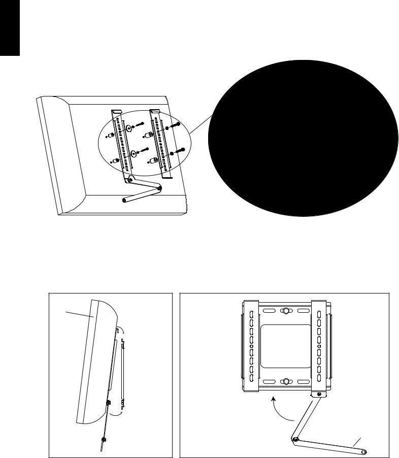
Brick, Solid Concrete and Concrete Block Mounting: Use the Wall Plate (a) as a template to mark 3 hole locations on the wall. Always locate Concrete Anchors (f) in the brick, block, or concrete. Never drill into the mortar between blocks! The two top holes should be as far to the outside of the Wall Plate as possible. The bottom hole should be in the center. Make sure theWall Plate is level. Carefully pre-Drill these holes with a 1/2” masonry bit to at least 2.5” in depth. Insert a Concrete anchor into each of these holes. Make sure the anchor is seated completely flush with the concrete surface even if there is a layer of drywall or other material in front. Attach the Wall Plate to the wall using 3 Lag Bolts (d) and 3 Lag Bolt Washers (e). See Diagram 1b for assistance.
Warning: DO NOT OVERTIGHTEN THE LAG BOLTS! Tighten Lag Bolts only until the Lag Bolt Washer is pulled firmly against the Wall Plate.
Diagram 1b
d e
a 
Step 2: Select the Appropriate Hardware for your television
Always make sure the television is unplugged before threading any bolt into the back panel!
Thread bolts carefully into your television by hand before tightening. If you feel resistance, remove the bolt immediately! If you are unable to find appropriate hardware for your television, consult a local hardware store or call Sanus Systems.
Locate the threaded inserts on the back of your flat panel television and determine which of the provided Bolts is the correct diameter. To test each diameter, thread the Bolts carefully into your television by hand until you find the diameter that correctly fits.
Next, determine the correct length of the required Bolt. Televisions with a flat back will require one of the shorter Bolts and no spacer. Some televisions have a curve, recess, or other obstruction on the back. This may require a longer Bolt along with a Spacer placed between the television and the Monitor Bracket.
Once you have the correct bolt picked out, you can follow the diagrams below to see what additional hardware you will need to mount the Monitor Brackets (b,c) to your television. For a television with a flat back, see Step 3 for installation instructions. For all other instances, see Step 4.
Hardware Diagrams: Parts are scaled.
M4 x 10 |
M4 x 30 |
M5 x 12 |
M5 x 30 |
M6 x 12 |
M6 x 35 |
m |
p |
n |
q |
o |
r |
g |
g |
h |
h |
i |
i |
j |
j |
j |
j |
|
l |
|
k |
|
k |
|
|
ENGLISH
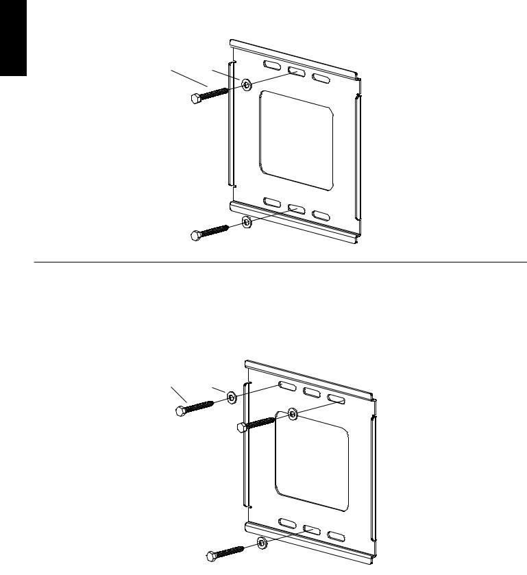
Step 3: Attach Monitor Brackets to a television with a flat back
Make sure the Locking Monitor Bracket (b) is located on the left side as shown in Diagram 3. If your TV requires either an M4 or M5 diameter bolt, thread a M4 x 10mm (m) or M5 x 12mm Bolt (n) through the appropriate Lock Washer (g,h), an M4/M5 washer, the Monitor Bracket (b,c) and into the TV as shown on the left side of the Detailed View of Diagram 3. If you have determined that your TV requires an M6 diameter bolt, thread an M6 x 12mm Bolt (o) through a Lock Washer (i), the Monitor Brackets, and into the TV, as shown on the right side of the Detailed View of Diagram 3 for Assistance. Proceed to tighten the Bolts firmly with a phillips screw driver.
Detailed View
Diagram 3
|
m,n |
g,h |
o |
j |
i |
b |
c |
ENGLISH
Step 4: Attach Monitor Brackets to a television with a curve, recess, or other obstuction on the back.
Make sure the Locking Monitor Bracket (b) is located on the left side as shown in Diagram 4. If your TV requires either a M4 or M5 diameter bolt, thread a M4 x 30mm (p) or a M5 x 30mm Bolt (q) through the appropriate Lock Washer (g,h), an M4/M5 Washer (j), the Monitor Bracket (b,c), a M4/M5 Spacer (k) and into the TV as shown on the left side of the Detailed View of Diagram 4. If you determined that your TV requires a Bolt with a M6 Diameter, thread a M6 x 35 (r) Bolt through a Lock Washer (i), the Monitor Bracket, a M6 Spacer (l) and into the TV, as shown on the right side the Detailed View of Diagram 4 for assistance. Proceed to tighten the Bolts firmly with a phillips screw driver. Detailed View
Diagram 4
|
|
p,q |
|
|
|
|
g,h |
i |
r |
|
j |
|
|
|
k |
b |
l |
c |
|
Step 5: Hang television on the Wall Plate
Warning: Some televisions may require 2 people to lift! Sanus is not responsible for personal injury or product damage.
First hook the Monitor Brackets (b,c) over the top of the Wall Plate (a), then let the bottom of the Monitor Brackets rotate in under the bottom of the Wall Plate as shown in Diagram 5a. Lock the television to the Wall Plate by moving the handle upward so the tab on the handle goes behind the bottom of the Wall Plate as shown in Diagram 5b. Fold the handle extension up so that it hides behind the television.
Diagram 5a |
Diagram 5b |
TV
 a
a
wall
tab

extension handle

L A UNI Ó N D E FORMA Y FU N C I Ó N
Instrucciones de armado del modelo VM300
Gracias por elegir el soporte de pared Vision Mount de Sanus Systems. El modelo VM300 ha sido diseñado para montar televisores con pantalla plana de 101,6 cm (40 pulg.) con un peso de hasta 36,3 kg (80 lb) en una pared vertical. Este modelo permite fijar el televisor a apenas 1,3 cm (0,5 pulg.) de la pared.
Advertencia de seguridad: Si no entiende estas instrucciones o si tiene alguna duda con respecto a la seguridad de la instalación, llame a un contratista calificado o llámenos al 800.359.5520 (en EE.UU.) o al 31 (0) 20 5708938 (en Europa). También nos puede visitar en nuestro sitio www.sanus.com. Revise cuidadosamente para asegurarse de que no hayan piezas faltantes o defectuosas. Nuestros representantes del servicio al cliente pueden ayudarle a responder sus preguntas sobre la instalación o con respecto a las piezas faltantes o defectuosas. Las piezas de repuesto para los productos comprados a través de un distribuidor autorizado se enviarán directamente a usted. Nunca use piezas que presenten algún defecto. La instalación incorrecta puede provocar daño o lesiones graves. No use este producto para fines que no estén especificados explícitamente por Sanus Systems. Sanus Systems no se hace responsable de los daños ni de las lesiones causadas por el montaje, armado o uso incorrectos. Sírvase llamar a Sanus Systems antes de devolver los productos al punto de compra.
Herramientas necesarias: Taladro, broca de 0,5 cm (3/16 pulg.), (broca para concreto de 1,3 cm (1/2 pulg.) para instalaciones sobre ladrillo, concreto o bloques de hormigón), juego de llaves mecánicas, destornillador philips
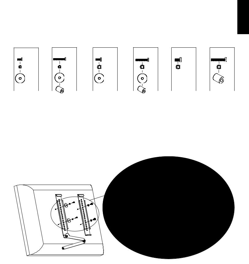
Piezas y tornillería suministradas: Algunas piezas no se muestran del tamaño real*
ESPAÑOL
(1) Placa adaptadora - a* |
(1) Soporte de bloqueo del monitor - b* |
(1) Soporte de monitor - c* |
(3) Tirafondo - d |
(3) Arandela de tirafondo - e |
(3) Anclaje para concreto - f |
(4) Arandela de seguridad M4 - g |
(4) Arandela de seguridad M5 - h |
(4) Arandela de seguridad M6 - i |
(4) Arandela M4/M5 - j |
(4) Espaciador M4/M5 - k |
(4) Espaciador M6 - l |
|||
|
|
|
|
|
|
|
|
|
|
|
|
|
|
|
|
|
|
|
|
|
|
|
|
(4) Perno de monitor M4 x 10 mm - m |
(4) Perno de monitor M5 x 12 mm - n (4) Perno de monitor M6 x 12 mm - o |
(4) Perno de monitor M4 x 30 mm - p |
(4) Perno de monitor M5 x 30 mm - q (4) Perno de monitor M6 x 35 mm - r |
ESPAÑOL
Paso 1: Montar la placa de pared: Se proporcionan opciones para montaje sobre pie derecho de madera, ladrillo, concreto sólido y bloque de hormigón.
Montaje sobre pie derecho de madera: La placa de pared (a) se debe montar a un pie derecho de madera. Utilizar un detector de vigas de alta calidad para localizar el pie derecho. Perforar con antelación un agujero profundo de 6,4 cm (2,5 pulg.) en la altura deseada del pie derecho utilizando una broca de 0,5 cm (3/16 pulg.). Asegurarse de que el agujero quede bien centrado en el pie derecho. Utilizar la placa de pared como una plantilla para marcar la posición del segundo agujero. Asegurarse que la placa de pared esté nivelada y perforar un agujero profundo de 6,4 cm (2,5 pulg.) utilizando una broca de 0,5 cm (3/16 pulg.) en el punto marcado. Conectar la placa en la pared utilizando dos tirafondos (d) y dos arandelas de tirafondo (e). Asegurarse que la placa de pared esté orientada de manera que la superficie plana del centro de la placa quede contra la pared, como se ilustra en el diagrama 1a.
Advertencia: ¡NO APRETAR DEMASIADO LOS TIRAFONDOS! Apretar los tirafondos sólo hasta que la arandela quede bien firme contra la placa de pared. 

Diagrama 1a d e
a 
Montaje en ladrillo, concreto y bloque de hormigón: Utilizar la placa de pared (a) como una plantilla para marcar las 3 posiciones de los agujeros en la pared. Siempre poner anclajes para concreto (f) en el ladrillo, bloque o concreto. ¡Nunca perforar en el cemento entre los bloques! Los dos agujeros superiores deben quedar lo más afuera posible de la placa de pared. El agujero inferior debe quedar en el centro. Asegurarse que la placa de pared esté nivelada. Perforar cuidadosamente estos agujeros con una broca para concreto de 6,4 cm (1/2 pulg.) a una profundidad mínima de 6,4 cm (2,5 pulg.). Insertar un anclaje para concreto en cada uno de estos agujeros. Asegurarse de que el anclaje quede asentado completamente a ras con la superficie de concreto, incluso si hubiera una capa de yeso o de otro material encima. Conectar la placa en la pared utilizando 3 tirafondos (d) y 3 arandelas de tirafondo (e). Ver el diagrama 1b para más ayuda.
Advertencia: ¡NO APRETAR DEMASIADO LOS TIRAFONDOS! Apretar los tirafondos sólo hasta que la arandela quede bien firme contra la placa de pared.
Diagrama 1b |
d |
e |
a 
Paso 2: Seleccionar la tornillería correcta para el televisor
¡Siempre asegurarse que el televisor esté desenchufado antes de pasar cualquier perno por el panel trasero!
Cuidadosamente enroscar los pernos a mano antes de apretarlos en el televisor. ¡Si siente alguna resistencia, retirar el perno inmediatamente! Si no puede encontrar la tornillería correcta para su televisor, consultar en una ferretería local o llamar a Sanus Systems.
Ubicar los insertos roscados en la parte trasera del televisor con pantalla plana, y determinar cuál de los pernos suministrados es el de diámetro correcto. Para probar el diámetro, enroscar los pernos a mano en el televisor hasta encontrar el diámetro que encaje correctamente.
Luego, determinar el largo correcto del perno requerido. Los televisores con la parte trasera plana requerirán los pernos cortos y no necesitan espaciador. Algunos televisores tienen la parte trasera curvada, hendida o con otro tipo de obstrucción. Esto puede requerir un perno más largo junto con un espaciador que se debe colocar entre el televisor y el soporte de monitor.
Una vez que se tenga seleccionado el perno correcto, se pueden seguir los diagramas de más abajo para ver la tornillería adicional que se necesitará para montar los soportes de monitor (b, c) en el televisor. Para un televisor con la parte trasera plana, ver el paso 3 para las instrucciones de instalación. Para todas las demás instancias, ver el paso 4.
Diagramas de tornillería: Las piezas se ilustran a escala.
M4 x 10 |
M4 x 30 |
M5 x 12 |
M5 x 30 |
M6 x 12 |
M6 x 35 |
m |
p |
n |
q |
o |
r |
g |
g |
h |
h |
i |
i |
j |
j |
j |
j |
|
l |
|
k |
|
k |
|
|
ESPAÑOL
Paso 3: Conectar los soportes de monitor a un televisor con la parte trasera plana
Asegurarse de que el soporte de bloqueo del monitor (b) quede ubicado en el lado izquierdo, como se ilustra en el diagrama 3. Si el televisor requiere de un perno de diámetro M4 ó M5, pasar un perno M4 x 10 mm (m) o M5 x 12 mm (n) a través de la arandela de segu ridad (g, h) correspondiente, una arandela M4/M5, el soporte de monitor (b, c) e insertarlo en el televisor, como se ilustra en el lado izquierdo de la vista detallada del diagrama 3. Si se determina que el televisor requiere de un perno con un diámetro M6, pasar un perno M6 x 12 mm (o) a través de la arandela de seguridad (i), los soportes de monitor e insertarlo en el televisor, como se ilustra en el lado derecho de la vista detallada del diagrama 3. Proceder a apretar firmemente los pernos con un destornillador phillips.
Vista detallada
Diagrama 3
|
m, n |
g, h |
o |
j |
i |
b |
c |

ESPAÑOL
Paso 4: Conectar los soportes de monitor a un televisor con la parte trasera curvada, hendida o con otro tipo de obstrucción.
Asegurarse de que el soporte de bloqueo del monitor (b) quede ubicado en el lado izquierdo, como se ilustra en el diagrama 4. Si el televisor requiere de un perno de diámetro M4 ó M5, pasar un perno M4 x 30 mm (p) o M5 x 30 mm (q) a través de la arandela de seguridad (g, h) correspondiente, una arandela M4/M5 (j), el soporte de monitor (b, c), un espaciador M4/M5 (k) e insertarlo en el televisor, como se ilustra en el lado izquierdo de la vista detallada del diagrama 4. Si se determina que el televisor requiere de un perno con un diámetro M6, pasar un perno M6 x 35 (r) a través de la arandela de seguridad (i), el soporte de monitor, un espaciador M6 (l) e insertarlo en el televisor, como se ilustra en el lado derecho de la vista detallada del diagrama 4. Proceder a apretar firmemente los pernos con un destornillador phillips.
Vista detallada
Diagrama 4
|
|
p, q |
|
|
|
|
g, h |
i |
r |
|
j |
|
|
|
k |
b |
l |
c |
|
Paso 5: Colgar el televisor en la placa de pared
Advertencia: ¡Se requieren dos personas para levantar algunos televisores! Sanus no es responsable por lesiones personales ni daño al producto.
Primero enganchar los soportes de monitor (b, c) en la parte superior de la placa de pared (a), luego dejar que la base de los soportes de monitor giren debajo de la placa de pared, como se ilustra en el diagrama 5a. Trabar el televisor en la placa de pared moviendo la manija hacia arriba, de manera que la pestaña de la manija quede detrás de la parte posterior de la placa de pared, como se ilustra en el diagrama 5b. Plegar la extensión de la manija de manera que quede oculta detrás del televisor.
Diagrama 5a |
Diagrama 5b |
TV
 a
a
pared
 pestaña

extensión de manija
DIE EINHEIT VON FORM UND FUNKTION
Montageanweisungen für das Modell VM300
Wir freuen uns, dass Sie sich für eine Vision Mount-Wandhalterung von Sanus Systems entschieden haben. Das Gerät VM300 ist für die Montage von LCD-Flachbildfernsehern mit einer Bildschirmdiagonale von 101,6 cm (40") und einem Gewicht von bis 36,3 kg (80 lb) an einer vertikalen Wand vorgesehen. Der Fernseher kann in einem Abstand von nur 1,3 cm (1/2") von der Wand montiert werden.
Sicherheitshinweis: Wenn Sie diese Anweisungen nicht verstehen oder Zweifel an der Sicherheit der Montage haben, rufen Sie einen Fachmann an oder kontaktieren Sie Sanus Systems telefonisch unter +1-800-359-5520 (USA) oder +31-(0)20-570-8938 (Europa). Oder besuchen Sie uns im Internet unter www.sanus.com. Überprüfen Sie die Montage sorgfältig, um sicherzugehen, dass keine Teile fehlen oder beschädigt sind. Unsere Kundendienstmitarbeiter können Ihnen bei Fragen zur Montage und bei fehlenden oder beschädigten Teilen schnell weiterhelfen. Ersatzteile für bei autorisierten Fachhändlern gekaufte Sanus-Produkte werden direkt an Ihre Adresse versendet. Verwenden Sie niemals beschädigte Teile! Unsachgemäße Montage kann Schäden am Gerät und schwere Verletzungen hervorrufen! Verwenden Sie das Produkt nicht für andere als von Sanus Systems explizit genannte Zwecke. Sanus Systems haftet nicht für Schäden oder Verletzungen, die durch unsachgemäße Montage, fehlerhaften Zusammenbau oder unsachgemäße Nutzung entstehen. Bitte rufen Sie Sanus Systems an, bevor Sie Produkte beim Händler reklamieren.
Erforderliche Werkzeuge: Bohrmaschine, Bohrer 0,5 cm (3/16") (Steinbohrer 1,3 cm (1/2") für Ziegel, Beton oder Betonsteine), Maulschlüsselsatz , Kreuzschlitzschraubendreher
Mitgelieferte Teile und Zubehör: Einige Teile sind nicht maßstäblich dargestellt.*
DEUTSCH
(1) Wandplatte – a* |
(1) Verriegelungsmonitorklammer – b* |
(1) Monitorklammer – c* |
(3) |
Holzschrauben – d |
(3) Holzschraubenunterlegscheibe – e |
(3) Betondübel – f |
(4) |
Sicherungsscheibe M4 – g |
(4) Sicherungsscheibe M5 – h |
(4) Sicherungsscheibe M6 – i |
(4) Unterlegscheibe M4/M5 – j |
(4) Distanzstück M4/M5 – k |
(4) Distanzstück M6 – l |
|||
|
|
|
|
|
|
|
|
|
|
|
|
|
|
|
|
|
|
|
|
|
|
|
|
(4) Monitorschraube M4 x 10 mm – m (4) Monitorschraube M5 x 12 mm – n |
(4) Monitorschraube M6 x 12 mm – o |
(4) Monitorschraube M4 x 30 mm – p (4) Monitorschraube M5 x 30 mm – q |
(4) Monitorschraube M6 x 35 mm – r |
 Loading...