


|
Modu-Flo® System |
||
BYLUBRIQUIP® |
Operation and Service Instructions |
||
|
|
|
|
|
|
Bulletin 42000 |
|
|
|
|
|
|
|
|
|
R
Modular
Pumping
Packages
© LUBRIQUIP, INC., 1988. All Rights Reserved.
Revised November 2005

Modu-Flo® System |
42000 |
TABLE OF CONTENTS
Section/Para |
Page |
|
1 |
INTRODUCTION .............................................. |
1-1 |
1.1 |
GENERAL ............................................................. |
1-1 |
1.2 |
GENERAL SYSTEM OPERATION ......................... |
1-2 |
2 |
RESERVOIRS AND TANKS ............................. |
2-1 |
2.1 |
DESCRIPTION...................................................... |
2-1 |
2.2 |
MOUNTING INSTRUCTIONS ............................... |
2-1 |
2.3 |
PREPARATION FOR USE ..................................... |
2-2 |
2.4 |
GREASE RESERVOIR MAINTENANCE |
|
|
(OPTIONS GP1 THROUGH GP5 AND GM1 |
|
|
THROUGH GM4) .................................................. |
2-3 |
2.5 |
OIL RESERVOIR MAINTENANCE |
|
|
(OPTIONS OP1 THROUGH OP4) ........................ |
2-7 |
2.6 |
OIL TANK MAINTENANCE |
|
|
(OPTIONS T1, T2 and T3) .................................. |
2-11 |
3 |
PUMPS............................................................ |
3-1 |
3.1 |
DESCRIPTION...................................................... |
3-1 |
3.2 |
PREPARATION FOR USE ..................................... |
3-3 |
3.3 |
PNEUMATIC PUMP MAINTENANCE |
|
|
(OPTIONS A1 THROUGH A6) .............................. |
3-3 |
3.4 |
HYDRAULIC PUMP MAINTENANCE |
|
|
(OPTIONS H1 AND H3) ........................................ |
3-9 |
3.5 |
HYDRAULIC PUMP MAINTENANCE |
|
|
(OPTION H2)....................................................... |
3-13 |
4 |
MANIFOLDS.................................................... |
4-1 |
4.1 |
DESCRIPTION...................................................... |
4-1 |
4.2 |
PREPARATION FOR USE ..................................... |
4-1 |
4.3 |
MAINTENANCE ..................................................... |
4-1 |
5 |
LOW-LEVEL SWITCHES ................................ |
5-1 |
5.1 |
DESCRIPTION...................................................... |
5-1 |
5.2. |
MOUNTING INSTRUCTIONS ............................... |
5-1 |
Section/Para |
Page |
||
5.3 |
OIL TANK AND RESERVOIR 15 AMP |
|
|
|
LOW-LEVELASSEMBLY MAINTENANCE |
|
|
|
(OPTIONS L1, L2 and L3) .................................... |
|
5-2 |
5.4 |
OIL TANK RESERVOIR 10-WATT LOW-LEVEL |
|
|
|
ASSEMBLY MAINTENANCE (OPTIONS L5, L6 |
|
|
|
AND L7) ................................................................ |
|
5-4 |
5.5 |
GREASE RESERVOIR LOW-LEVELASSEMBLY |
|
|
|
MAINTENANCE (OPTION L4) ............................... |
|
5-5 |
6 |
HIGH-PRESSURE AND BLOWOUT |
|
|
SWITCHES ...................................................... |
6-1 |
6.1 |
DESCRIPTION ...................................................... |
6-1 |
6.2 |
HIGH-PRESSURE SWITCH ADJUSTMENT ........ |
6-2 |
6.3 |
MOUNTING INSTRUCTIONS ............................... |
6-3 |
6.4 |
HIGH-PRESSURE SWITCH MAINTENANCE |
|
|
(OPTION P1) ......................................................... |
6-3 |
6.5 |
RESERVOIR BLOWOUT SWITCH MAINTE- |
|
|
NANCE (OPTIONS P2 and P3) ............................ |
6-4 |
6.6 |
TANK BLOWOUT SWITCH MAINTENANCE |
|
|
(OPTION P4) ......................................................... |
6-6 |
7 |
PNEUMATIC SOLENOID OPTIONS ................ |
7-1 |
8 |
CONTROLLERS .............................................. |
8-1 |
8.1 |
DESCRIPTION ...................................................... |
8-1 |
8.2 |
WIRING ................................................................. |
8-2 |
9 |
SYSTEM OPERATION ..................................... |
9-1 |
9.1 |
GENERAL ............................................................. |
9-1 |
9.2 |
SYSTEM INFORMATION ....................................... |
9-1 |
9.3 |
OPERATING TIPS ................................................. |
9-1 |
9.4 |
MATERIAL CONSIDERATIONS ............................. |
9-2 |
10 |
TROUBLESHOOTING ................................... |
10-1 |
10.1 |
GENERAL ........................................................... |
10-1 |
LIST OF ILLUSTRATIONS
Number |
Title |
Page |
Number |
Title |
Page |
1-1. |
Modu-Flo Functional Schematic ......................... |
1-3 |
5-2. |
Oil Tank and Reservoir 10-Watt |
|
2-1. |
Grease Reservoir - Exploded View ..................... |
2-5 |
|
Low-Level Assembly ........................................... |
5-5 |
2-2. |
Oil Reservoir - Exploded View ............................ |
2-9 |
5-3. |
Grease Reservoir Low-Level Assembly ............. |
5-6 |
2-3. |
Oil Tank - Exploded View .................................. |
2-13 |
6-1. |
High-Pressure Switch ......................................... |
6-2 |
3-1. |
Typical Pump Operation ...................................... |
3-2 |
6-2. |
High-Pressure Switch (Rear View) ..................... |
6-4 |
3-2. |
Pneumatic Pump, Exploded View ...................... |
3-7 |
6-3. |
Reservoir Blowout Switch Assembly (Front |
|
3-3. |
Hydraulic Pump Options H1 and H3 - |
|
|
View) .................................................................... |
6-5 |
|
Exploded View ................................................... |
3-11 |
6-4. |
Tank Blowout Switch Assembly .......................... |
6-7 |
3-4. |
Hydraulic Pump Option H2 - Exploded View .... |
3-15 |
7-1. |
Pneumatic Solenoid ........................................... |
7-1 |
4-1. |
Typical Manifold Assembly .................................. |
4-3 |
8-1. |
DC Timer Wiring Schematic ............................... |
8-2 |
5-1. |
Oil Tank and Reservoir 15 Amp Low-Level |
|
8-2. |
AC Timer Wiring Schematic ................................ |
8-2 |
|
Assembly ............................................................ |
5-3 |
8-3. |
TC1000 Timer/Counter Wiring Schematic ......... |
8-3 |
|
|
|
8-4. |
WMP Maxi-Monitor Wiring Schematic ................. |
8-3 |
i
R

Modu-Flo® System |
42000 |
LIST OF TABLES
Number |
Title |
Page |
2-1. |
Reservoirs and Tanks ......................................... |
2-2 |
2-2. |
Grease Reservoir Parts List ............................... |
2-4 |
2-3. |
Oil Reservoir Parts Lists ..................................... |
2-8 |
2-4. |
Oil Tank Parts List ............................................. |
2-12 |
3-1. |
Pumps ................................................................. |
3-2 |
3-2. |
Pneumatic Pump Parts List ................................ |
3-5 |
3-3. |
Hydraulic Pump Options H1 and H3 |
|
|
Parts List ........................................................... |
3-10 |
3-4 |
Hydraulic Pump Option H2 Parts List ............... |
3-14 |
4-1. |
Operating Ports on Modu-Flo Manifolds ............. |
4-2 |
4-2. |
Manifolds and Manifold Accessories .................. |
4-2 |
5-1. |
Low-Level Switch Assemblies ........................... |
5-2 |
5-2. |
Oil Tank and Reservoir 15 Amp Low-Level |
|
|
Assemblies Parts List ........................................ |
5-3 |
Number |
Title |
Page |
5-3. |
Oil Tank and Reservoir 10-Watt Low-Level |
|
|
Assemblies Parts List ........................................ |
5-5 |
5-4. |
Grease Reservoir Low-Level Assembly |
|
|
Parts List ............................................................. |
5-6 |
6-1. |
Blowout Discs and Kits ....................................... |
6-1 |
6-2. |
High-Pressure and Blowout Switch |
|
|
Assemblies ......................................................... |
6-2 |
6-3. |
Pressure Switch Settings ................................... |
6-3 |
6-4. |
High-Pressure Switch Parts List ........................ |
6-4 |
6-5. |
Reservoir Blowout Switch Parts List .................. |
6-5 |
6-6. |
Tank Blowout Switch Parts List ........................... |
6-6 |
7-1. |
Pneumatic Solenoid Parts List ........................... |
7-1 |
10-1. |
Modu-Flo Troubleshooting ............................... |
10-1 |
R
ii

|
Modu-Flo® System |
|
|
|
42000 |
|
|
|
|
|
Modu–Flo® |
|
|
|
|
OPERATION AND |
|
|
|
|
|
SERVICE INSTRUCTIONS |
System |
|
|
|
|
|
|
|
|
|
|
SECTION 1 |
|
|
|
|
|
INTRODUCTION |
|
|
1.1 |
GENERAL................................................................... |
1-1 |
||
|
|
1.1.1 |
Standard Components ................................... |
1-1 |
|
|
|
1.1.2 |
Modu-Flo Options ........................................... |
1-1 |
|
|
1.2 |
GENERAL SYSTEM OPERATION .............................. |
1-1 |
||
1.1GENERAL
1.1.1 Standard Components. A wide choice of modular components may be assembled to meet a given application.
1.1.1.1 All Modu-Flo systems consist of the following components:
a.
b.
c.
1.1.2Modu-Flo Options.
1.1.2.1 Options which are available for any system include the following:
a. Low-level switches which mount to the reservoir or tank and provide a low-level fault signal to a customerdesignated component. Level switch options are described in Section 5.
b. High-pressure indicators which are installed into the pump outlet circuit and provide an over-pressure signal to external components. Pressure switch options are discussed in Section 6.
c. A pneumatic solenoid valve which mounts directly to the manifold. The solenoid valve is a three-way, normallyclosed type. Use of the solenoid allows the pump to be cycled by various controller options. The solenoid is equipped with a manual override button which may be used to simplify system testing, line filling and line bleeding.
d. Several types of controllers are used which can be adapted to the system. Controller options are discussed in Section 8. Controllers available are as follows:
(1)Timers which may be set to cycle the pump at given intervals. Both AC and DC models are available.
(2)A TC-1000 timer can operate the lube system on either a time or machine cycle basis. It is available in 12 or 24 VDC or 115 or 230 VAC.
(3)A WMP Maxi-Monitor which provides a dispense signal on either a time or machine cycle basis. The WMP also monitors and displays the status of the lube system it is controlling. The Maxi-Monitor is available in either 115 or 230 VAC.
1-1 |
R |

Modu-Flo® System |
42000 |
1.2GENERAL SYSTEM OPERATION
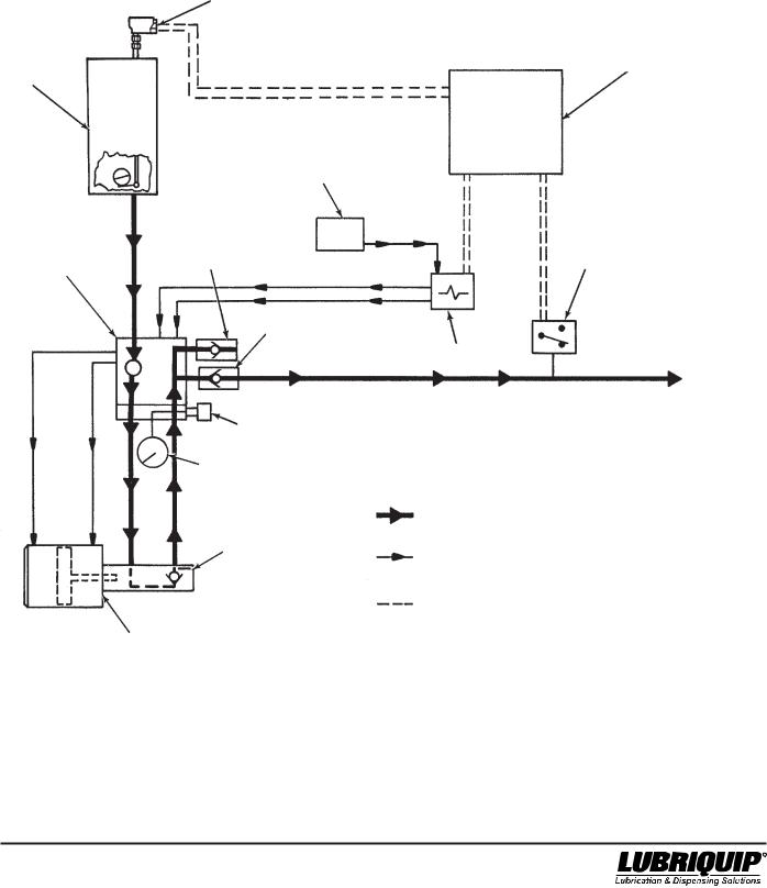
1.2.1 Figure 1-1 shows a functional schematic of a ModuFlo system.
1.2.1.1 The following steps outline the operating sequence of a Modu-Flo system:
a. Lubricant stored in the reservoir or tank flows to the manifold. The manifold may be mounted directly to the reservoir or tank, or it may be mounted on a wall.
b. The manifold directs lubricant into the pump to fill the pump chamber.
c. A controller energizes a solenoid valve to dispense and the solenoid sends air or hydraulic fluid to the manifold. Porting in the manifold directs the air or hydraulic fluid to the pump, causing the pump to dispense lube to the manifold outlet port.
d. When the controller releases the solenoid, air or hydraulic fluid is redirected, causing the pump to retract. On single-acting pneumatic pumps a spring pushes the pump to the retracted position.
e. Lubricant from the reservoir flows through the manifold and refills the empty chamber in the pump.
f. A pressure gauge, blowout disc, and high-pressure switch are options which may be connected to the output lube on the manifold. A signal from the pressure switch can be used to actuate an alarm or warning light.
g. Low-level switch options are available for all tanks or reservoirs. The switch provides an electrical signal when lubricant level is low.
R |
1-2 |
Modu-Flo® System |
42000 |
LOW LEVEL
SWITCH
RESERVOIR
OR TANK
PNEUMATIC/
HYDRAULIC SUPPLY
|
SYSTEM FILL |
MANIFOLD |
CHECK |
|
LUBE OUTLET
CHECK
BLOWOUT
ASSEMBLY
GAUGE
TEST/AIR
PURGE PORT
PUMP
CONTROLLER
PRESSURE
SWITCH
SOLENOID
LUBE LINES
PNEUMATIC/HYDRAULIC
LINES
ELECTRICAL LINES
Figure 1-1. Modu-Flo Functional Schematic
1-3/(1-4 Blank) |
R |

Modu-Flo® System |
42000 |
||
|
|
|
Modu–Flo® |
|
|
OPERATION AND |
|
|
|
SERVICE INSTRUCTIONS |
System |
|
|
|
|
|
|
SECTION 2 |
|
|
|
RESERVOIRS AND TANKS |
|
2.1 |
DESCRIPTION .......................................................... |
2-1 |
|
|
2.1.1 |
Reservoir Description ................................... |
2-1 |
|
2.1.2 |
Tank Description ........................................... |
2-1 |
|
2.1.3 |
Reservoirs and Tanks Available ................... |
2-1 |
2.2 |
MOUNTING INSTRUCTIONS ................................... |
2-1 |
|
2.3 |
PREPARATION FOR USE ......................................... |
2-2 |
|
|
2.3.1 Filling Oil Reservoirs and Tanks ................... |
2-2 |
|
|
2.3.2 |
Filling Grease Reservoirs ............................. |
2-2 |
2.4 |
GREASE RESERVOIR MAINTENANCE |
|
|
|
(OPTIONS GP1 THROUGH GP5 AND GM1 THROUGH |
|
|
|
GM4) |
.......................................................................... |
2-3 |
|
2.4.1 |
General .......................................................... |
2-3 |
|
2.4.2 .................... |
Grease Reservoir Maintenance |
2-3 |
|
2.4.3 .............Disassembly of Grease Reservoirs |
2-3 |
|
|
2.4.4 ...................Assembly of Grease Reservoirs |
2-3 |
|
2.1DESCRIPTION
2.1.1Reservoir Description. Reservoirs are cylindrical in shape and are used for either grease or oil lubricants. If a reservoir is to be used for grease it will be equipped with a spring-loaded follower which will apply pressure on the grease to force it into the pump. Reservoirs use cylinders made of metal or plastic. If a metal cylinder is used, the reservoir will be equipped with a level indicator to allow a visual check of lubricant level. Plastic cylinders are clear, allowing personnel to actually see the amount of lubricant present. The base of all reservoirs has the necessary tapped holes for either direct mounting of a manifold or for installing hose or tubing to a remote-located manifold.
2.1.2Tank Description. Tanks are rectangular weldments used for holding oil. All tanks are equipped with a sight glass to allow personnel to easily check the lubricant level. A pad mounted to the tank base provides the necessary tapped holes for either direct mounting of a manifold or for installing hose or tubing to a remote-located manifold.
2.1.3Reservoirs and Tanks Available. Table 2-1 lists the tanks and reservoirs available for use. Listings in the option column are used to identify the reservoir or tank selected when a Modu-Flo system is ordered. The option used is
|
2.4.5 Grease Reservoir Parts Lists |
....................... 2-3 |
|
2.5 |
OIL RESERVOIR MAINTENANCE |
|
|
|
(OPTIONS OP1 THROUGH OP4) ............................. |
2-7 |
|
|
2.5.1 |
General .......................................................... |
2-7 |
|
2.5.2 |
Oil Reservoir Maintenance ............................ |
2-7 |
|
2.5.3 Disassembly of Oil Reservoir ....................... |
2-7 |
|
|
2.5.4 Assembly of Oil Reservoir ............................. |
2-7 |
|
|
2.5.5 Oil Reservoir Parts Lists ............................... |
2-7 |
|
2.6 |
OIL TANK MAINTENANCE |
|
|
|
(OPTIONS T1, T2 and T3) ....................................... |
2-11 |
|
|
2.6.1 |
General ........................................................ |
2-11 |
|
2.6.2 |
Oil Tank Maintenance .................................. |
2-11 |
|
2.6.3 |
Disassembly of Oil Tanks ........................... |
2-11 |
|
2.6.4 Assembly of Oil Tanks ................................. |
2-11 |
|
|
2.6.5 |
Oil Tank Parts List ....................................... |
2-11 |
designated by the entry in the ordering code as shown below:
MPP - XXX - XXX - XX - XX - XX - XX - XX - XXX - XX
Reservoir Option
2.2MOUNTING INSTRUCTIONS
2.2.1 Reservoirs and tanks may be mounted to any vertical surface. All units have 7/16 inch holes for attaching bolts or screws. Cylindrical reservoirs have two holes, six inches apart, drilled in the base bracket. All tanks have four holes drilled in flanges according to the following rectangular dimensions:
9-7/8 wide by 7 inches high for T1 tanks 11-1/8 wide by 7 inches high for T2 tanks 16-3/8 wide by 7 inches high for T3 tanks
2.2.1.1 Make sure the mounting location allows clearance for any accessories attached to the tank or reservoir. Oil reservoirs and all tanks have a fill cup on the top. Make sure there is enough room above the fill cup to permit personnel to perform a filling operation without difficulty. Drill the required holes and attach the reservoir or tank to the vertical surface. Securely tighten all attaching hardware. Make sure that the reservoir or tank is level.
2-1 |
R |

Modu-Flo® System |
|
|
|
42000 |
||
|
|
Table 2-1. Reservoirs and Tanks |
|
|
|
|
|
|
|
|
|
||
Part Number |
|
Type (Use) |
Reservoir Capacity |
Option |
||
|
|
|
|
|
|
|
521-001-060 |
|
Tank (oil) |
12 |
pint |
(5.68 liters) |
T1 |
521-001-070 |
|
Tank (oil) |
24 |
pint |
(11.4 liters) |
T2 |
521-001-080 |
|
Tank (oil) |
40 |
pint |
(18.9 liters) |
T3 |
185-100-080 |
|
Reservoir, Plastic (oil) |
5 pint |
(2.37 liters) |
OP1 |
|
185-100-060 |
|
Reservoir, Plastic (oil) |
12 |
pint |
(5.68 liters) |
OP2 |
185-100-070 |
|
Reservoir, Plastic (oil) |
20 |
pint |
(9.46 liters) |
OP3 |
185-100-750 |
|
Reservoir, Plastic (oil) |
6 pint |
(2.84 liters) |
OP4 |
|
185-100-040 |
|
Reservoir, Plastic (grease) |
5 lbs |
(2.27 kg) |
GP1 |
|
185-100-000 |
|
Reservoir, Plastic (grease) |
12 lbs |
(5.44 kg) |
GP2 |
|
185-100-010 |
|
Reservoir, Plastic (grease) |
20 lbs |
(9.07 kg) |
GP3 |
|
185-100-760 |
|
Reservoir, Plastic (grease) |
6 lbs |
(2.72 kg) |
GP4 |
|
185-101-080 |
|
Reservoir, Plastic (grease) |
3 lbs |
(1.36 kg) |
GP5 |
|
185-100-050 |
|
Reservoir, Metal (grease) |
5 lbs |
(2.27 kg) |
GM1 |
|
185-100-020 |
|
Reservoir, Metal (grease) |
12 lbs |
(5.44 kg) |
GM2 |
|
185-100-030 |
|
Reservoir, Metal (grease) |
20 lbs |
(9.07 kg) |
GM3 |
|
185-100-770 |
* |
Reservoir, Metal (grease) |
6 lbs |
(2.72 kg) |
GM4 |
|
185-101-100 |
Reservoir, Plastic (grease) |
40 lbs |
(18.14 kg) |
-- |
||
185-101-110 |
* |
Reservoir, Plastic (grease) w/low level indicator |
40 |
lbs |
(18.14 kg) |
-- |
185-100-120 |
* |
Reservoir, Plastic (grease) w/low level micro switch |
40 |
lbs |
(18.14 kg) |
-- |
* These assemblies are not available through the normal MPP system, only by ordering the full part number.
2.3PREPARATION FOR USE
NOTE
Before filling any reservoir or tank, a manifold should be attached to the base. The manifold has a check valve built into it which will prevent the lubricant from dripping out of the reservoir or tank. If the system has a remote-located manifold, make sure there is hose or tubing connected from the bottom of the reservoir or tank to the remote manifold.
2.3.1Filling Oil Reservoirs and Tanks. Reservoirs and tanks for oil have a fill cup mounted on top. Wipe the area around the fill cup to avoid contamination during filling. Open the fill cup cap and slowly pour the oil into the fill cup. A strainer attached to the fill cup will remove large particles which may be present in the oil. When filling is complete, close fillcup cap and wipe any spillage.
2.3.2Filling Grease Reservoirs.
WARNING
If a high-pressure, high-volume supply pump is used to fill grease reservoirs, excess pressure may not be completely released by the bleed hole in the reservoir wall. This could cause the reservoir to fracture, exposing personnel to flying particles and lubricant. Safety glasses must be worn during filling operations and the supply pump must be turned off and disconnected when filling is complete.
2.3.2.1 Filling of grease reservoirs requires that an external supply source be connected to the fill stud located in the base of the reservoir. To avoid introducing air into the system, make sure there is enough grease in the supply source to fill
the reservoir without being disconnected. Operate the supply source at a steady speed to allow air-free filling of the reservoir. Too fast of a fill speed may result in air pockets. The level of grease is checked by visual means. In reservoirs with plastic cylinders, the grease level may be seen through the cylinder. Reservoirs with metal cylinders have a levelindicator rod mounted on the cap which will indicate when the fill is complete.
NOTE
Excess lube forced into the reservoir after it has reached full level will be vented from a bleed hole in the reservoir tube. (See Warning above.)
2.3.2.2 When filling is complete, turn off the supply source and disconnect it from the fill stud. A check valve in the fill stud will prevent lubricant from being forced back out. A plastic dust cap is attached to the fill stud and should be installed over the fill stud to keep dirt from entering the system.
NOTE
For first time grease filling, or if the grease reservoir has been allowed to go empty, open the petcock in the bottom right side of the reservoir. Slowly begin to fill the reservoir, allowing air trapped under follower to exhaust out the open petcock. When grease free of air flows from the petcock, close petcock and continue to fill the reservoir until follower is at vent hole in reservoir tube (any remaining air and small amount of grease will exit vent).
Loosen system mainline connection at pump outlet. Operate pump until lubricant free of air flows from outlet port. Tighten mainline connection at pump. Pump is now free of air.
Note, for extreme cases where the pump will not take a prime, it may be helpful to inject serveral
R |
2-2 |
Modu-Flo® System |
42000 |
|
|
|
|
ounces of heavy oil through the grease fill quick disconnect. The pump will then prime on oil pulling the grease behind it. If it becomes necessary to use this method, all injected oil should be discharged at the loosened system supply connection along with any air.
Refer to bulletin 12411 (Portable Filler-Pak) for manual operated fill pump.
2.4GREASE RESERVOIR MAINTENANCE (OPTIONS GP1 THROUGH GP5 AND GM1 THROUGH GM4)
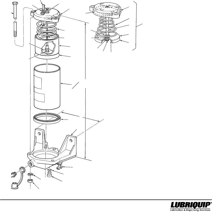
2.4.1General. Maintenance tips, disassembly, and assembly procedures for grease reservoirs are discussed in Paragraphs 2.4.2, 2.4.3 and 2.4.4. An exploded view of a typical grease reservoir is shown in Figure 2-1 and should be referred to during the discussion.
2.4.2Grease Reservoir Maintenance.
2.4.2.1 Maintenance on the grease reservoir consists of the steps described below:
a. Visually inspect the reservoir for lubricant leaking between reservoir tube (8, Figure 2-1) and base (10). This may indicate a bad gasket (9) or that the hex nuts (12) are not tight. Torque the nuts to 5 ft lbs. If the leakage continues, replace gasket (9). Check for cracks and nicks in tube (8). Replace the tube as required.
b. Visually inspect the reservoir tube (8) for dents which may restrict the movement of the follower cups (6 and 7). Replace the tube as required.
WARNING
Disconnect and lock out power before opening electrical enclosures or conduit connections. Serious injury may result from electrical shock.
2.4.3 Disassembly of Grease Reservoirs. Figure 2-1 shows a typical grease reservoir but does not include other Modu-Flo components which may be mounted to the reservoir. These components include the manifold, pump, level switches and high-pressure blowout switches. Disassembly of the reservoir may require that some of these components be removed. The manifold and pump do not normally require removal, but may be removed if desired. The level and blowout switches may or may not require removal, depending on the level of disassembly required. The electrical connections to the switches probably should be disconnected in order to remove various parts without restriction of movement by the electrical cord. The removal of these components is explained in other sections of the manual. Refer to the table of contents to find where the components are discussed.
2.4.3.1 The disassembly procedure may be performed with the reservoir mounted to the mounting surface. However, some mounting locations may be too restrictive to provide access to all components. If your particular installation requires dismounting of the reservoir, make sure the reservoir is drained of lubricant before removing the attaching hardware. This will reduce the weight of the reservoir and reduce
the chance of spillage. The disassembly procedure is as follows: WARNING
Do not attempt to remove retaining ring (2) or cable assembly (5) (Figure 2-1) (or retaining ring (25) or guide rod (5) for Option GP5). Injury could result from sudden expansion of spring
(4).
a. Slowly open petcock (11) and allow lubricant to be forced from the reservoir into a bucket or similar container. Remove fill stud (15) and petcock (11) if necessary. Properly dispose of emptied grease.
b. Remove hex nuts (12) and lockwashers (13) from tie rods (1). Remove tie rods (1) from cap (3).
c. Lift reservoir tube (8) from base (10) keeping reservoir cap (3) in position on top of the tube.
d. Slide reservoir tube (8) away from reservoir cap (3) until it is free of follower cup (7).
e. Remove gasket (9) from bottom of reservoir tube (8).
f. Further disassembly is only possible at the factory. If damage is apparent on the follower cups (6 and 7), cable assembly or guide rod (5), spring (4) or reservoir cap (3) the unit cannot be serviced and the reservoir assembly must be replaced.
2.4.4Assembly of Grease Reservoirs.
NOTE
Before assembly, lubricate followers and tube inner diameter with the lubricant which is used in the system.
2.4.4.1 Assemble the grease reservoir according to the following procedure:
a. Slide reservoir tube (8, Figure 2-1) over follower cup (7) being careful not to distort the follower cup lips. Slide reservoir tube (8) up until it contacts reservoir cap (3).
b. Install new gasket (9) on bottom of reservoir tube (8).
c. Place reservoir tube (8) with gasket (9) on base (10) and rotate reservoir cap (3) until holes in the cap line up with holes in the base (10).
d. Install tie rods (1) through holes in reservoir cap (3) and base (10).
e. Install lockwashers (13) and hex nuts (12) on tie rods (1) and torque to 5 ft lbs.
f. Install fill stud (15), dust cap (14) and petcock (11) in base. Make sure petcock (11) is in the closed position.
2.4.4.2 When the assembly steps listed in the above paragraph have been completed, any Modu-Flo components which were removed to ease disassembly should be reinstalled on the reservoir.
2.4.5 Grease Reservoir Parts Lists. Table 2-2 identifies the parts indexed in Figure 2-1.
2-3 |
R |

Modu-Flo® System |
|
|
|
|
|
|
42000 |
|
|
|
Table 2-2. Grease Reservoir Parts List |
|
|
||||
|
|
|
|
|
|
|
|
|
Item |
|
|
|
|
|
|
|
|
Number |
Part Number |
Description |
|
|
|
|
|
Quantity |
|
|
|
|
|
|
|
|
|
|
185-100-040 |
RESERVOIRASSEMBLY, |
5 lbs (2.27 kg), |
plastic (GP1) |
-- |
|||
|
185-100-000 |
RESERVOIRASSEMBLY, |
12 lbs (5.44 kg), |
plastic (GP2) |
-- |
|||
|
185-100-010 |
RESERVOIRASSEMBLY, |
20 lbs (9.07 kg), |
plastic (GP3) |
-- |
|||
|
185-100-760 |
RESERVOIRASSEMBLY, |
6 lbs (2.72 kg), |
plastic (GP4) |
-- |
|||
|
185-101-080 |
RESERVOIRASSEMBLY, |
3 lbs (1.36 kg), |
plastic (GP5) |
-- |
|||
|
185-100-050 |
RESERVOIRASSEMBLY, |
5 lbs (2.27 kg), |
metal (GM1) |
-- |
|||
|
185-100-020 |
RESERVOIRASSEMBLY, |
12 lbs (5.44 kg), |
metal (GM2) |
-- |
|||
|
185-100-030 |
RESERVOIRASSEMBLY, |
20 lbs (9.07 kg), |
metal (GM3) |
-- |
|||
|
185-100-770 |
RESERVOIRASSEMBLY, |
6 lbs (2.72 kg), |
metal (GM4) |
-- |
|||
1 |
415-700-272 |
BOLT, Tie (5 lb., 12 lb.) |
|
|
|
|
|
3 |
|
415-700-271 |
BOLT, Tie (20 lb.) |
|
|
|
|
|
3 |
|
415-700-273 |
BOLT, Tie (6 lb.) |
|
|
|
|
|
3 |
|
415-020-190 |
BOLT, Tie (3 lb.) |
|
|
|
|
|
3 |
2 |
|
RING, Retaining |
|
|
|
|
|
1 |
|
|
|
|
|
|
|||
3 |
|
CAP, Reservoir |
|
|
|
Items 2 through 7 |
1 |
|
4 |
|
SPRING |
|
|
|
1 |
||
5 |
|
CABLE ASSEMBLY |
|
|
|
are not serviceable |
1 |
|
|
|
GUIDE ROD |
|
|
|
by the user; replace |
1 |
|
6 |
|
GUIDE, Follower |
|
|
|
entire reservoir. |
1 |
|
7 |
|
CUP Seal |
|
|
|
|
|
1 |
9 |
501-423-001 |
|
|
|
|
1 |
||
GASKET (6” Tube) (3,6,12, 20 lb.) |
|
|
||||||
|
501-414-000 |
GASKET (4” Tube) (5 lb.) |
|
|
|
|
|
1 |
10 |
521-000-500 |
BASE, Aluminum (6” Tube) (6, 12, 20 lb.) |
|
1 |
||||
|
521-000-530 |
BASE (4” Tube) (5 lb.) |
|
|
|
|
|
1 |
|
521-008-950 |
BASE, Black (6” Tube) (3 lb.) |
|
|
|
|
|
1 |
11 |
501-970-000 |
PETCOCK |
|
|
|
|
|
1 |
12 |
410-040-020 |
NUT, Hex, 5/16-18 |
|
|
|
|
|
3 |
13 |
421-010-020 |
LOCKWASHER, 5/16 inch |
|
|
|
|
|
3 |
14 |
506-165-000 |
CAP, Dust |
|
|
|
|
|
1 |
15 |
506-189-001 |
Reservoir Fill Stud |
|
|
|
|
|
1 |
16 |
410-060-120 * |
NUT, Hex, 5/16-18 |
|
|
|
|
|
1 |
17 |
511-041-000 |
PLATE, Backup |
|
|
|
|
|
1 |
18 |
521-003-630 |
INDICATOR, Level (12 lb. Metal) |
|
1 |
||||
|
521-003-640 |
INDICATOR, Level (20 lb. Metal) |
|
1 |
||||
|
521-004-310 |
INDICATOR, Level (6 lb. Metal) |
|
1 |
||||
|
521-003-620 |
INDICATOR, Level (5 lb. Metal) |
|
1 |
||||
19 |
185-100-720+ |
TUBE, Reservoir, plastic, 13 inches (330.2mm) x |
|
1 |
||||
|
|
4 inches (100 mm) outer diameter (5 lb.) |
|
|
||||
|
185-100-730+ |
TUBE, Reservoir, plastic, 13 inches (330.2 mm) |
|
1 |
||||
|
|
x 6.0 inches (152.4 mm) outer diameter (12 lb.) |
|
|
||||
|
185-100-740+ |
TUBE, Reservoir, plastic, 20 inches (508 mm) x 6.0 |
1 |
|||||
|
|
inches (152.4 mm) outer diameter (20 lb.) |
|
|
||||
|
185-100-990+ |
TUBE, Reservoir, plastic, 8.5 inches (215.9 mm) x 6.0 |
1 |
|||||
|
|
inches (152.4 mm) outer diameter (6 lb.) |
|
|
||||
|
185-100-191+ |
TUBE, Reservoir, plastic, 5 inches (127 mm) x 6.0 |
|
1 |
||||
|
|
inches (152.4 mm) outer diameter (3 lb.) |
|
|
||||
|
185-101-187+ |
TUBE, Reservoir, metal, 13 inches (330.2 mm) x |
|
1 |
||||
|
|
4 inches (100 mm) outer diameter (5 lb.) |
|
|
||||
|
185-101-188+ |
TUBE, Reservoir, metal, 13 inches (330.2 mm) x 6.0 |
1 |
|||||
|
|
inches (152.4 mm) outer diameter (12 lb.) |
|
|
||||
|
185-101-189+ |
TUBE, Reservoir, metal, 20 inches (508 mm) x 6.0 1 |
|
|||||
|
|
inches (152.4 mm) outer diameter (20 lb.) |
|
|
||||
|
185-101-190+ |
TUBE, Reservoir, metal, 8.5 inches (215.9 mm) x 6.0 |
1 |
|||||
|
|
inches (152.4 mm) outer diameter ( 6 lb.) |
|
|
||||
*Mating fill coupler 506-322-000 (order separately)
+Reservoir Tube Kit includes gasket (item 9).
R |
2-4 |
Modu-Flo® System |
|
|
|
|
42000 |
||||||||
|
|
|
Table 2-2. Grease Reservoir Parts List - Continued |
||||||||||
Item |
|
|
|
|
|
|
|
|
|
|
|
|
|
Number |
Part Number |
Description |
|
|
|
|
Quantity |
||||||
20 |
439-060-181 |
GASKET, Top Vent (3 lb.) |
|
|
1 |
|
|||||||
21 |
|
BUSHING, Follower |
|
|
|
|
|
|
1 |
|
|||
22 |
|
WASHER, Follower |
|
Items 21 through 26 |
1 |
|
|||||||
23 |
|
WASHER, Support |
|
1 |
|
||||||||
|
|
are not serviceable |
|
||||||||||
24 |
|
NUT, Jam, 3/4-16 |
|
1 |
|
||||||||
|
|
by the user; replace |
|
||||||||||
25 |
|
O-RING |
|
entire reservoir. |
1 |
|
|||||||
26 |
|
RING, Retaining |
|
|
|
|
1 |
|
|||||
27 |
527-000-230 |
PLUG, Low Level (3 |
lb.) |
|
|
|
|
1 |
|
||||
28 |
527-000-240 |
GASKET (3 lb.) |
|
|
|
|
1 |
|
|||||
|
|
|
NOTE: |
|
|
|
|
|
|
|
|
||
|
|
USED ON METAL |
|
|
|
|
|
|
|
|
|||
|
|
RESERVOIRS ONLY |
|
|
|
|
|
|
|
|
|||
|
|
18 |
2 |
|
|
|
|
|
3 |
|
|
|
|
1 |
|
3 |
|
|
|
|
|
|
|
|
|
||
|
|
|
|
|
|
|
|
|
|
|
|||
|
20 |
|
|
|
|
|
|
|
|
||||
|
|
|
|
|
|
4 |
|
|
FOR |
||||
|
|
|
|
|
|
|
|
|
|
|
|||
|
|
|
|
|
|
|
|
|
5 |
|
|
OPTION |
|
|
|
|
|
|
|
|
|
|
|
|
GP5 |
||
|
|
|
4 |
|
|
24 |
|
22 |
|
|
ONLY |
||
|
|
|
5 |
|
|
25 |
|
|
|
|
|
||
|
|
|
|
|
|
|
|
|
|
|
|||
|
|
17 |
6 |
|
|
|
|
|
7 |
|
|
|
|
|
|
|
|
|
21 |
|
|
|
|
|
|
||
|
|
|
|
|
|
26 |
23 |
|
|
|
|
||
|
|
16 |
7 |
|
|
|
|
|
|
|
|
||
|
|
|
|
|
|
|
|
|
|
|
WARNING |
|
|
|
|
|
|
|
|
|
|
|
|
|
|
|
|
19+ |
|
8 |
B |
|
Do not attempt to remove retaining ring (2) or cable assembly (5), (Figure 2-1) (or retaining ring (26) or guide rod (5) for Option GP5).
Injury could result from sudden expansion of spring (4).
15*
13
14
12
9 |
A |
|
|
|
10 |
11
28
27
|
|
DIMENSIONS |
|
|
OPTION |
|
A |
|
B |
|
|
|||
GP1, GM1, |
|
7.25 inches |
|
15 inches |
GP2, GM2 |
|
(184 mm) |
|
(381 mm) |
GP3, GM3 |
|
7.25 inches |
|
22 inches |
|
|
(184 mm) |
|
(559 mm) |
GP4, GM4 |
|
7.25 inches |
|
10.5 inches |
|
|
(184 mm) |
|
(267 mm) |
GP5 |
|
7.25 inches |
|
6.87 inches |
|
|
(184 mm) |
|
(174 mm) |
|
|
|
|
|
* Mating fill coupler 506-322-000 (order separately) + Reservoir Tube Kit includes gasket (item 9).
Figure 2-1. Grease Reservoir - Exploded View
2-5/(2-6 Blank) |
R |

|
|
® System |
|
|
42000 |
|||||
2.5 |
OIL RESERVOIR MAINTENANCE |
is drained of lubricant before removing the attaching hard- |
||||||||
|
|
(OPTIONS OP1 THROUGH OP4) |
ware. This will reduce the weight of the reservoir and reduce |
|||||||
|
|
the chance of spillage. The disassembly procedure is as |
||||||||
2.5.1 |
General. Maintenance tips, disassembly, and as- |
follows: |
||||||||
|
|
|
||||||||
sembly procedures for oil reservoirs are discussed in Para- |
a. |
Remove pipe plug (4, Figure 2-2) from base (8) and |
||||||||
graphs 2.5.2, 2.5.3 and 2.5.4. An exploded view of a typical oil |
||||||||||
|
allow oil to drain from reservoir into bucket or similar |
|||||||||
reservoir is shown in Figure 2-2 and should be referred to |
|
|||||||||
|
container. Properly dispose of emptied oil. |
|||||||||
during the discussion. |
|
|||||||||
|
|
|
||||||||
2.5.2 |
Oil Reservoir Maintenance. |
b. |
Remove three hex nuts (9) and three lockwashers (10) |
|||||||
|
from tie rods (1). Remove tie rods (1) from reservoir cap |
|||||||||
|
|
|
|
|
|
|
|
|||
2.5.2.1 Maintenance on the oil reservoir consists of the |
|
(5). |
||||||||
following: |
c. |
Remove reservoir cap (5) from reservoir tube (6). |
||||||||
a. Visually check for oil leakage between reservoir tube (6, |
||||||||||
d. |
Remove fill screen (2) from fill cup (3) and clean screen. |
|||||||||
|
Figure 2-2) and base (8). Leakage may indicate that the |
|||||||||
|
gasket (7) is defective or that nuts (9) are not tight. |
e. |
Remove reservoir tube (6) from base (8). |
|||||||
|
Torque nuts (9) to 5 ft lbs. If leakage continues, replace |
|||||||||
|
gasket (7). Check for cracks and nicks on tube (6). |
f. |
Remove and discard gasket (7) from reservoir tube (6). |
|||||||
|
Replace the tube as required. |
|||||||||
|
|
|
|
|||||||
|
Visually check screen (2) in fill cup (3) to make sure it is |
2.5.4 |
Assembly of Oil Reservoir. |
|||||||
|
|
|
|
|||||||
|
not clogged. If necessary, remove the screen for clean- |
|
|
NOTE |
||||||
|
ing. |
|
|
Before assembly, lubricate followers and tube |
||||||
|
|
|
|
|
|
|
|
|
||
|
Check reservoir bottom for debris. Clean as required. |
|
|
inner diameter with the lubricant which is used |
||||||
|
|
|
|
|
|
|
|
|
in the system. |
|
|
|
|
|
|
WARNING |
|
2.5.4.1 Assemble the oil reservoir according to the follow- |
|||
|
|
|
|
|
|
|
||||
|
|
Disconnect and lock out power before opening |
ing procedure: |
|||||||
|
|
|
|
|
||||||
|
|
electrical enclosures or conduit connections. |
a. |
Install screen (2, Figure 2-2) in fill cup (3). |
||||||
|
|
Serious injury may result from electrical shock. |
||||||||
|
|
|
|
|
||||||
2.5.3 |
Disassembly of Oil Reservoir. Figure 2-2 shows a |
b. |
Install new gasket (7) on reservoir tube (6). |
|||||||
|
|
|
||||||||
typical oil reservoir but does not include other Modu-Flo |
c. |
Position reservoir tube (6) on base (8) and position |
||||||||
components which may be mounted to the reservoir. These |
||||||||||
|
reservoir cap (5) on tube. |
|||||||||
components include the manifold, pump, level switches and |
|
|||||||||
|
|
|
||||||||
high-pressure blowout switches. Disassembly of the reser- |
d. |
Rotate reservoir cap (5) until tie rods (1) can be installed |
||||||||
voir may require that some of these components be re- |
|
through holes in cap and in base (8). The heads of tie |
||||||||
moved. The manifold and pump do not normally require |
|
rods (1) must fit into the hexagon depressions on the |
||||||||
removal, but may be removed if desired. The level and blow- |
|
upper surface of the reservoir cap (5). |
||||||||
out switches may or may not require removal, depending on |
|
|
|
|||||||
the level of disassembly required. The electrical connections |
e. |
Install lockwashers (10) and hex nuts (9) on tie rods (1). |
||||||||
to the switches should be disconnected in order to remove |
|
Torque nuts to 5 ft lbs. |
||||||||
various parts without restriction of movement by the electrical |
f. |
Install pipe plug (4) in base (8). |
||||||||
cord. The removal of these components is explained in other |
||||||||||
sections of the manual. Refer to the table of contents to find |
|
|
|
|||||||
where the components are discussed. |
2.5.4.2 When the assembly steps listed in the above para- |
|||||||||
2.5.3.1 The disassembly procedure may be performed with |
graph have been completed, any Modu-Flo components |
|||||||||
which were removed to ease disassembly should be rein- |
||||||||||
the reservoir mounted to the mounting surface. However, |
||||||||||
stalled on the reservoir. |
||||||||||
some mounting locations may be too restrictive to provide |
||||||||||
|
|
|
||||||||
access to all components. If your particular installation re- |
2.5.5 |
Oil Reservoir Parts Lists. Table 2-3 identifies the |
||||||||
quires dismounting of the reservoir, make sure the reservoir |
parts indexed in Figure 2-2. |
|||||||||
R

Modu-Flo® System |
|
|
|
42000 |
|
|
|
Table 2-3. Oil Reservoir Parts Lists |
|
|
|
|
|
|
|
|
|
Item |
|
|
|
|
|
Number |
Part Number |
Description |
|
|
Quantity |
|
185-100-080 |
RESERVOIRASSEMBLY, |
5 pint (2.37 liters), |
plastic (OP1) |
-- |
|
185-100-060 |
RESERVOIRASSEMBLY, |
12 pint (5.68 liters), |
plastic (OP2) |
-- |
|
185-100-070 |
RESERVOIRASSEMBLY, |
20 pint (9.46 liters), |
plastic (OP3) |
-- |
|
185-100-750 |
RESERVOIRASSEMBLY, |
6 pint (2.84 liters), |
plastic (OP4) |
-- |
1 |
415-700-272 |
BOLT, Tie (5 pint, 12 pint) |
|
|
3 |
|
415-700-273 |
BOLT, Tie (6 pint) |
|
|
3 |
|
415-700-271 |
BOLT, Tie (20 pint) |
|
|
3 |
2 |
534-304-003 |
SCREEN (40 Mesh) |
|
|
1 |
3 |
534-147-000 |
CUP, Fill |
|
|
1 |
4 |
508-975-000 |
PLUG, Pipe, 1/4 inch NPT |
|
|
3 |
5 |
521-000-600 |
CAP, Reservoir (4” Tube) (5 pint) |
|
1 |
|
|
501-474-029 |
CAP, Reservoir (6” Tube) (6,12, 20 pint) |
|
1 |
|
6 |
185-100-720+ |
TUBE, Reservoir, 13 inches (330.2 mm) x 4 inches1 |
|
||
|
|
(100 mm) outer diameter (5 pint) |
|
|
|
|
185-100-990+ |
TUBE, Reservoir, 8.5 inches (215.9 mm) x 6.0 inches |
1 |
||
|
|
(152.4 mm) outer diameter (6 pint) |
|
|
|
|
185-100-730+ |
TUBE, Reservoir, 13 inches (330.2 mm) x 6.0 inches |
1 |
||
|
|
(152.4 mm) outer diameter (12 pint) |
|
|
|
|
185-100-740+ |
TUBE, Reservoir, 20 inches (508 mm) x 6.0 inches1 |
|
||
|
|
(152.4 mm) outer diameter (20 pint) |
|
|
|
7 |
501-414-000 |
GASKET (4” Tube) (5 pint) |
|
|
1 |
|
501-423-001 |
GASKET (6” Tube) (6, 12, 20 pint) |
|
1 |
|
8 |
521-000-530 |
BASE (4” Tube) (5 pint) |
|
|
1 |
|
521-000-500 |
BASE (6” Tube) (6, 12, 20 pint) |
|
1 |
|
9 |
410-040-020 |
NUT, Hexagon, 5/16-18 |
|
|
3 |
10 |
421-010-020 |
LOCKWASHER, 5/16 inch |
|
|
3 |
+Reservoir Tube Kit includes gasket (Item 7).
R |
2-8 |

Modu-Flo® System |
42000 |
|
|
|
|
1 |
2 |
|
4
10
9
3
4
5
6+
B
7
A 8
4
|
|
DIMENSIONS |
|
|
OPTION |
|
A |
|
B |
|
|
|||
OP1, OP2 |
|
7.25 inches |
|
15 inches |
|
|
(184 mm) |
|
(381 mm) |
OP3 |
|
7.25 inches |
|
22 inches |
|
|
(184 mm) |
|
(559 mm) |
OP4 |
|
7.25 inches |
|
10.5 inches |
|
|
(184 mm) |
|
(267 mm) |
|
|
|
|
|
+ Reservoir Tube Kit includes gasket (Item 7).
Figure 2-2. Oil Reservoir - Exploded View
2-9/(2-10 Blank) |
R |

Modu-Flo® System |
42000 |
|
|
|
|
2.6OIL TANK MAINTENANCE (OPTIONS T1, T2 and T3)
2.6.1General. Maintenance tips, disassembly and assembly procedures for oil tanks are discussed in Paragraphs 2.6.2, 2.6.3 and 2.6.4. An exploded view of a typical oil tank is shown in Figure 2-3 and should be referred to during the discussion.
2.6.2Oil Tank Maintenance.
2.6.2.1 Maintenance on the oil tanks consists of the following:
a. Visually check for oil leakage between the tank (9, Figure 2-3), the pump mounting pad (12) and the level sight glass (11). Leakage in either of these areas indicates the components are loose or that gasket (10) or o-ring (13) is defective. The cover (1) will need to be removed to either tighten the components or replace defective seals.
b. Visually check fill screen (4) to make sure it is not clogged. If necessary, remove the screen for cleaning.
c. Check that the tank is securely fastened to the wall or supporting structures. Securely tighten any loose attaching hardware.
WARNING
Disconnect and lock out power before opening electrical enclosures or conduit connections. Serious injury may result from electrical shock.
2.6.3 Disassembly of Oil Tanks. Figure 2-3 shows a typical oil tank but does not include other Modu-Flo components which may be mounted to the tank. These components include the manifold, pump, level switches and blowout switches. Disassembly of tank may require that some of these components be removed. The manifold and pump do not normally require removal, but may be removed if desired. The level and blowout switches may or may not require removal, depending on the level of disassembly required. The electrical connections to the switches should be disconnected in order to remove various parts without restriction of movement by the electrical cord. The removal of these components is explained in other sections of the manual. Refer to the table of contents to find where these components are discussed.
2.6.3.1 The disassembly procedure may be performed with the tank mounted to the mounting surface. However, some mounting locations may be too restrictive to provide access to all components. If your particular installation requires dismounting of the tank, make sure the tank is drained of lubricant before removing the attaching hardware. This will reduce the weight of the tank and reduce the chance of spillage. The disassembly procedure is as follows:
a. Remove pipe plug (3, Figure 2-3) from base of tank weldment (9) and allow oil to drain into bucket or similar container. Properly dispose of emptied oil.
b. Remove self-threading screws (2) attaching cover (1) to tank weldment (9) and remove cover and cover gasket
(6).
c. Remove fill screen (4) from fill cup (5) and clean screen.
d. Remove two screws (7) and aluminum gaskets (8) to release pump mounting pad (12) from tank weldment
(9). Remove and discard o-ring (13) from pump mounting pad (12).
NOTE
Step e should be performed only if the sight glass is dirty or leaking. Threads cut on nylon studs of sight glass may prevent the sight glass from being used.
e. Remove four self-threading nuts (14) and remove sight glass (11) and gasket (10). Discard gasket (10) and sight glass (11).
2.6.4Assembly of Oil Tanks.
NOTE
Before assembly, lubricate all o-rings with the lubricant which is used in the system.
2.6.4.1 Assemble the oil tanks according to the following procedure:
a.
b.
c.
d. e.
f.
2.6.4.2 When the assembly steps listed in the above paragraph have been completed, any Modu-Flo components which were removed to ease disassembly should be reinstalled on the tank.
2.6.5 Oil Tank Parts List. Table 2-4 identifies the parts indexed in Figure 2-3.
2-11 |
R |

Modu-Flo® System |
|
|
|
|
|
42000 |
||
|
|
|
Table 2-4. Oil Tank Parts List |
|
|
|||
|
|
|
|
|
|
|
|
|
Item |
|
|
|
|
|
|
|
|
Number |
Part Number |
|
Description |
|
|
|
|
Quantity |
|
521-001-060 |
|
RESERVOIRASSEMBLY, |
12 pint, (5.68 liters) |
(T1) |
-- |
||
|
521-001-070 |
|
RESERVOIRASSEMBLY, |
24 pint, (11.4 liters) |
(T2) |
-- |
||
|
521-001-080 |
|
RESERVOIRASSEMBLY, |
40 pint, (18.9 liters) |
(T3) |
-- |
||
1 |
521-000-810 |
|
COVER, (12 pint) |
|
|
|
|
1 |
|
521-000-830 |
|
COVER, (24 pint) |
|
|
|
|
1 |
|
521-000-850 |
|
COVER, (40 pint) |
|
|
|
|
1 |
2 |
415-640-040 |
|
SCREW, Self-threading, 1/4-28 x 5/16 inch (12 pint) |
|
6 |
|||
|
415-640-040 |
|
SCREW, Self-threading, |
1/4-28 x 5/16 inch (24, 40 pint) |
8 |
|||
3 |
508-975-000 |
|
PLUG, Pipe, 1/4 inch NPT |
|
2 |
|||
4 |
534-304-003 |
|
SCREEN (40 Mesh) |
|
|
|
|
1 |
5 |
534-147-000 |
|
CUP, Fill |
|
|
|
|
1 |
6 |
521-003-420 |
|
GASKET, Cover, (12 pint) |
|
|
|
|
1 |
|
521-003-380 |
|
GASKET, Cover, (24 pint) |
|
|
|
|
1 |
|
521-003-340 |
* |
GASKET, Cover, (40 pint) |
|
|
|
|
1 |
7 |
419-170-010 |
SCREW, Socket-head, 3/8-16 x 1/2 inch |
|
2 |
||||
8 |
439-050-060 |
* |
GASKET, 3/8 stat-o-seal |
|
|
Not available as a |
2 |
|
9 |
|
|
WELDMENT, Reservoir |
|
|
1 |
||
10 |
439-060-110 |
|
GASKET |
|
|
item replacement |
1 |
|
|
|
|
|
|
||||
11 |
438-028-283 |
* |
SIGHT GLASS |
|
|
|
|
1 |
12 |
521-000-921 |
PAD, Pump mounting |
|
|
|
|
1 |
|
13 |
423-700-096 |
* |
O-RING |
|
|
|
|
1 |
14 |
410-701-986 |
|
NUT, Self-threading |
|
|
|
|
4 |
15 |
421-010-010 |
|
Lockwasher, 1/4 inch (12 pint) |
|
6 |
|||
|
421-010-010 |
|
Lockwasher, 1/4 inch (24, 40 pint) |
|
8 |
|||
16 |
412-150-040+ |
Plug, 3/8 NPT |
|
|
|
|
1 |
|
* Reservoirs with separate aluminum pump mounting pads only. Steel pump mounting pads are welded in place and are not replaceable.
+ Used on reservoirs with front pressure-fill port only.
R |
2-12 |

Modu-Flo® System |
42000 |
|
|
|
|
2
15
1
14
A
C
3
B
3
6
13*
12*
4
5
7*
8* * Reservoirs with separate aluminum pump mounting pads only. Steel pump mounting pads are welded in place and are not replaceable.
+ Used on reservoirs with front pressure-fill
9 port only.
10 16+ 11
|
|
DIMENSIONS |
|
|
||
OPTION |
|
A |
|
B |
|
C |
|
|
|
||||
T1 |
10.75 |
inches |
7.25 inches |
10.70 |
inches |
|
|
(273 |
mm) |
(184 |
mm) |
(272 |
mm) |
T2 |
12 inches |
13.22 |
inches |
10.59 |
inches |
|
|
(305 |
mm) |
(336mm) |
(269 |
mm) |
|
T3 |
17.25 inches |
13.22 |
inches |
10.59 |
inches |
|
|
(438 |
mm) |
(336 |
mm) |
(269 |
mm) |
|
|
|
|
|
|
|
Figure 2-3. Oil Tank - Exploded View
2-13/(2-14 Blank)
R
 Loading...