


 Loading...
Instructions-Parts
XP70
Plural-Component
Sprayer
3A0420H
EN
Complete mechanical fixed ratio plural-component sprayer used for proportioning, mixing, and spraying two component quick setting materials. For professional use only.
Important Safety Instructions
 Read all warnings and instructions in this manual. Save these instructions.
See page 11 for maximum working pressure and model information.
Patents Pending
XP70 Sprayer shown with hoppers and optional solvent flush pump and heaters.
r_571100_3A0420A_1a-2
 II 2 G c IIA T2
Contents
Related Manuals . . . . . . . . . . . . . . . . . . . . . . . . . . . 3 Warnings . . . . . . . . . . . . . . . . . . . . . . . . . . . . . . . . . 4 Important Two-Component Material Information . 7
Isocyanate Conditions . . . . . . . . . . . . . . . . . . . . . 7 Material Self-ignition . . . . . . . . . . . . . . . . . . . . . . 7 Keep Components A and B Separate . . . . . . . . . 7 Moisture Sensitivity of Isocyanates . . . . . . . . . . . 7 Foam Resins with 245 fa Blowing Agents . . . . . . 7 Changing Materials . . . . . . . . . . . . . . . . . . . . . . . 8 A and B Component Designations . . . . . . . . . . . 8
Overview . . . . . . . . . . . . . . . . . . . . . . . . . . . . . . . . . . 9
Usage . . . . . . . . . . . . . . . . . . . . . . . . . . . . . . . . . 9 Over Pressure Protection . . . . . . . . . . . . . . . . . . 9
Initial System Setup . . . . . . . . . . . . . . . . . . . . . . . 10 Models . . . . . . . . . . . . . . . . . . . . . . . . . . . . . . . . . . 11
Cart-Mounted XP70 Sprayers . . . . . . . . . . . . . . 11 Bare Proportioning Pump Packages . . . . . . . . . 11
Component Identification . . . . . . . . . . . . . . . . . . . 12
Fluid Control Assembly . . . . . . . . . . . . . . . . . . . 13 Main Air Controls . . . . . . . . . . . . . . . . . . . . . . . 13 45:1 Solvent Flush Pump Kit 262393 (optional) 14 Air Line . . . . . . . . . . . . . . . . . . . . . . . . . . . . . . . 15 Fluid Line Accessories . . . . . . . . . . . . . . . . . . . 15 Flush Before Using Equipment . . . . . . . . . . . . . 15
Setup . . . . . . . . . . . . . . . . . . . . . . . . . . . . . . . . . . . . 16
Location . . . . . . . . . . . . . . . . . . . . . . . . . . . . . . 16 Grounding . . . . . . . . . . . . . . . . . . . . . . . . . . . . . 16 Wire Sprayers with Explosion-Proof Heaters . . 17 Air Motor Position . . . . . . . . . . . . . . . . . . . . . . . 18 Connect Air Supply . . . . . . . . . . . . . . . . . . . . . . 19 Connect Static Mixers, Gun, and Hoses . . . . . . 19 Connect Fluid Hose Bundles (Remote Only) . . 19
Pressure Relief Procedure . . . . . . . . . . . . . . . . . . 20 Prime Empty Sprayer . . . . . . . . . . . . . . . . . . . . . . 21
Prime A and B Fluids . . . . . . . . . . . . . . . . . . . . 21 Prime Solvent Flush Pump . . . . . . . . . . . . . . . . 22 Recirculate or Re-Prime After a Pump Runs Dry 23
Spray . . . . . . . . . . . . . . . . . . . . . . . . . . . . . . . . . . . . 24 B Side Mix Manifold Restriction . . . . . . . . . . . . . . 25
Flush Mixed Material . . . . . . . . . . . . . . . . . . . . . . . 26
Flush Mix Manifold, Hose, and Spray Gun . . . . 26
Empty and Flush Entire System
(new sprayer or end of job) . . . . . . . . . . . . . . 27
Shutdown . . . . . . . . . . . . . . . . . . . . . . . . . . . . . . . . 28
Park . . . . . . . . . . . . . . . . . . . . . . . . . . . . . . . . . . . . . 28
System Verification . . . . . . . . . . . . . . . . . . . . . . . . 29
Maintenance . . . . . . . . . . . . . . . . . . . . . . . . . . . . . . 30
Filters . . . . . . . . . . . . . . . . . . . . . . . . . . . . . . . . . 30
Seals . . . . . . . . . . . . . . . . . . . . . . . . . . . . . . . . . 30
Cleaning Procedure . . . . . . . . . . . . . . . . . . . . . . 30
Recommended Spare Parts . . . . . . . . . . . . . . . 30
Change the Mix Ratio . . . . . . . . . . . . . . . . . . . . 30
Troubleshooting . . . . . . . . . . . . . . . . . . . . . . . . . . . 31
Pump Troubleshooting . . . . . . . . . . . . . . . . . . . . 32
Repair . . . . . . . . . . . . . . . . . . . . . . . . . . . . . . . . . . . 33
Pump Assembly . . . . . . . . . . . . . . . . . . . . . . . . . 33
Air Controls . . . . . . . . . . . . . . . . . . . . . . . . . . . . 34
Mix Manifold Assembly . . . . . . . . . . . . . . . . . . . 36
Fluid Circulation Manifold . . . . . . . . . . . . . . . . . 36
Hoppers . . . . . . . . . . . . . . . . . . . . . . . . . . . . . . . 38
Solvent Pump . . . . . . . . . . . . . . . . . . . . . . . . . . 38
Optional Fluid Heaters . . . . . . . . . . . . . . . . . . . . 39
Parts . . . . . . . . . . . . . . . . . . . . . . . . . . . . . . . . . . . . 40
Cart-Mounted XP70 Sprayer . . . . . . . . . . . . . . . 40
Bare Proportioning Pump Package . . . . . . . . . . 44
Air Controls, 258983 . . . . . . . . . . . . . . . . . . . . . 46
Fluid Manifold, 258990 . . . . . . . . . . . . . . . . . . . 47
Recommended Spare Parts . . . . . . . . . . . . . . . . . 48
Pump Performance Charts . . . . . . . . . . . . . . . . . . 49
Calculate Fluid Outlet Pressure . . . . . . . . . . . . . 49
Calculate Pump Air Flow/Consumption . . . . . . . 49
Accessories and Kits . . . . . . . . . . . . . . . . . . . . . . . 52
Acceptable For Use in Explosive Atmospheres . 52
Not Approved For Explosive Atmospheres . . . . 52
Technical Data . . . . . . . . . . . . . . . . . . . . . . . . . . . . 53
Dimensions . . . . . . . . . . . . . . . . . . . . . . . . . . . . . . . 54
Bare Proportioner Mounting Hole Dimensions . 55
Graco Standard Warranty . . . . . . . . . . . . . . . . . . . 56
2 |
3A0420H |
Related Manuals
Related Manuals
Manuals are available at www.graco.com
Component Manuals in English:
Manual |
Description |
|
|
|
|
311762 |
Xtreme® Displacement Pumps |
|
Instructions-Parts |
||
|
||
|
|
|
311238 |
NXT® Air Motor Instructions-Parts |
|
3A0590 |
Mix Manifold |
|
Instructions-Parts |
||
|
||
312747 |
20 Gallon Double Wall Hopper Kit |
|
Instructions-Parts |
||
|
||
|
|
|
309524 |
Viscon® HP Heater Instructions-Parts |
|
312145 |
XTR™ 5 and XTR™ 7 Spray Guns |
|
Instructions-Parts |
||
|
||
|
|
|
312769 |
Feed Pump and Agitator Kits |
|
Instructions-Parts |
||
|
||
|
|
|
312794 |
Merkur® Pump Assembly |
|
Instructions-Parts |
||
|
||
|
|
|
310863 |
Feed and Solvent Flush Kits |
|
|
|
|
406860 |
7-Gallon Hopper Installation Kit |
|
Instructions-Parts |
||
|
||
406739 |
Desiccant Kit Instructions-Parts |
|
|
|
|
309852 |
Polyurethane Circulation and Return |
|
Tube Kits, Instructions-Parts |
||
|
||
406861 |
Viscon HP Heater Adapter Kit, Instruc- |
|
tions-Parts |
||
|
||
3A0421 |
Ratio Check Kit, Instructions-Parts |
|
|
|
|
309525 |
Heated Hose Kit, Instructions-Parts |
|
|
|
|
309964 |
Gun Splitter Valve with Independent |
|
Flush, Instructions-Parts |
||
|
||
339361 |
High Pressure Hose and Accessories |
|
Brochure |
||
|
||
|
|
|
311486 |
DataTrak™ Conversion Kit, Instruc- |
|
tions-Parts |
||
|
||
|
|
3A0420H |
3 |
Warnings
Warnings
The following warnings are for the setup, use, grounding, maintenance, and repair of this equipment. The exclamation point symbol alerts you to a general warning and the hazard symbols refer to procedure-specific risks. When these symbols appear in the body of this manual, refer back to these Warnings. Product-specific hazard symbols and warnings not covered in this section may appear throughout the body of this manual where applicable.
 WARNING
FIRE AND EXPLOSION HAZARD
Flammable fumes, such as solvent and paint fumes, in work area can ignite or explode. To help prevent fire and explosion:
• Use equipment only in well ventilated area.
• Eliminate all ignition sources; such as pilot lights, cigarettes, portable electric lamps, and plastic drop cloths (potential static arc).
•Keep work area free of debris, including solvent, rags and gasoline.
•Do not plug or unplug power cords, or turn power or light switches on or off when flammable fumes are present.
•Ground all equipment in the work area. See Grounding instructions.
•Use only grounded hoses.
•Hold gun firmly to side of grounded pail when triggering into pail.
•If there is static sparking or you feel a shock, stop operation immediately. Do not use equipment until you identify and correct the problem.
•Keep a working fire extinguisher in the work area.
SPECIAL CONDITIONS FOR SAFE USE
•To prevent the risk of electrostatic sparking, the equipment’s non-metallic parts must be cleaned with only a damp cloth.
•Refer to the Viscon HP Heater manual for special conditions for safe use.
ELECTRIC SHOCK HAZARD
This equipment must be grounded. Improper grounding, setup, or usage of the system can cause electric shock.
•Turn off and disconnect power at main switch before disconnecting any cables and before servicing equipment.
•Connect only to grounded power source.
•All electrical wiring must be done by a qualified electrician and comply with all local codes and regulations.
4 |
3A0420H |
Warnings
WARNING
SKIN INJECTION HAZARD
High-pressure fluid from gun, hose leaks, or ruptured components will pierce skin. This may look like just a cut, but it is a serious injury that can result in amputation. Get immediate surgical treatment.
•Do not spray without tip guard and trigger guard installed.
•Engage trigger lock when not spraying.
•Do not point gun at anyone or at any part of the body.
•Do not put your hand over the spray tip.
•Do not stop or deflect leaks with your hand, body, glove, or rag.
•Follow the Pressure Relief Procedure when you stop spraying and before cleaning, checking, or servicing equipment.
•Tighten all fluid connections before operating the equipment.
•Check hoses and couplings daily. Replace worn or damaged parts immediately.
EQUIPMENT MISUSE HAZARD
Misuse can cause death or serious injury.
•Do not operate the unit when fatigued or under the influence of drugs or alcohol.
•Do not exceed the maximum working pressure or temperature rating of the lowest rated system component. See Technical Data in all equipment manuals.
•Use fluids and solvents that are compatible with equipment wetted parts. See Technical Data in all equipment manuals. Read fluid and solvent manufacturer’s warnings. For complete information about your material, request MSDS from distributor or retailer.
•Do not leave the work area while equipment is energized or under pressure. Turn off all equipment and follow the Pressure Relief Procedure when equipment is not in use.
•Check equipment daily. Repair or replace worn or damaged parts immediately with genuine manufacturer’s replacement parts only.
•Do not alter or modify equipment.
•Use equipment only for its intended purpose. Call your distributor for information.
•Route hoses and cables away from traffic areas, sharp edges, moving parts, and hot surfaces.
•Do not kink or over bend hoses or use hoses to pull equipment.
•Keep children and animals away from work area.
•Comply with all applicable safety regulations.
MOVING PARTS HAZARD
Moving parts can pinch, cut or amputate fingers and other body parts.
•Keep clear of moving parts.
•Do not operate equipment with protective guards or covers removed.
•Pressurized equipment can start without warning. Before checking, moving, or servicing equipment, follow the Pressure Relief Procedure and disconnect all power sources.
3A0420H |
5 |
Warnings
 WARNING
TOXIC FLUID OR FUMES HAZARD
Toxic fluids or fumes can cause serious injury or death if splashed in the eyes or on skin, inhaled, or swallowed.
•Read MSDSs to know the specific hazards of the fluids you are using.
•Store hazardous fluid in approved containers, and dispose of it according to applicable guidelines.
•Always wear chemically impermeable gloves when spraying, dispensing, or cleaning equipment.
PERSONAL PROTECTIVE EQUIPMENT
You must wear appropriate protective equipment when operating, servicing, or when in the operating area of the equipment to help protect you from serious injury, including eye injury, hearing loss, inhalation of toxic fumes, and burns. This equipment includes but is not limited to:
•Protective eyewear, and hearing protection.
•Respirators, protective clothing, and gloves as recommended by the fluid and solvent manufacturer.
BURN HAZARD
Equipment surfaces and fluid that’s heated can become very hot during operation. To avoid severe burns:
•Do not touch hot fluid or equipment.
6 |
3A0420H |
Important Two-Component Material Information
Important Two-Component Material Information
Isocyanate Conditions
Spraying or dispensing materials containing isocyanates creates potentially harmful mists, vapors, and atomized particulates.
Read material manufacturer’s warnings and material MSDS to know specific hazards and precautions related to isocyanates.
Prevent inhalation of isocyanate mists, vapors, and atomized particulates by providing sufficient ventilation in the work area. If sufficient ventilation is not available, a supplied-air respirator is required for everyone in the work area.
To prevent contact with isocyanates, appropriate personal protective equipment, including chemically impermeable gloves, boots, aprons, and goggles, is also required for everyone in the work area.
Material Self-ignition
Some materials may become self-igniting if applied too thick. Read material manufacturer’s warnings and material MSDS.
Keep Components A and B
Separate
Cross-contamination can result in cured material in fluid lines which could cause serious injury or damage equipment. To prevent cross-contamination of the equipment’s wetted parts, never interchange component A (isocyanate) and component B (resin) parts.
Moisture Sensitivity of
Isocyanates
Isocyanates (ISO) are catalysts used in two component foam and polyurea coatings. ISO will react with moisture (such as humidity) to form small, hard, abrasive crystals, which become suspended in the fluid. Eventually a film will form on the surface and the ISO will begin to gel, increasing in viscosity. If used, this partially cured ISO will reduce performance and the life of all wetted parts.
NOTE: The amount of film formation and rate of crystallization varies depending on the blend of ISO, the humidity, and the temperature.
To prevent exposing ISO to moisture:
•Always use a sealed container with a desiccant dryer in the vent, or a nitrogen atmosphere. Never store ISO in an open container.
•Keep the ISO pump wetcup or reservoir (if installed) filled with Graco Throat Seal Liquid (TSL™), Part 206995. The lubricant creates a barrier between the ISO and the atmosphere.
•Use moisture-proof hoses specifically designed for ISO.
•Never use reclaimed solvents, which may contain moisture. Always keep solvent containers closed when not in use.
•Never use solvent on one side if it has been contaminated from the other side.
•Always lubricate threaded parts with TSL or grease when reassembling.
Foam Resins with 245 fa Blowing Agents
Some foam blowing agents will froth at temperatures above 90°F (33°C) when not under pressure, especially if agitated. To reduce frothing, minimize preheating in a circulation system.
3A0420H |
7 |
Important Two-Component Material Information
Changing Materials
•Changing material types used in your sprayer requires special attention to avoid equipment damage and downtime.
•Always clean the fluid inlet strainers after flushing.
•When changing between epoxies and urethanes or polyureas, disassemble and clean all fluid components and changes hose sets.
•Check with your material manufacturer for chemical compatibility.
•Most materials use ISO on the A side, but some use ISO on the B side.
•Epoxies often have amines on the B (hardener) side. Polyureas often have amines on the B (resin) side.
A and B Component Designations
Material suppliers and markets refer to plural component materials differently. The table below summarizes the different designations for the components used in various machines.
|
|
|
Machine Left |
Machine Right |
|
Market |
Equipment |
Designations |
Side |
Side |
|
|
|
|
|
|
|
|
|
Letter |
A |
B |
|
|
|
|
|
|
|
Foam and Polyurea, and |
All Reactors, HFR™, |
Color |
Red |
Blue |
|
|
|
|
|||
Component Names |
ISO, Hardener, |
Polyol, Resin, |
|||
Urethane Pour |
and VRM™ |
Catalyst |
Base |
||
|
|||||
|
|
Major or Minor Component |
Low Volume |
High Volume |
|
|
|
(when not 1:1 mix) |
Side |
Side |
|
|
|
Letter |
A |
B |
|
|
|
|
|
|
|
|
Hydra-Cat®, Xtreme- |
Color |
Blue |
Green |
|
Epoxy and Urethane |
|
|
|||
|
|
Hardener, Cata- |
|||
Mix™, XM™, and |
Component Names |
Resin, Base |
|||
Protective Coatings |
lyst |
||||
XP70 |
|
|
|||
|
|
|
|
||
|
Major or Minor Component |
High Volume |
Low Volume |
||
|
|
||||
|
|
(when not 1:1 mix) |
Side |
Side |
|
|
|
Letter |
A |
B |
|
|
|
|
|
|
|
Epoxy, Silicone, Ure- |
|
Color |
Red |
Blue |
|
|
|
|
|
||
PR70™ and PR |
|
Polyol, Resin, |
ISO, Hardener, |
||
thanes, and other mate- |
Component Names |
||||
Base |
Catalyst |
||||
rials |
|
|
|||
|
|
|
|
||
|
Major or Minor Component |
High Volume |
Low Volume |
||
|
|
||||
|
|
(when not 1:1 mix) |
Side |
Side |
|
|
|
|
|
|
8 |
3A0420H |
Overview
Overview
Usage
The XP70 plural-component sprayer is a mechanical fixed ratio sprayer that can mix and spray most two-com- ponent epoxy and urethane protective coatings. When using quick-setting material (less than 10 minute pot life) a remote mix manifold must be used.
The two pumps are carbide seat severe duty positive displacement pumps that displace fluid on both strokes simultaneously on ratio to one another.
XP70 sprayers are not approved for use in hazardous locations unless the base model, all accessories, all kits, and all wiring meet local, state, and national codes. See Important Two-Component Material Information, page 7, to determine the appropriate location for your particular sprayer model.
Over Pressure Protection
Mechanically linked pumps can create excessive fluid pressure if the full motor force is applied to only one of the fluid pumps.
•Maximum air pressure set point blow off valves are provided to limit maximum fluid pressure. Do not remove these valves.
•Automatic pressure relief valves are used to dump excess pressure back to the supply. Never plug these return hoses.
•Common handles link the fluid control valves. Never install individual shut off valves on the “A” and “B” lines.
•On models other than 1:1 mix ratio, a rupture disc is provided on the small side fluid pump as a back-up to the over pressure relief valve. If the rupture disc ever opens, do not operate the machine until the over pressure valve and the rupture disc have been replaced.
3A0420H |
9 |
Initial System Setup
Initial System Setup
Complete the following steps in the order they are listed, as they apply to your specific system, for initial system setup.
1.Check the shipment for accuracy. Ensure you have received everything you ordered. See Component Identification, page 12.
2.Check for loose fittings and fasteners.
3.Install optional solvent flush pump kit 262393, if ordered. See manual 310863 for instructions.
4.Mount and connect optional heaters, if ordered. See the heater adapter kit manual 406861 for instructions and the heater manual 309524.
5.Install desiccant kits, if using polyurethane isocyanates in hoppers. See manual 406739 for instructions.
6.Install circulation and return tube kits if you are feeding material from drums. See manual 309852 if you are feeding urethane material.
NOTE: Supply return lines must be used.
7.Connect the feed pumps, fluid strainers, and air hoses as necessary. If your sprayer does not use hoppers, then see manual 312769.
8.Connect the air supply line. See Connect Air Supply, page 19.
9.Connect the fluid hose assembly, including the static mixers, whip hose and gun. See Pressure Relief Procedure, page 20.
10.Flush test oil from system as needed. See Empty and Flush Entire System (new sprayer or end of job), page 27.
10 |
3A0420H |
Models
Models
XP70 sprayers are approved for use in hazardous locations only if the base model, all accessories, all kits, and all wiring meet local, state, and national codes.
Cart-Mounted XP70 Sprayers
All XP70 sprayers include static mixers, 3/8 x 25 ft hose, clean up mixer, 1/4 x 10 ft (x m) whip hose, and XTR 7 spray gun with a 519 tip. See Accessories and Kits on page 52 for a list of all optional accessories.
|
Volume |
|
|
Maximum Fluid |
Maximum Air |
|
|
|
Mix |
Pump |
7 Gallon |
Working Pressure |
Working Pressure |
Fluid/Air |
|
Sprayer |
Ratio |
Package |
Hoppers |
psi (MPa, bar) |
psi (MPa, bar) |
Pressure Ratio |
|
|
|
|
|
|
|
|
|
571101 |
1:1 |
571100 |
|
7250 (50, 500) |
95 (0.6, 6.5) |
76:1 |
|
571102 |
1:1 |
571100 |
|
7250 (50, 500) |
95 (0.6, 6.5) |
||
|
|||||||
571151 |
1.5:1 |
571150 |
|
7250 (50, 500) |
80 (0.5, 5.5) |
91:1 |
|
571152 |
1.5:1 |
571150 |
|
7250 (50, 500) |
80 (0.5, 5.5) |
||
|
|||||||
571201 |
2:1 |
571200 |
|
7250 (50, 500) |
95 (0.6, 6.5) |
76:1 |
|
571202 |
2:1 |
571200 |
|
7250 (50, 500) |
95 (0.6, 6.5) |
||
|
|||||||
571251 |
2.5:1 |
571250 |
|
6500 (45, 448) |
100 (0.7, 7) |
65:1 |
|
571252 |
2.5:1 |
571250 |
|
6500 (45, 448) |
100 (0.7, 7) |
||
|
|||||||
571301 |
3:1 |
571300 |
|
6800 (47, 469) |
100 (0.7, 7) |
68:1 |
|
571302 |
3:1 |
571300 |
|
6800 (47, 469) |
100 (0.7, 7) |
||
|
|||||||
571401 |
4:1 |
571400 |
|
7250 (50, 500) |
100 (0.7, 7) |
73:1 |
|
571402 |
4:1 |
571400 |
|
7250 (50, 500) |
100 (0.7, 7) |
||
|
Bare Proportioning Pump Packages
All pump packages use a NXT Air Motor N65DN0.
|
|
|
|
Combined |
|
|
|
|
|
|
|
Volume |
Fluid |
NXT6500 |
Fluid Flow |
Maximum Fluid |
Maximum Air |
Pump |
A Side |
B Side |
Mix |
Output |
Fluid/Air |
at 40 cpm |
Working Pressure |
Working Pressure |
Package |
Pump |
Pump |
Ratio |
cc/cycle |
Ratio:1 |
gpm (lpm) |
psi (MPa, bar) |
psi (MPa, bar) |
|
|
|
|
|
|
|
|
|
571100 |
L085C0 |
L085C0 |
1:1 |
173 |
76 |
1.8 (6.8) |
7250 (50, 500) |
95 (0.6, 6.5) |
571150 |
L085C0 |
L058C0 |
1.5:1 |
144 |
91 |
1.5 (5.6) |
7250 (50, 500) |
80 (0.5, 5.5) |
571200 |
L115C0 |
L058C0 |
2:1 |
174 |
76 |
1.8 (6.8) |
7250 (50, 500) |
95 (0.6, 6.5) |
571250 |
L14AC0 |
L058C0 |
2.5:1 |
203 |
65 |
2.1 (7.9) |
6500 (45, 448) |
100 (0.7, 7) |
571300 |
L14AC0 |
L048C0 |
3:1 |
193 |
68 |
2.0 (7.5) |
6500 (45, 448) |
100 (0.7, 7) |
571400 |
L14AC0 |
L036C0 |
4:1 |
181 |
73 |
1.9 (7.1) |
7250 (50, 500) |
100 (0.7, 7) |
The pump size is marked on the pump cylinders.
3A0420H |
11 |

Component Identification
Component Identification
|
E |
X |
|
|
|
|
|
|
B |
M |
|
|
|
|
|
|
|
G |
|
A |
|
R |
Mounting Components for |
|
|
||
|
|
|
Pump Package |
|
|
H |
|
|
|
|
U |
|
|
|
|
N |
|
|
|
|
F |
|
P |
|
|
|
|
|
|
|
A |
V |
|
|
|
T |
|
|
|
B |
|
|
|
|
|
|
|
|
|
|
J |
|
S |
C |
|
D |
|
|
|
|
|
||
|
|
|
D |
D |
|
|
|
|
|
|
|
|
Y |
|
|
|
K |
|
|
|
W |
L |
|
|
|
|
|
|
|
|
|
r_571101_3a0420a_1a-2 |
|
|
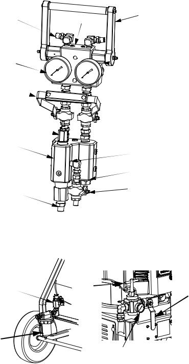
FIG. 1: XP70 Sprayer with optional accessories
Key:
AAir Motor Supply Hose
BMain Air Controls; see page 13
CAir Inlet - 3/4 Npsm(F)
DHigh Pressure Fluid Pump
EAir Motor
FFluid Heater (optional)
GSolvent Flush Pump (optional); see page 14
HSolvent Flush Pump Air Controls; see page 14
J7 Gallon Hoppers (optional)
KCart
LBrake
MHandle (lift to release)
N Fluid Control Assembly; see page 13
P Tie Rods
RMotor Adapter Plate
SAdjustable Packing Nuts with Wet Cups
TYoke With Rod Bearings
URecirculation Lines
VYoke Position Nut
WStatic Mixer Tubes with Replacement Plastic Elements
XMotor Position Indicator
YOver Pressure Rupture Disc; only 38cc, 48cc, and 58cc pumps
12 |
3A0420H |
Component Identification
Fluid Control Assembly
AH |
AA |
AC |
|
|
AF |
AM |
|
|
AE |
|
AJ 
AB
 AL
AL
 AK
AK
 AD
AD
AN
r_571101_3a0420a_3a-2
FIG. 2
Key:
AA Fluid Manifold
AB Mix Manifold
AC Circulation Handle
AD Solvent Flush Valve
AE Dual Shutoff Handle AF Fluid Pressure Gauges
AG Fluid Supply Inlet (Behind Fluid Manifold) AH Fluid Circulation Fittings
AJ B Component Adjustable Fluid Restrictor AK A and B Mix Manifold Check Valves
AL Solvent Inlet Check Valve
AM Automatic Over-Pressure Relief Valves; with grease fittings
AN A and B Combined Outlet; 3/8 npt(m)
Main Air Controls
CE |
CB |
CA |
|
|
|
||
|
|
|
|
|
|
Key: |
|
|
|
CA |
Main Air Motor Shutoff Valve (Relieving) |
|
|
CB |
Main Motor Pressure Regulator |
CC |
|
CC |
Air Filter with Auto Drain |
|
CD Main Pump Air Regulator Gauge |
||
|
CD |
||
|
CE |
Filtered Air Distribution Manifold |
|
FIG. 3
3A0420H |
13 |
Component Identification
45:1 Solvent Flush Pump Kit 262393 (optional)
BA
FIG. 4: Solvent Flush Pump Kit

 BD
BD
 BF
BF
 BE
BE
 BG
BG
Key:
BA Solvent flush pump (Merkur Pump) BB Fluid Inlet
BD Muffler
BE Prime/Flush/Sample valve BF Fluid Outlet Hose
BG Circulation hose
 BB (suction hose not shown)
r_571100_3a0420a_4a-2
Air Controls
Included with optional solvent flush pump kit 262393.
DC 
DE
DB

 DA
DA
DD
Key:
DA Solvent Pump Air Shutoff Valve (Relieving)
DB Solvent Pump Air Regulator
DC Solvent Pump Air Regulator Gauge
DD Air Outlet
DE Air Inlet
r_571101_3a0420a_5a-2
FIG. 5: Solvent Flush Pump Kit Air Controls
14 |
3A0420H |
Component Identification
Air Line
Bleed-type master air valve (CA): required in your system to relieve air trapped between it and the air motor when the valve is closed.
Trapped air can cause the pump to cycle unexpectedly, which could result in serious injury from splashing or moving parts.
•Be sure the valve is easily accessible from the pump and located downstream from the air regulator.
•Pump air regulator (CB): to control pump speed and outlet pressure.
•Air line filter (C): 40 micron filter that removes harmful dirt and moisture from compressed air supply. Accumulated water is automatically drained from the filter.
Fluid Line Accessories
•Fluid Manifold (AA): mounts fluid gauges and over pressure relief valves. Controls circulation and pump priming.
•Mix Manifold (AB): brings A and B fluid together. Provides control and check valves for A, B, and flush fluids.
•Circulation Handle (AC): open to relieve fluid pressure, prime pumps, and circulate material in hoppers. Close to spray mixed material.
•Dual Shutoff Handle (AE): Controls A and B on/off flow into mix manifold. Press down to provide A and B fluid to the mix manifold and into the static mixer for spraying. Press up to turn off A and B before flushing the mixed material.
•Solvent Flush Valve (AD): to flush solvent through mix manifold, hose, and spray gun.
•Static mixer/gun hose kit: to mix the two fluids and deliver mix to the spray gun. Includes static mixer and hoses to the spray gun.
Optional Accessories
•Optional Fluid Heaters (N): to heat the resin and hardener before mixing. Improves the chemical reaction and lowers viscosity to improve the spray pattern.
•Optional Solvent Flush Kit (G): to flush the mix manifold. Includes a solvent pump, mounting hardware, and solvent supply hose.
Flush Before Using Equipment
The equipment was tested with lightweight oil, which is left in the fluid passages to protect parts. To avoid contaminating your fluid with oil, flush the equipment with a compatible solvent before using the equipment. See
Empty and Flush Entire System (new sprayer or end of job), page 27.
3A0420H |
15 |
Setup
Setup
Location
XP70 sprayers are approved for use in hazardous locations only if the base model, all accessories, all kits, and all wiring meet local, state, and national codes.
1.Locate the proportioner on a level surface.
2.Position the proportioner for convenient operator access and maintenance, safe routing of air and fluid lines, and easy connection of components and accessories.
3.For permanent mounting, remove wheels and mount the frame to the floor. See Dimensions, page 54.
4.Ensure that the cart brake (L) is in the locked position.
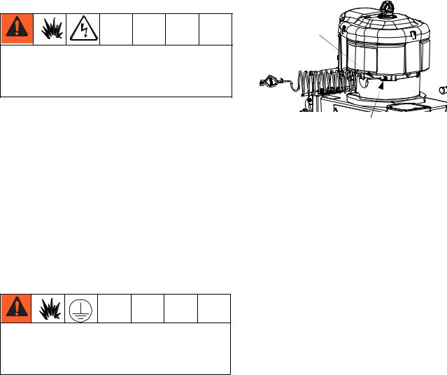
Grounding
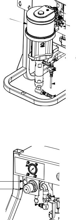
The equipment must be grounded. Grounding reduces the risk of static and electric shock by providing an escape wire for the electrical current due to static build up.
Pump: use ground wire and clamp (supplied). Loosen grounding lug locknut (W) and washer (X). Insert ground wire end (Y) into lug (Z) slot and tighten locknut securely. Connect ground clamp to a true earth ground.
Y
W, X, Z
Solvent Pump: use ground wire and clamp (supplied with solvent pump). Follow instructions in pump manual.
Air and fluid hoses: use only static dissipation type hoses. with a maximum of 500 ft. (150 m) combined hose length to ensure grounding continuity. Check electrical resistance of hoses. If total resistance to ground exceeds 29 megohms, replace hose immediately.
Air compressor: follow manufacturer’s recommendations.
Spray gun: ground through connection to a properly grounded fluid hose and pump.
Fluid supply container: follow local code.
Object being sprayed: follow local code.
Solvent pails used when flushing: follow local code. Use only conductive metal pails, placed on a grounded surface. Do not place the pail on a nonconductive surface, such as paper or cardboard, which interrupts grounding continuity.
To maintain grounding continuity when flushing or relieving pressure: hold metal part of the spray gun firmly to the side of a grounded metal pail, then trigger the gun.
16 |
3A0420H |
Setup
Wire Sprayers with
Explosion-Proof Heaters
(Hazardous location sprayers only)
If your sprayer is rated for hazardous areas, and you have explosion-proof heaters, you must have a qualified electrician connect heater wiring. Ensure wiring and installation comply with local electrical codes for hazardous areas.
Improperly installed or connected equipment will create a hazardous condition and cause fire, explosion, or electric shock. Follow local regulations.
When explosion-proof heaters are used, ensure the wiring, wiring connections, switches, and electrical distribution panel all meet flame-proof (explosion-proof) requirements.
Refer to the Viscon HP heater manual for electrical connection instructions and guidelines in hazardous locations.
3A0420H |
17 |
Loading...