


General ARG45A, ARG45ALB3, AOG45ACA3L, ARG45R, ARG45RLB3 User Manual
...OPERATING MANUAL
BEDIENUNGSANLEITUNG
MODE D’EMPLOI
MANUAL DE FUNCIONAMIENTO
MANUALE DI ISTRUZIONI
ΕΓ ΕΙΡΙ∆Ι ΛΕΙΤ ΥΡΓΙΑΣ
OPERATING MANUAL
РУКОВОДСТВО ПО ЭКСПЛУАТАЦИИ
AIR CONDITIONER
MANUAL DE INSTRUÇÕES
DUCT TYPE
Indoor Unit
ARG25AL
ARG25RL
ARG30AL
ARG30RL
ARG36AL(3)
ARG36RL(3)
ARG45AL(3)
ARG45RL(3)
Outdoor Unit
AOG25AZ
AOG25RZ
AOG30AB
AOG30RB
AOG36AC(3)
AOG36RC(3)
AOG45AC(3)
AOG45RC(3)
KEEP THIS OPERATION MANUAL
FOR FUTURE REFERENCE
 EλληvIkά Italiano Español Français Deutsch English
Русский
FUJITSU GENERAL LIMITED
P/N9362070010-02
Português

CONTENTS
SAFETY PRECAUTIONS .......................................... |
1 |
NAME OF PARTS ...................................................... |
2 |
PREPARATION .......................................................... |
3 |
OPERATION .............................................................. |
3 |
TIMER OPERATION .................................................. |
5 |
ENERGY SAVE OPERATION .................................... |
6 |
CARE AND MAINTENANCE .................................... |
7 |
ERRORS AND SELF DIAGNOSIS ............................ |
7 |
OPERATING TIPS...................................................... |
8 |
SYSTEM OPERATION .............................................. |
9 |
TROUBLESHOOTING ............................................. |
10 |
SPECIFICATIONS .................................................... |
11 |
SAFETY PRECAUTIONS
●Before using the appliance, read these “PRECAUTIONS” thoroughly and operate in the correct way.
●The instructions in this section all relate to safety; be sure to maintain save operating conditions.
●“DANGER”, “WARNING” and “CAUTION” have the following meanings in these instructions:
DANGER! |
This mark indicates procedures which, if improperly performed, are most likely to |
|
result in the death of or serious injury to the user or service personnel. |
||
|
||
|
|
|
WARNING! |
This mark indicates procedures which, if improperly performed, might lead to the |
|
death or serious injury of the user. |
||
|
|
|
CAUTION! |
This mark indicates procedures which, if improperly performed, might possibly result |
|
in personal harm to the user, or damage to property. |
||
|
||
|
|
DANGER!
CAUTION!
●Do not attempt to install this air conditioner by yourself.
●This unit contains no user-serviceable parts. Always consult authorized service personnel for repairs.
●When moving, consult authorized service personnel for disconnection and installation of the unit.
●Do not become over-exposed to cold air by staying in the direct path of the airflow of the air conditioner for extended periods of time.
●Do not insert fingers or objects into the outlet port or intake grilles.
●Do not start and stop air conditioner operation by turning off the electrical breaker and so on.
●In the event of a malfunction (burning smell, etc.), immediately stop operation, turn off the electrical breaker, and consult authorized service personnel.
●Provide occasional ventilation during use.
● Do not direct air flow at fireplaces or heating apparatus.
●Do not climb on, or place objects on, the air conditioner.
●Do not expose the air conditioner directly to water.
●Do not operate the air conditioner with wet hands.
●Turn off power source when not using the unit for extended periods.
●Always turn off the electrical breaker whenever cleaning the air conditioner or changing the air filter.
●Connection valves become hot during Heating; handle with care.
●Check the condition of the installation stand for damage.
●Do not place animals or plants in the direct path of the air flow.
●When restarting after a long period of disuse in the winter, do: Turn the power switch on at least 12 hours before starting the unit.
●Do not drink the water drained from the air conditioner.
●Do not use in applications involving the storage of foods, plants or animals, precision equipment, or art works.
●Do not apply any heavy pressure to radiator fins.
●Operate only with air filters installed.
●Do not block or cover the intake grille and outlet port.
●Ensure that any electronic equipment is at least one metre away from either the indoor or outdoor units.
●Avoid installing the air conditioner near a fireplace or other heating apparatus.
●When installing the indoor and outdoor unit, take precautions to prevent access to infants.
●Do not use inflammable gases near the air conditioner.
En-1

NAME OF PARTS
Instructions relating to heating(*) are applicable only to “HEAT & COOL MODEL” (Reverse Cycle).
Fig. 1 |
|
Fig. 3 |
|
• Square Flange |
• Round Flange |
|
|
|
Electrical Breaker |
||
1 |
1 |
|
|
|
|
|
|
|
|
|
2 |
|
2 |
|
|
||
|
|
3 |
|
|
|
This breaker is installed during |
|
|
|
|
|
|
|
|
|
|
3 |
the electrical installation. |
||
Fig. 2
4
4 
5
Fig. 4 |
H |
I |
J |
K |
D E F |
|
NON STOP CLOCK |
|
TEMP. |
° |
FAN AUTO |
HEAT |
|
OFF ON |
OFF |
|
FAN HIGH |
|||
|
|
|
FAN * |
|||
|
ON |
|
|
|
||
TIMER |
|
|
|
FAN MED |
||
TIMER |
|
|
|
FAN LOW |
COOL |
|
PROGRAM |
ON |
|
|
|||
|
|
|
|
|||
REPEAT |
OFF |
|
|
|
DEFROST |
TEST |
C |
TIMER |
SET |
SET |
FAN |
MASTER |
|
MODE |
||||
|
TIME |
TEMP. |
CONTROL |
CONTROL |
|
|
|
||||
|
CLOCK ADJUST |
|
|
|
|
|
|
ENERGY |
ZONE |
|
START |
|
|
SAVE |
CONTROL |
|
STOP |
|
|
|
|
|
|
|
|
|
|
|
|
|
|
|
|
|
|
|
|
NON STOP CLOCK |
|
TEMP. |
° |
FAN AUTO |
|
|
|||
OFF ON |
OFF |
|
|
FAN HIGH |
HEAT |
* |
|||
ON |
|
|
|
|
|||||
|
|
|
|
|
|
|
|
|
|
TIMER |
TIMER |
FAN MED |
FAN |
|
PROGRAM |
FAN LOW |
COOL |
|
|
ON |
|
|||
|
|
|||
REPEAT |
OFF |
|
DEFROST |
TEST |
|
|
|
|
L Fig. 5 Display |
M N O |
•For explanatory purposes, the figure showing the remote controller display shows all possible displays. The actual display shows only that area that is being adjusted or used.
|
|
B |
A0 98 |
76 G |
|
|
|
|
|
||||
|
|
|
|
|
|
|
|
|
|
|
|
|
|
|
|
|
|
|
|
|
|
|
|
|
|
|
|
|
|
Fig. 1 Indoor Unit |
|
|
|
Fig. 4 Remote Controller |
|
|
|
|
|
|
|
|
|
|
|
|
|
|
H Remote Controller Display |
|
|
|
|||
|
|
|
|
|
|
|
|
|
|
|
|
|
|
|
|
1 Outlet Port |
|
|
6 |
START/STOP Button |
|
|
|
|
|||
|
|
|
|
|
|
|
|
||||||
|
|
2 Intake Port |
|
|
7 |
Operation Lamp |
|
(Fig. 5) |
|
|
|||
|
|
3 Drain Hose |
|
|
8 |
ZONE CONTROL Button |
I Clock Display (CLOCK/TIMER) |
|
|
||||
|
|
|
|
|
9 |
ZONE CONTROL Lamp |
J Set Temperature Display |
|
|
||||
|
|
|
|
||||||||||
|
|
|
|
|
|
: ENERGY SAVE Button |
|
(TEMP.) |
|
|
|||
|
|
Fig. 2 Outdoor Unit |
|
|
|
|
|
|
|||||
|
|
|
|
|
A ENERGY SAVE Lamp |
K Operation Mode Display |
|
|
|||||
|
|
|
|
|
|
|
|
||||||
|
|
4 Intake Port |
|
|
|
|
|
||||||
|
|
|
|
|
B CLOCK ADJUST Button |
L Timer Mode Display |
|
|
|||||
|
|
5 Outlet Port |
|
|
|
C TIMER MODE Button |
M Fan Speed Display |
|
|
||||
|
|
|
|
|
|
D SET TIME Button (▲ / ▼) |
N DEFROST Display |
|
|
||||
|
|
|
|
|
|
|
|
||||||
|
|
|
|
|
|
E SET TEMP. Button (▲ / ▼) |
O TEST Display |
|
|
||||
|
|
|
|
|
|
F FAN CONTROL Button |
|
|
|
|
|
||
|
|
|
|
|
|
|
|
|
|
|
|||
|
|
|
|
|
|
G MASTER CONTROL Button |
|
|
|
|
|
||
|
|
|
|
|
|
|
|
|
|
|
|
|
|
En-2
PREPARATION
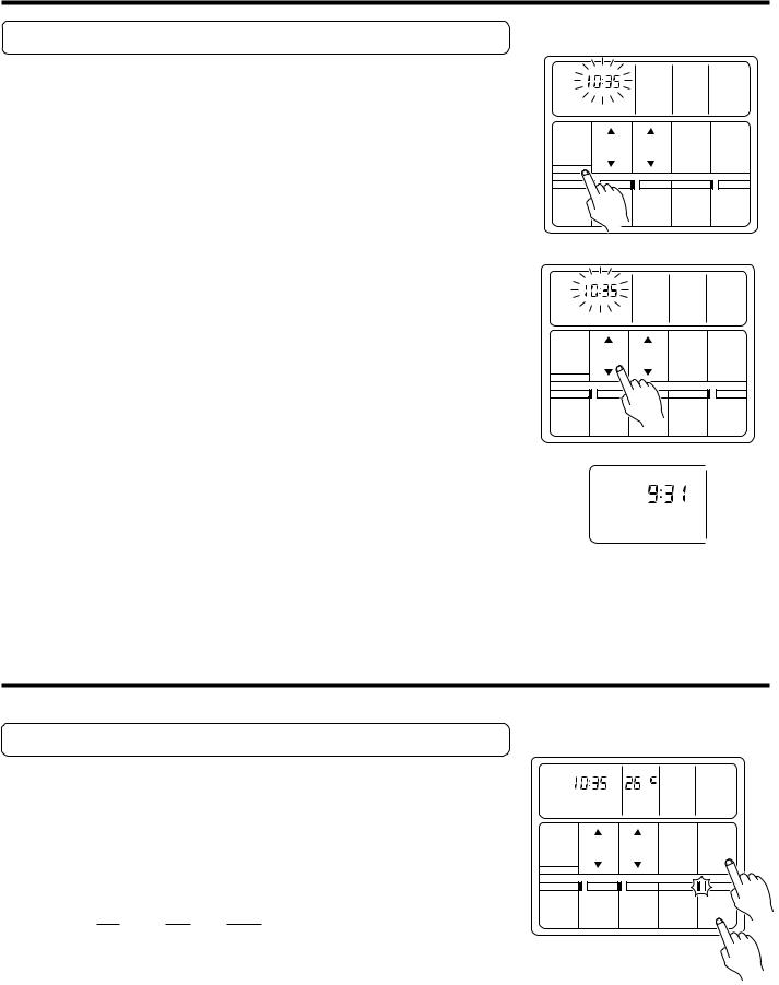
Set the Current Time
1 |
Press the CLOCK ADJUST button for more than three |
seconds. |
The current time display will flash.
NON STOP CLOCK |
TEMP. |
FAN AUTO |
HEAT |
||
OFF ON |
OFF |
° |
FAN HIGH |
||
|
ON |
|
|
FAN |
|
TIMER |
TIMER |
|
FAN MED |
||
PROGRAM |
|
FAN LOW |
COOL |
||
ON |
|
||||
|
|
||||
REPEAT |
OFF |
|
|
DEFROST TEST |
|
|
|
|
|
||
TIMER |
SET |
SET |
FAN |
MASTER |
|
MODE |
|||||
TIME |
TEMP. |
CONTROL |
CONTROL |
||
|
|||||
CLOCK ADJUST |
|
|
|
|
|
|
ENERGY |
ZONE |
|
START |
|
|
SAVE |
CONTROL |
|
STOP |
|
2
3
Press the SET TIME button and set the time.
▲: Use to advance the time forward. ▼: Use to turn the time back.
(Press once to move the time 1 minute; hold down and the time will move 10 minutes at a time.)
The current time display will flash.
Press the CLOCK ADJUST button again.
The current time display will stop flashing.
NON STOP CLOCK |
TEMP. |
FAN AUTO |
HEAT |
||
OFF ON |
OFF |
° |
FAN HIGH |
||
|
ON |
|
|
FAN |
|
TIMER |
TIMER |
|
FAN MED |
||
PROGRAM |
|
FAN LOW |
COOL |
||
ON |
|
||||
|
|
||||
|
|
|
|
||
REPEAT |
OFF |
|
|
DEFROST TEST |
|
|
|
|
|
||
TIMER |
SET |
SET |
FAN |
MASTER |
|
MODE |
|||||
TIME |
TEMP. |
CONTROL |
CONTROL |
||
|
|||||
CLOCK ADJUST |
|
|
|
|
|
|
ENERGY |
ZONE |
|
START |
|
|
SAVE |
CONTROL |
|
STOP |
|
CLOCK
Example: Set the time to 9:31.
OPERATION
Instructions relating to heating (*) are applicable only to “HEAT & COOL MODEL” (Reverse Cycle).
To Select Mode Operation
1
2
Press the START/STOP button.
The unit will start and the operation lamp will light up.
Press the MASTER CONTROL button to select the desired mode.
Each time the button is pressed, the mode will change in the following order:
NON STOP CLOCK |
TEMP. |
FAN AUTO |
HEAT |
|
|
OFF ON |
OFF |
° |
FAN HIGH |
|
|
|
ON |
|
|
FAN |
|
TIMER |
TIMER |
|
FAN MED |
|
|
PROGRAM |
|
FAN LOW |
COOL |
|
|
ON |
|
|
|||
|
|
|
|||
|
|
|
|
|
|
REPEAT |
OFF |
|
|
DEFROST TEST |
|
|
|
|
|
|
|
TIMER |
SET |
SET |
FAN |
MASTER |
|
MODE |
|
||||
TIME |
TEMP. |
CONTROL |
CONTROL |
|
|
|
|
||||
CLOCK ADJUST |
|
|
|
|
|
|
ENERGY |
ZONE |
|
START |
2 |
|
SAVE |
CONTROL |
|
STOP |
|
|
s*HEAT |
sFAN |
s COOL |
|
|
|
|||
|
|
|
|
|
1
Example: When set to COOL
En-3
 Loading...