


 Loading...
Thank you, and congratulations on your choice of BOSS DD-20 Digital Delay.
Before using this unit, carefully read the sections entitled: “USING THE UNIT SAFELY” and “IMPORTANT NOTES” (separate sheet).
These sections provide important information concerning the proper operation of the unit. Additionally, in order to feel assured that you have gained a good grasp of every feature provided by your new unit, this manual should be read in its entirety. The manual should be saved and kept on hand as a convenient reference.
Main Features
●A full 23-second long delay provides plenty of time for loop play and sound-on-sound.
●The Memory function allows you to store up to four tones in the DD-20 itself, independent of the panel settings. You also get “seamless switching,” with memories switched smoothly as the reverberation continues.
●Features a Delay mode with a total of eleven effects, including new “SMOOTH,” “TWIST” and some effects modeled on analog and tape echo effects.
●The new “Time Advance function” provides quick, yet sensitive control of delay times.
●Equipped with custom backlit LCD for clear, easy viewing of delay times, even on dark stages.
Copyright © 2003 BOSS CORPORATION
All rights reserved. No part of this publication may be reproduced in any form without the written permission of BOSS CORPORATION.

Contents |
|
Main Features................................... |
1 |
Installing Batteries................ |
3 |
Making the Connections ...... |
4 |
Mono Connection.................................... |
5 |
Stereo Connection ................................... |
5 |
Connecting the Stereo Output and the |
|
Effects Processor...................................... |
6 |
Connecting to SEND/RETURN ........... |
6 |
With Guitar and Bass Amps........... |
6 |
Connecting to an MTR or Mixer.... |
7 |
Operation ............................... |
8 |
ON/OFF Pedal Operation..................... |
8 |
Panel Operation....................................... |
9 |
Storing Settings (Write Operation)..... |
10 |
Storing the “MANUAL” Sound in |
|
Memory ........................................... |
10 |
Changing and Storing the |
|
“MEMORY” Sound ....................... |
12 |
MEMORY/TAP Pedal Operation |
|
(Switching Memories) .......................... |
14 |
MEMORY/TAP Pedal Operation |
|
(Tap Input) ............................................. |
15 |
Part Names and Functions 16 |
|
Front Panel............................................. |
16 |
Operating the DELAY TIME Knob .. |
17 |
MODE List ...................................... |
18 |
Rear Panel .............................................. |
20 |
How to Use Each Mode....... |
21 |
How to Use SOS (Sound On Sound)... |
21 |
How to Use TWIST................................ |
22 |
How to Use WARP................................ |
22 |
How to Use TAPE.................................. |
23 |
How to Use DUAL ................................ |
24 |
How to Use MODULATE..................... |
25 |
How to Use the Tempo |
|
Function ............................... |
26 |
Indicating the BPM in the |
|
Delay Time Display ............. |
27 |
Settings Made When the |
|
Power is Switched ON ........ |
28 |
Global Procedures .......................... |
28 |
Changing the Pedal Mode Settings..... |
29 |
Setting the Output Mode ...................... |
30 |
Setting the External Pedal Function.... |
31 |
Changing How Memory Numbers Are |
|
Indicated ................................................. |
33 |
Returning Settings to Their Factory |
|
Defaults ................................................... |
34 |
Troubleshooting.................. |
35 |
Sample Settings .................. |
37 |
Setting Memo....................... |
40 |
Specifications...................... |
41 |
Index..................................... |
42 |
2
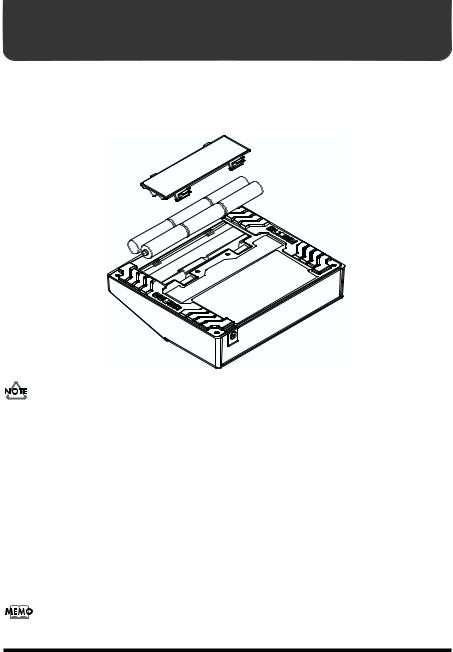
Installing Batteries
Batteries are supplied with the unit. The life of these batteries may be limited, however, since their primary purpose was to enable testing.
Insert the included batteries as shown in figure, being careful to orient the batteries correctly.
fig.02
•When turning the unit upside-down, get a bunch of newspapers or magazines, and place them under the four corners or at both ends to prevent damage to the buttons and controls. Also, you should try to orient the unit so no buttons or controls get damaged.
•When turning the unit upside-down, handle with care to avoid dropping it, or allowing it to fall or tip over.
•Make sure the “+” and “–” ends of the batteries are oriented correctly.
•When the batteries run down, the POWER indicator gets dim. If this happens, replace with new batteries.
•When replacing the batteries, use six AA type.
•Avoid using new batteries together with used ones. In addition, avoid mixing different types of batteries. Doing so can result in fluid leakage.
•Battery life can vary depending on battery type.
Continuous usage time under battery power is about 7 hours with alkaline batteries and about 2 hours with carbon batteries. (This may vary according to usage conditions.)
3

Making the Connections
•The use of an AC adaptor is recommended as the unit’s power consumption is relatively high. Should you prefer to use batteries, please use the alkaline type.
•Noise may be produced if wireless communications devices, such as cell phones, are operated in the vicinity of this unit. Such noise could occur when receiving or initiating a call, or while conversing. Should you experience such problems, you should relocate such wireless devices so they are at a greater distance from this unit, or switch them off.
•Use a cable from Roland to make the connection. If using some other make of connection cable, please note the following precautions.
•Some connection cables contain resistors. Do not use cables that incorporate resistors for connecting to this unit. The use of such cables can cause the sound level to be extremely low, or impossible to hear. For information on cable specifications, contact the manufacturer of the cable.
•When the unit is running on battery power, the power comes on when you insert the connector plug into the INPUT A (MONO) jack.
•To prevent malfunction and/or damage to speakers or other devices, always turn down the volume, and turn off the power on all devices before making any connections.
•If there are batteries in the unit while an AC adaptor is being used, normal operation will continue should the line voltage be interrupted (power blackout or power cord disconnection).
•Once the connections have been completed, turn on power to your various devices in the order specified. By turning on devices in the wrong order, you risk causing malfunction and/or damage to speakers and other devices.
When powering up: |
Turn on the power to your guitar amp last. |
When powering down: |
Turn off the power to your guitar amp first. |
•Always make sure to have the volume level turned down before switching on power. Even with the volume all the way down, you may still hear some sound when the power is switched on, but this is normal, and does not indicate a malfunction.
•When operating on battery power only, the unit’s indicator and backlit LCD will become dim when battery power gets too low. Replace the battery as soon as possible.
•When moved from one location to another where the temperature and/or humidity is very different, water droplets (condensation) may form inside the unit. Damage or malfunction may result if you attempt to use the unit in this condition. Therefore, before using the unit, you must allow it to stand for several hours, until the condensation has completely evaporated.
4

Making the Connections
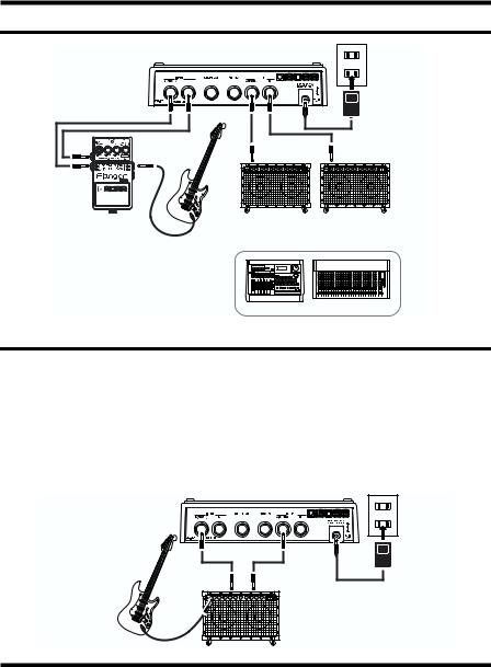
Mono Connection
fig.03
AC Adaptor PSA-series (option)
Electric Guitar |
or |
or |
(Electric Bass) |
|
MTR |
|
|
|
|
Bass Amplifier |
Guitar Amplifier |
Mixer
Stereo Connection
fig.04
AC Adaptor PSA-series (option)
Electric Guitar |
or |
|
(Electric Bass) |
||
MTR |
||
|
Guitar Amplifier
(Bass Amplifier)
Mixer
5
Making the Connections
Connecting the Stereo Output and the Effects Processor
fig.05
AC Adaptor PSA-series (option)
Effector |
Guitar Amplifier |
||
(Bass Amplifier) |
|||
|
|||
Electric Guitar |
or |
|
|
(Electric Bass) |
|
|
|
|
MTR |
Mixer |
|
Connecting to SEND/RETURN
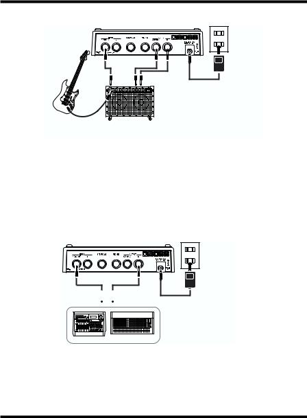
With Guitar and Bass Amps
*Match the DD-20's level setting and the output level from the guitar or bass amp's SEND output. If there is any distortion in the sound, reduce the level on the connected device.
*If the guitar or bass amp's SEND/RETURN level is +4 dBu, switch the setting to “+4 dB” as described in “Setting the Output Mode” (p. 30).
Mono Send/Mono Return
fig.06
SEND |
RETURN |
Electric Guitar |
Guitar Amplifier |
(Electric Bass) |
(Bass Amplifier) |
AC Adaptor PSA-series (option)
6
Making the Connections
Mono Send/Stereo Return
fig.06a
AC Adaptor PSA-series (option)
SEND RETURN R |
RETURN L |
Electric Guitar |
Guitar Amplifier |
(Electric Bass) |
(Bass Amplifier) |
Connecting to an MTR or Mixer
Mono Send/Mono Return
When using the DD-20 while connected to the SEND/RETURN of a mixer or multitrack recorder, follow the instructions in “Setting the Output Mode” (p. 30) to set “A: Direct Sound + B: Effect Sound” so that only the delay signal is output from the DD-20; the sound is output from the OUTPUT B jack.
fig.07a
AC Adaptor
PSA-series
(option)
SEND 
 RETURN
MTR Mixer
7
Operation
“Effect On” for the pedal setting and “MANUAL” is selected when the power is turned on.
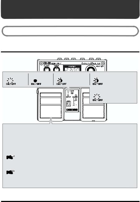
ON/OFF Pedal Operation
fig.12
When at “ON”


 ← Lit
← Lit
When at “OFF” When at “WARP” or “TWIST” When at “SOS” REC or OVERDUB |
|||||
← |
Not lit |
← |
Blink |
← |
Blink |
When at “SOS” PLAY


 ← Lit
← Lit
Each press of the ON/OFF pedal switches effects on or off. When effects are off, the sound coming in through the INPUT jack is output unchanged.
*If the output is set to “A:DIR B:EFX,” nothing is output from the OUTPUT B jack when the effects are off.
Only the effect sound is output from the OUTPUT B jack when the effects are on. This is set at the factory to “A:DIR B:EFX.”

 “Setting the Output Mode” (p. 30)
*The pedal functions differently according to the Pedal mode settings.

 “How to Use Each Mode” (p. 21)
*The DD-20 features a “seamless switching function” whereby the reverberation sound decays gradually, even after the effects are switched off.
8
Operation
Panel Operation
In order to follow along with the instructions given here, you should start out by having effects switched ON (press the ON/OFF pedal and confirm that the ON/ OFF indicator has lighted), and press the SELECT button to switch MANUAL (MANUAL indicator has lighted in green).
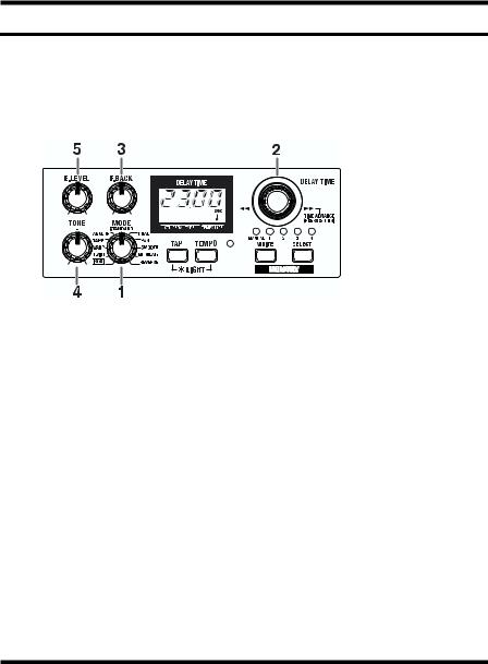
Also set the knobs as shown in the illustration.
fig.17
1.Rotate the MODE knob to select an appropriate delay effect from the eleven available types.
2.Adjust the delay time by rotating the DELAY TIME knob.
*Pressing the knob down as you turn it cause the delay time to change more rapidly. Furthermore, the rate at which it changes also varies according to how the knob is turned. More detail, refer to “Operating the DELAY TIME Knob” (p. 17).
3.Rotate the F. BACK knob to adjust the amount of the feedback.
4.Adjust the tone of the effect sound with the TONE knobs.
The frequency response is flat when the knob is at the center position. You can usually leave the knob at the center position.
5.Adjust the volume of the effect sound with the E.LEVEL knob.
Saving the Current Delay Time as the “Manual” Setting
If you press the DELAY TIME knob after adjusting the delay time, the current delay time is then stored to the DD-20 as the “Manual” setting.
This setting is preserved even while the power is turned off, and is selected as
the default delay time setting (display) when the power is turned on again.
9
Operation
Storing Settings (Write Operation)
Storing the “MANUAL” Sound in Memory
Do not switch off the power while a write operation is in progress.
* You cannot carry out the Write operation when the MODE knob is turned to “SOS.”
1.Create the sound you want using knobs.
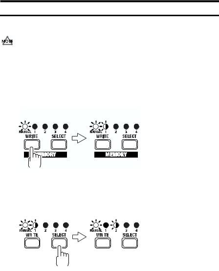
2.Press the WRITE button.
The MEMORY indicator and the indicator for the currently selected memory flash,
and the DD-20 is put into write standby.
fig.19a
Write standby
Blink
3.Press the SELECT button to select the memory (number) to which you want to store the sound.
The indicator for the selected memory number flashes.
fig.19b
|
|
|
|
|
|
|
|
|
|
|
|
|
|
|
|
|
Write standby |
|
|
||
|
|
Blink |
|
Blink |
|
|
||||
|
|
|
|
|
|
|
|
|
|
|
|
|
|
|
|
|
|
|
|
|
|
|
|
|
|
|
|
|
|
|
|
|
|
|
|
|
|
|
|
|
|
|
|
|
|
|
|
|
|
|
|
|
|
|
|
|
|
|
|
|
|
|
|
|
|
|
|
|
|
|
|
|
|
|
|
|
|
|
|
|
|
|
|
|
|
|
|
10
Operation
4.Press the WRITE button.
The write operation is completed when the indicator for the write-destination
memory begin to flash more rapidly.
fig.20
|
|
|
|
|
|
|
|
|
|
|
|
|
|
|
|
|
|
Writing |
|
Write Finished |
|
||
|
|
|
Blink |
Blink rapidly |
|
|
|
|
|
||
|
|
|
|
|
|
|
|
|
|
|
|
|
|
|
|
|
|
|
|
|
|
|
|
|
|
|
|
|
|
|
|
|
|
|
|
|
|
|
|
|
|
|
|
|
|
|
|
|
|
|
|
|
|
|
|
|
|
|
|
|
|
|
|
|
|
|
|
|
|
|
|
|
|
|
|
|
|
|
|
|
|
|
|
*To cancel the write operation, then before you press the WRITE button, rotate the knob or operate the MANUAL/TAP pedal.
Please be aware that all data contained in the unit’s memory may be lost when the unit is sent for repairs. Important data should always be written down on paper, “Setting Memo” (p. 40). During repairs, due care is taken to avoid the loss of data. However, in certain cases (such as when circuitry related to memory itself is out of order), we regret that it may not be possible to restore the data, and Roland assumes no liability concerning such loss of data.
Please be aware that the contents of memory can be irretrievably lost as a result of a malfunction, or the improper operation of the unit. To protect yourself against the risk of loosing important data, we recommend that you write down important data you have stored in the unit’s memory on “Setting Memo” (p. 40).
Unfortunately, it may be impossible to restore the contents of data that was stored in the unit’s memory once it has been lost. Roland Corporation assumes no liability concerning such loss of data.
11
Operation
Changing and Storing the “MEMORY” Sound
Do not switch off the power while a write operation is in progress.
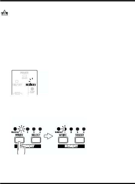
1.Press the MANUAL/TAP pedal or the SELECT button to change to the “MEMORY” sound.
2.Operate the knobs to change the sound.
*To avoid sudden inadvertent changes in sound, the E.LEVEL, TONE, and F. BACK knobs are designed so that the setting does not change unless the knob is first turned as far as the stored setting value. Once the position of the knob matches the setting value stored in memory, the sound starts to change.
When a setting changes, the MEMORY indicator flashes automatically.
fig.21
 Blink
Blink
3.Press the WRITE button.
The MEMORY indicator and the indicator for the currently selected memory
number start to flash, and the DD-20 is put into write standby.
fig.22
Write standby
Blink
12
Operation
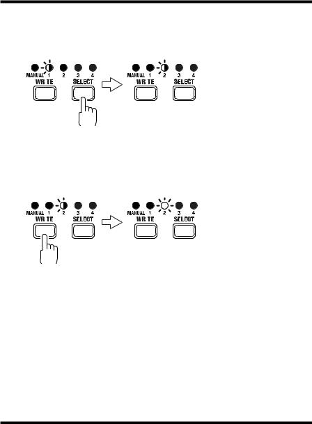
4.Press the SELECT button to select the memory (number) to which you want to store the sound.
The indicator for the selected memory number flashes.
fig.22a
|
|
|
|
|
|
|
|
|
|
|
|
Blink |
Blink |
|
|||||
|
|
|
|
|
|
|
|
|
|
|
|
|
|
|
|
|
|
|
|
|
|
|
|
|
|
|
|
|
|
|
|
|
|
|
|
|
|
|
|
|
|
|
|
|
|
|
|
|
|
|
|
|
|
|
|
|
|
|
|
|
|
|
|
|
|
|
|
|
|
5.Press the WRITE button.
The write operation is completed when the indicator for the write-destination
memory begin to flash more rapidly.
fig.23
|
|
|
|
|
|
|
|
|
|
|
|
Blink rapidly |
Lit |
|
|||
|
|
|
|
|
|
|
|
|
|
|
|
|
|
|
|
|
|
|
|
|
|
|
|
|
|
|
|
|
|
|
|
|
|
|
|
|
|
|
|
|
|
|
|
|
|
|
|
|
|
|
|
|
|
|
|
|
|
|
|
|
|
|
*If the knob or the MANUAL/TAP pedal position is changed before the WRITE button is pressed, the write operation is cancelled, and the DD-20 is returned to the status in effect in Step 2.
13
Operation
MEMORY/TAP Pedal Operation
(Switching Memories)
The Pedal mode (1–3) changes the function of the pedals. Use the most appropriate
setting for your particular application.
*The following operations are performed while the MEMORY indicator is lit.
*The DD-20 features a “seamless switching function.”
When you switch memories using this function, the reverberation from the memory prior to switching continues to sound, for more natural-sounding transitions.
*At the factory settings, Pedal mode is set to “1.”
When changing the Pedal mode settings, refer to p. “Changing the Pedal Mode Settings” (p. 29).
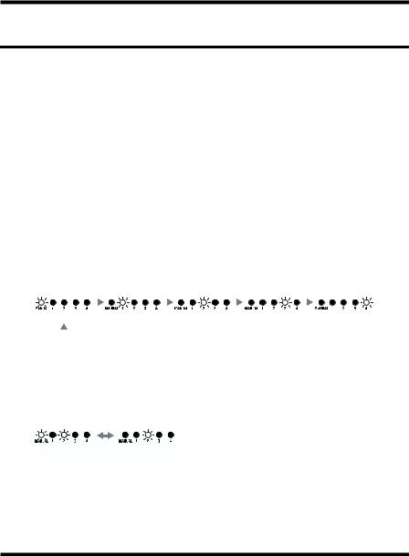
Pedal mode: 1
Pressing the MEMORY/TAP pedal cycles you through a series of selections, in this order: MANUAL → MEMORY 1 → MEMORY 2 → MEMORY 3 → MEMORY 4 → MANUAL. This convenient feature makes it easier to switch memories in which multiple memories are used.
fig.9
|
|
|
|
|
|
|
|
|
|
|
|
|
|
|
|
|
|
|
|
|
|
|
|
|
|
|
MANUAL |
|
MEMORY 1 |
|
MEMORY 2 |
|
MEMORY 3 |
|
MEMORY 4 |
|
|
|
|
|
|
|
|
|
|
|
|
|
|
|
|
|
|
|
|
|
|
|
|
|
|
|
|
|
|
|
|
|
|
|
|
|
|
|
|
|
|
Pedal mode: 2
Pressing the MEMORY/TAP pedal switches you between MANUAL and the selected memory (shown by the lit indicator). This is a convenient way to toggle between two sound settings.
fig.10
MANUAL MEMORY
14
Loading...