


 Owner’s Manual
Main features
The ES-8 is a switching system that lets you connect effect pedals and other effect units, and then store and recall up to 800 different combinations of them.
55 It provides dedicated jacks for connecting stereo-in/out effect units and volume pedals.
55 It also provides a wide variety of external control functions for controlling your amp and effects in real time.
Contents
Panel Descriptions. . . . . . . . . . . . . . . . . . . . . . . . . . . . . . . . . . . . . . . . . |
2 |
Rear Panel (Connecting Your Equipment). . . . . . . . . . . . . . . . . . . . |
2 |
Top Panel.. . . . . . . . . . . . . . . . . . . . . . . . . . . . . . . . . . . . . . . . . . . . . . . |
4 |
Attaching the Rubber Feet.. . . . . . . . . . . . . . . . . . . . . . . . . . . . . . . . |
5 |
Installing the ES-8 in a Pedalboard. . . . . . . . . . . . . . . . . . . . . . . . . . |
5 |
Turning the Power On and Off . . . . . . . . . . . . . . . . . . . . . . . . . . . . . |
5 |
Switching the Play Screen . . . . . . . . . . . . . . . . . . . . . . . . . . . . . . . . . |
5 |
Saving/Recalling a Combination of Effect Units |
|
(Memory Mode) . . . . . . . . . . . . . . . . . . . . . . . . . . . . . . . . . . . . . . . . . . . |
6 |
Patch Structure.. . . . . . . . . . . . . . . . . . . . . . . . . . . . . . . . . . . . . . . . . . |
6 |
Switching Between Memory and Manual Modes . . . . . . . . . . . . . |
6 |
Saving a Patch (Patch Write) . . . . . . . . . . . . . . . . . . . . . . . . . . . . . . . |
6 |
Recalling a Patch (Patch Change). . . . . . . . . . . . . . . . . . . . . . . . . . . |
6 |
Creating a Patch. . . . . . . . . . . . . . . . . . . . . . . . . . . . . . . . . . . . . . . . . . . |
7 |
Block Diagram . . . . . . . . . . . . . . . . . . . . . . . . . . . . . . . . . . . . . . . . . . . |
7 |
Tips for Creating Patches (Sounds). . . . . . . . . . . . . . . . . . . . . . . . . . |
7 |
Changing the Effect Loop Settings. . . . . . . . . . . . . . . . . . . . . . . . . . |
8 |
Changing the Effect Loop Connection Order. . . . . . . . . . . |
8 |
Making a Parallel Connection. . . . . . . . . . . . . . . . . . . . . . . . . |
8 |
Specifying Carry Over.. . . . . . . . . . . . . . . . . . . . . . . . . . . . . . . |
8 |
Editing the Settings of a Patch (Memory Edit Mode) . . . . . . . . . . |
9 |
Quick Edit. . . . . . . . . . . . . . . . . . . . . . . . . . . . . . . . . . . . . . . . . . |
9 |
Basic Operation. . . . . . . . . . . . . . . . . . . . . . . . . . . . . . . . . . . . . |
9 |
Parameter List. . . . . . . . . . . . . . . . . . . . . . . . . . . . . . . . . . . . . . |
9 |
Making Global Settings (System Setting). . . . . . . . . . . . . . . . . . |
12 |
List of Parameters . . . . . . . . . . . . . . . . . . . . . . . . . . . . . . . . . . . . . . . . |
12 |
Patch/Data Operations (Utility). . . . . . . . . . . . . . . . . . . . . . . . . . . . 13 Copying a Patch (Patch Copy). . . . . . . . . . . . . . . . . . . . . . . . . . . . . . 13
Exchanging Patches (Patch Exchange). . . . . . . . . . . . . . . . . . . . . . 13
Initializing a Patch (Patch Init). . . . . . . . . . . . . . . . . . . . . . . . . . . . . . 13 Copying a Bank (Bank Copy). . . . . . . . . . . . . . . . . . . . . . . . . . . . . . . 13
Exchanging Banks (Bank Exchange). . . . . . . . . . . . . . . . . . . . . . . . . 13 Transmitting Data to an External MIDI Device (Bulk Dump) . . . . 13 Restoring the Factory Settings (Factory Reset).. . . . . . . . . . . . . . . 13
Advanced Applications. . . . . . . . . . . . . . . . . . . . . . . . . . . . . . . . . . . . 14 Adjusting the Level of Each Patch.. . . . . . . . . . . . . . . . . . . . . . . . . . 14 Switching Between Two Guitars. . . . . . . . . . . . . . . . . . . . . . . . . . . . 14 Switching Between Two Amps . . . . . . . . . . . . . . . . . . . . . . . . . . . . . 15 Switching the Amp’s Channels . . . . . . . . . . . . . . . . . . . . . . . . . . . . . 15
Connecting with the Four-Cable Method / Also Switching the Amp’s Channels. . . . . . . . . . . . . . . . . . . . . . . . . . . . . . . . . . . . . . . . . . 15
Reducing Hum.. . . . . . . . . . . . . . . . . . . . . . . . . . . . . . . . . . . . . 15
Changing the BOSS PH-3’s Rate for Each Patch . . . . . . . . . . . . . . . 16 Using an Expression Pedal to Control the BOSS PH-3’s Rate . . . . 16 Using the [BANK H] Switch to Turn Delay On/Off . . . . . . . . . . . . . 17 Using Number Switch [7] to Change the Delay Time . . . . . . . . . . 17 Using Tap Tempo to Set the Delay Time of Each Patch. . . . . . . . . 18
Applying Chorus Only While the Currently Selected Number Switch Is Held Down. . . . . . . . . . . . . . . . . . . . . . . . . . . . . . . . . . . . . . 18
Using CC (Control Change) to Control a MIDI-Equipped Effect
Unit When the Patch Changes.. . . . . . . . . . . . . . . . . . . . . . . . . . . . . 19
Connecting a Wah or Fuzz (Input Buffer Off) . . . . . . . . . . . . . . . . . 19
Appendix. . . . . . . . . . . . . . . . . . . . . . . . . . . . . . . . . . . . . . . . . . . . . . . . . . 20
Troubleshooting . . . . . . . . . . . . . . . . . . . . . . . . . . . . . . . . . . . . . . . . . 20
Error Messages. . . . . . . . . . . . . . . . . . . . . . . . . . . . . . . . . . . . . . . . . . . 20
Main Specifications. . . . . . . . . . . . . . . . . . . . . . . . . . . . . . . . . . . . . . . 21
USING THE UNIT SAFELY. . . . . . . . . . . . . . . . . . . . . . . . . . . . . . . . . . . |
21 |
IMPORTANT NOTES. . . . . . . . . . . . . . . . . . . . . . . . . . . . . . . . . . . . . . . . |
21 |
Before using this unit, carefully read “USING THE UNIT SAFELY” and “IMPORTANT NOTES” (leaflet “USING THE UNIT SAFELY” and Owner’s Manual (p. 21)). After reading, keep the document(s) including those sections where it will be available for immediate reference.
Copyright © 2015 ROLAND CORPORATION
Panel Descriptions
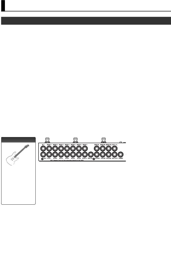
Rear Panel (Connecting Your Equipment)
SEND 1–6, RTN 1–6 jacks
These jacks provide mono-send mono-return effect loops.
Signals are sent from SEND 1–6 jacks to each effect unit, and the signals from each effect unit are received at the RTN 1–6 jacks.
Connect the SEND 1–6 jacks to the INPUT jack of each effect unit, and connect the OUTPUT jack of each effect unit to the RTN 1–6 jacks.
SEND 7, RTN 7L/R jacks
These jacks provide a mono-send stereo-return effect loop.
*If the last stage of the chain is the stereo-send effect loop or the output, the signal is output in stereo. If the last effect loop in the chain is the mono-send effect loop, only the signal received at the RTN 7L jack is output.
*A mono-return effect can also be connected here. Connect it to the RTN 7L jack. In this case, if a stereo-send effect loop or the output is connected later, the signal received at the RTN 7L jack is output.
SEND 8L/R, RTN 8L/R jacks
These jacks provide a stereo-send stereo-return effect loop.
*If the stereo output is connected as the last stage, the output is stereo. If the last effect loop is monosend, only the signal received at the RTN 8L jack is output.
*A mono-send/return effect can also be connected here. Connect it to the SEND 8L/RTN 7L jacks. In this case, if a stereo-return effect loop or the output is connected later, the signal received at the RTN 8L jack is output.
|
MEMO |
|
For the returns of effect loops 7 and 8, set the system setting Preference to select mono- |
|
|
|
return or stereo-return (p. 12). |
RTN |
SEND |
RTN |
RTN |
SEND |
RTN |
RTN |
SEND |
SEND |
|
L |
R |
R |
L |
L |
R |
||||
|
|
|
IN 1, 2 jacks |
TUNER jack |
This jack is for connecting an external tuner.
The signal that is input from the jack selected by Input Sel (p. 9) is output from this jack even if mute is on.
Connect your guitars or basses to these jacks.
The settings determine which input is selected.
It is not possible for both inputs to be selected simultaneously.
NOTE
SEND VOL, RTN VOL jacks |
|
OUT 1/L, 2/R jacks |
|
These jacks are for |
|
|
|
connecting a volume pedal. |
RTN |
SEND |
|
* You can also use these |
|||
|
|
||
jacks as send/return for a |
|
|
|
preamp (p. 15). |
|
|
|
|
|
These are the output jacks. |
|
|
|
OUT 1/L and OUT 2/R can be turned on/off |
|
|
|
independently. |
|
|
|
Pressing the [MUTE] switch mutes the output |
|
|
|
from the OUT 1/L and 2/R jacks. |
To prevent malfunction and equipment failure, always turn down the volume, and turn off all the units before making any connections.
2

Panel Descriptions
EXT CTL jacks
CTL 1/2–5/6 jacks
These are control jacks for latch or momentary operation.
You can use them to control various things such as switching amp channels or turning reverb on/off.
If you’re using an effect device that’s equipped with a footswitch jack, connect that jack here.
Each of these jacks can accommodate a stereo 1/4” plug (TRS) to make the appropriate connection to the device you’re controlling.
*If 1/4” plug cables are connected, only CTL 1, CTL 3, and CTL 5 are available.
TIP |
RING |
CTL 1 |
CTL 2 |
CTL 3 |
CTL 4 |
CTL 5 |
CTL 6 |
EXP 1, 2 jacks
If you’re using an effect unit that allows an expression pedal (such as the Roland EV-5) to be connected, connect it to this jack.
This allows an expression pedal connected to the CTL IN EXP 1, 2 jacks or the values you’ve specified to control the effect unit on the ES-8.
RTN |
SEND |
EXP
CTL IN jacks
These let you control effect units or amps that are connected to the EXT CTL jacks.
To use these as EXP 1, 2 jacks
Connect an expression pedal (such as the Roland
EV-5).
To use these as CTL 1/2, 3/4 jacks
Connect a footswitch.
|
|
FS-5U x 2 |
Mode/Polarity switch |
Stereo 1/4” phone type |
|
FS-5U |
|
. |
|
/ |
|
|
1/4” phone type |
|
FS-6 |
|
|
|
TIP |
RING |
FS-7
CTL 1 |
CTL 2 |
CTL 3 |
CTL 4 |
MIDI connectors
Connect an external MIDI device here to transmit and receive MIDI messages.
The operation of the MIDI OUT/THRU connectors depends on the system settings (p. 12).
MIDI device
DC IN jack
Connect the included AC adaptor here.
The power turns on when you plug the connected AC adaptor into an AC outlet.
NOTE
55 This instrument is equipped with balanced 


 (TRS) type jacks. Wiring diagrams for these


 jacks are shown below. Make connections
 after first checking the wiring diagrams of other equipment you intend to connect.
55 Use only the specified expression pedal (FV-500H, FV-500L, Roland EV-5; sold separately). By connecting any other expression pedals, you risk causing malfunction and/or damage to the unit.
FS-5U |
|
x 1 |
|
|
|
|
|
FS-6 |
FS-7 |
||||
1/4” phone type |
Stereo 1/4” |
phone type |
Stereo 1/4” phone type |
|||
. |
. |
. |
||||
/ |
/ |
/ |
||||
1/4” phone type |
Stereo 1/4” phone type |
Stereo 1/4” phone type |
||||
CTL 2
CTL 4
CTL 1 |
CTL 2 |
CTL 1 |
CTL 1 |
|
|||
CTL 3 |
CTL 4 |
CTL 3 |
CTL 3 |
|
3
Panel Descriptions
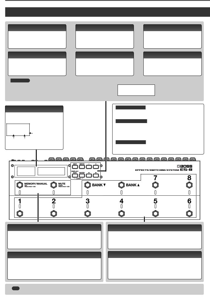
Top Panel
[EDIT] button
Press this to make patch settings or system settings.
[WRITE] button
Press this to save patch settings.
[–] [+] buttons
Use these to edit the value of a setting.
*Hold down one button while pressing the other button to make the value change
[DISPLAY/EXIT] button |
[ENTER] button |
Press this to switch the play screen, to cancel an |
Press this to confirm an operation. |
operation, or to return to the previous screen. |
|
When you press the [DISPLAY/EXIT] button and [ENTER] button simultaneously to activate Lock function, all buttons will be disabled.
This prevents settings from being changed when you inadvertently press a button.
The Lock function turns off when you press the two buttons simultaneously once again.
[K] [J] buttons
Use these to move the cursor or to select a category or parameter.
LOCKED!
Display
The ES-8 shows various information here.
The display at the left shows the bank/number.
008. . Blinks in
synchronization
with the tempo.
Bank Number
*The explanations in this manual include illustrations that depict what should typically be shown by the display. Note, however, that your unit may incorporate a newer, enhanced version of the system (e.g., includes newer sounds), so what you actually see in the display may not always match what appears in the manual.
What is an effect loop?
This is a connection in which an effect device is connected via send and return jacks. The ES-8 provides eight effect loops, 1–8.
What is memory mode?
In this mode, you can select “patches,” where each patch is a combination of effect loops and various settings.
You can select from 800 patches by using the switches to specify the bank and number.
What is manual mode?
In this mode you can turn the effect loops (1–8) on/off individually.
[MEMORY/MANUAL] switch
Switches between memory mode (indicator lit blue) and manual mode (lit red). Hold down the switch for two seconds or longer to enter memory edit mode.
[MUTE] switch
Mutes the sound that is output from the ES-8. If mute is on, the indicator is lit blue.
Hold down the switch for two seconds or longer to enter the bypass state (indicator lit red); the input is output without change.
[BANK I] [BANK H] switches
Use these to switch banks in memory mode.
Number switch [1]–[8]
Use these to select a patch number. The indicator of the currently selected number is lit blue.
In manual mode, these switches turn each effect loop (1–8) on/off individually. When an effect loop is on, its number indicator is lit red.
|
MEMO |
You can also assign a different function to each switch (p. 10). |
4
Panel Descriptions
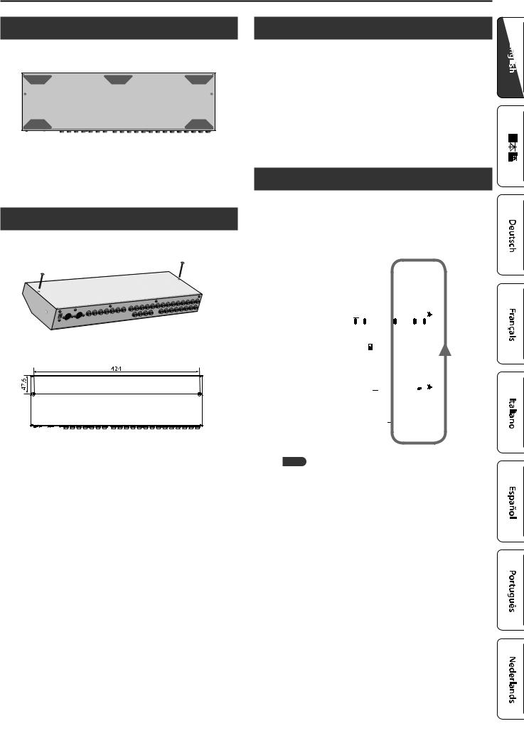
Attaching the Rubber Feet
You can attach the rubber feet (included) if necessary.
Attach them in the locations shown in the illustration.
*When turning the unit over, be careful so as to protect the buttons and switches from damage. Also, handle the unit carefully; do not drop it.
*If the rubber feet are not attached correctly, the unit may be deformed when you press the switches.
Installing the ES-8 in a Pedalboard
You can fasten the ES-8 to your pedalboard by installing the included screws in the screw holes on the bottom of the unit.
*You must use only the included screws. Using other screws may damage the ES-8 or cause malfunctions.
Unit: mm
Turning the Power On and Off
Once everything is properly connected (p. 2), be sure to follow the procedure below to turn on their power. If you turn on equipment in the wrong order, you risk causing malfunction or equipment failure.
When powering up: Turn on the power to your guitar amp last.
When powering down: Turn off the power to your guitar amp first.
*This unit is equipped with a protection circuit. A brief interval (a few seconds) after turning the unit on is required before it will operate normally.
Switching the Play Screen
The screen that appears when you turn on the power is called the “play screen,” and the state in which the play screen is shown is called “play mode.”
There are five types of play screen as shown in the following illustration, and you can use the [DISPLAY/EXIT] button to switch between them.
Patch name screen |
Patch Name |
|
|
|||
Master BPM& |
|
|
|
|
Ì=120 |
|
|
|
|
|
|
|
|
|
|
|
|
|
|
|
Loop On/Off screen |
8 |
7 |
6 |
5 4 3 |
2 |
1 |
|
|
|
|
|
|
|
|
|
|||||
|
|
|
|
|
|
|
Loop Structure screen |
=8=_-6-5-4-3-2-1 |
|||||
|
|
|
|
|
|
|
|
|
|
||||
|
|
|
||||
CTL Out screen |
|
CTL1|CTL2|CTL3 |
||||
|
120| OFF| |
|
3 |
|||
|
|
|
||||
|
|
|
|
|
||
|
|
|
|
|
|
|
EXP Out screen |
EXP1 |
|
|EXP2 |
|
||
|
|
EXP1| |
|
127 |
||
|
|
|
|
|||
|
|
|
|
|
|
|
MEMO
Even in play mode, you can use the [K] [J] buttons and [–] [+] buttons to edit the settings.
To save your edited settings, use the patch write (p. 6) operation.
5
Saving/Recalling a Combination of Effect Units (Memory Mode)
“Memory mode” is the mode in which you can save combinations of effect loops (patches) in the ES-8, and recall those saved settings. In contrast to memory mode, “manual mode” is the mode in which you can use the switches to turn each effect loop on/off manually.
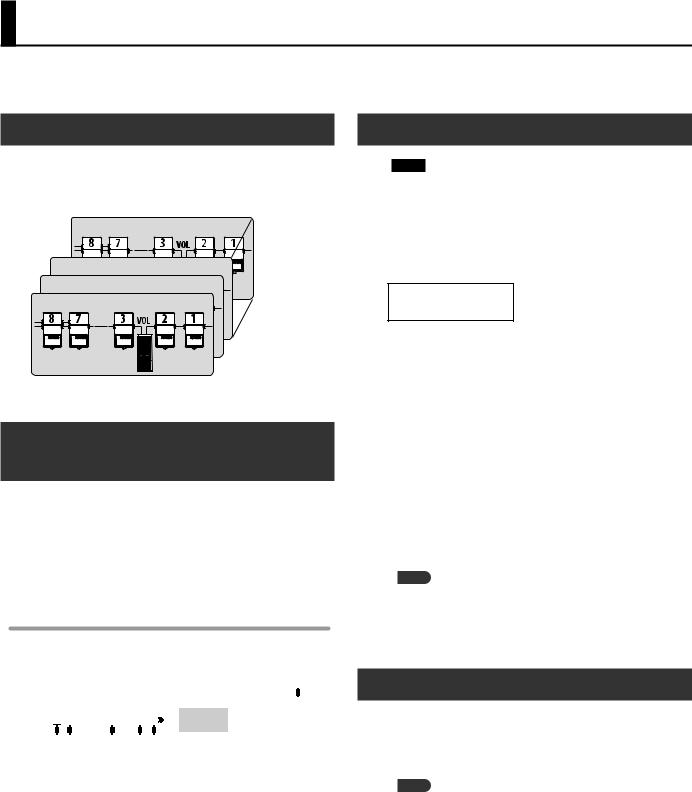
Patch Structure
A “patch” consists of a combination of effect loops (each effect loop’s on/off status and connection order) and parameter settings.
Patches are organized by bank (00–99) and number (1–8). You can store 800 patches.
 Patch 99-8
Patch 00-3
00-3
Patch 
 00-2
00-2
Patch


 00-1
00-1
Switching Between Memory and Manual
Modes
1. Press the [MEMORY/MANUAL] switch.
Each time you press this switch, you alternate between memory mode and manual mode.
55 In memory mode, the MEMORY/MANUAL indicator is lit blue. 55 In manual mode, the MEMORY/MANUAL indicator is lit red.
In manual mode
Pressing the number switches [1]–[8] turns each effect loop on/off.
55 The number indicator is lit red if the corresponding effect loop is on, and unlit if that effect loop is off.
55 If an effect loop is on, the Loop On/Off screen shows an “ ” icon.
8 7 6 |
5 |
4 3 |
2 1 |
|
1, 2, 4, 7, 8 |
On |
|
3, 5, 6 |
Off |
||||
|
|
|
|
|
||
|
|
|
|
|
|
|
Saving a Patch (Patch Write)
NOTE
55 The patch you created is lost if you turn off the power or switch patches before performing the patch write operation.
55 When you perform the patch write operation, the patch that was in the save-destination is lost.
1. Press the [WRITE] button.
00-1
Patch name
2.Use the [K] [J] buttons and [–] [+] buttons to select the save-destination bank number and patch number.
*You can also use the [BANK I] [BANK H] switches and number switches [1]–[8] to select the bank number and patch number.
3.Press the [ENTER] button.
4.Use the [K] [J] buttons and [–] [+] buttons to assign a patch name.
*If you decide to cancel the patch write operation, press the [DISPLAY/EXIT] button several times.
5.Press the [WRITE] button or the [ENTER] button.
The display indicates “Executing...,” and then the previous display reappears when patch write is completed.
MEMO
55 You can write a patch from either memory mode or manual mode.
55 When you write a patch, the ES-8 switches to memory mode.
Recalling a Patch (Patch Change)
1.Use the [BANK I] [BANK H] switches to select a bank.
2.Use the number switches [1]–[8] to select a patch.
MEMO
55 In the patch name screen of Play mode, you can use the [K] [J] buttons to select a patch.
55 You can specify whether the next patch is selected as soon as you use the [BANK I] [BANK H] switches to change banks, or whether the patch is not changed until you then press a number switch.
For details on how to make this setting, refer to “Making Global Settings (System Setting)” (p. 12).
6
Creating a Patch
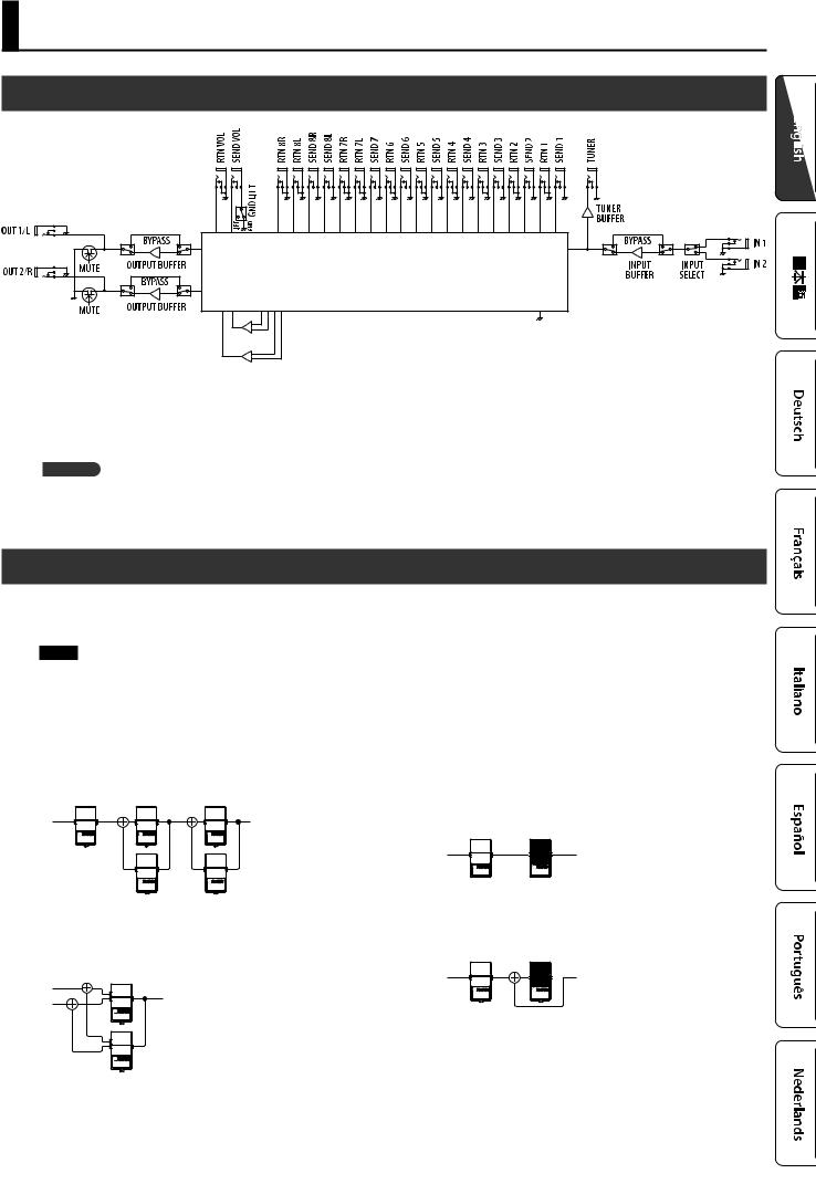
Block Diagram
ANALOG SWITCH ARRAY
MIXER 1 |
MIXER 2
The ES-8 uses an “analog switch array” that lets you freely change the connection order of your effect units.
It also contains two internal mixers, and lets you create a wide range of sounds by connecting effect units in parallel or using the “Carry Over” function.
Carry Over
This function cuts only the input while leaving the output connected when you change patches. For example, you can use this to allow just the delay sound to remain when switching patches.
Tips for Creating Patches (Sounds)
The ES-8 has two internal mixers.
Using these internal mixers is important in order to take advantage of the ES-8’s unique features, such as the ability to connect loops in parallel and use the Carry Over function. Understanding how to use the mixers will make it even more enjoyable to create patches (sounds).
NOTE
The same mixers are used for parallel connections and for Carry Over.
This means that depending on the settings, you might not be able to use a parallel connection, or that Carry Over might not work.
Parallel connection
55 If the effect units are mono, you can make parallel connections in two places simultaneously.
 : Mixer
55 If the effect units are stereo, one parallel connection uses both of the two mixers.
Using the Carry Over function
This lets you preserve the sound (e.g., delay sound) when you switch patches.
55 Before the patch change
 Delay
Delay
55 After the patch change
The send to the delay loop is cut, and only the return is mixed with the direct sound.
’Delay sound
 Delay
Delay
’Direct sound
*To use the Carry Over function, enable Carry Over for the patch that follows the patch change.
*Carry Over might not work if the Loop Structure (p. 9) settings differ before and after the patch change.
7
 Loading...