


May. 2008 |
DD-7 |
|
|
|
|
SERVICE NOTES
Issued by RJA
Table of Contents
Cautionary Notes .............................................................. |
2 |
|
Verifying the Version Number........................................ |
8 |
||||||||||||||
Main Specifications ........................................................... |
3 |
|
Performing a Factory Reset.............................................. |
8 |
||||||||||||||
Location of Controls ......................................................... |
4 |
|
Updating the System ........................................................ |
8 |
||||||||||||||
Location of Controls Parts List........................................ |
4 |
|
Test Mode ........................................................................... |
9 |
||||||||||||||
Exploded View .................................................................. |
5 |
|
Circuit Board (Main Board) ........................................... |
17 |
||||||||||||||
Exploded View Parts List................................................. |
5 |
|
Circuit Diagram (Main Board: Analog) ....................... |
18 |
||||||||||||||
Parts List ............................................................................. |
6 |
|
Circuit Diagram (Main Board: Digital) ........................ |
20 |
||||||||||||||
|
|
|
|
|
|
|
|
|
|
|
|
|
|
|
|
|
|
|
|
|
|
|
|
|
|
|
|
|
|
|
|
|
|
|
|
|
|
|
|
|
|
|
|
|
|
|
|
|
|
|
|
|
|
|
|
|
|
|
|
|
|
|
|
|
|
|
|
|
|
|
|
|
|
|
|
|
|
|
|
|
|
|
|
|
|
|
|
|
|
|
|
|
|
|
|
|
|
|
|
|
|
|
|
|
|
|
|
|
|
|
|
|
|
|
|
|
|
|
|
|
|
|
|
|
|
|
|
|
|
|
|
|
|
|
|
|
|
|
|
|
|
|
|
|
|
|
|
|
|
|
|
|
|
|
|
|
|
|
|
|
|
|
|
|
|
|
|
|
|
|
|
|
|
|
|
|
|
|
|
|
|
|
|
|
|
|
|
|
|
|
|
|
|
|
|
|
|
|
|
|
|
|
|
|
|
|
|
|
|
|
|
|
|
|
|
|
|
|
|
|
|
|
|
|
|
|
|
|
|
|
|
|
|
|
|
|
|
|
|
|
|
|
|
|
|
|
|
|
|
|
|
|
|
|
|
|
|
|
|
|
|
|
|
|
|
|
|
|
|
|
|
|
|
|
|
|
|
|
|
|
|
|
|
|
|
|
|
|
|
|
|
|
|
|
|
|
|
|
|
|
|
|
|
|
|
|
|
|
|
|
|
|
|
|
|
|
|
|
|
|
|
|
|
|
|
|
|
|
|
|
|
|
|
|
|
|
|
|
|
|
|
|
|
|
|
|
|
|
|
|
|
|
|
|
|
|
|
|
|
|
|
|
|
|
|
|
|
|
|
|
|
|
|
|
|
|
|
|
|
|
|
|
|
|
|
|
|
|
|
|
|
|
|
|
|
|
|
|
|
|
|
|
|
|
|
|
|
|
|
|
|
|
|
|
|
|
|
|
|
|
|
|
|
|
|
|
|
|
|
|
|
|
|
|
|
|
|
|
|
|
|
|
|
|
|
|
|
|
|
|
|
|
|
|
|
|
|
|
|
|
|
|
|
|
|
|
|
|
|
|
|
|
|
|
Copyright © 2008 Roland Corporation
All rights reserved. No part of this publication may be reproduced in any form without the written permission of Roland Cororation.
17058564E0 |
Printed in Japan (0290) (CC-KWS) |

May. 2008 |
DD-7 |
|
|
|
|
Cautionary Notes
Before beginning the procedure, please read through this document. The matters described may differ according to the model.
No User Data
This product cannot save user data. Backing up user data during servicing is not required.
Parts List
A component whose part code is ******** cannot be supplied as a service part because one of the following reasons applies.
•Because it is supplied as an assembled part (under a different part code).
•Because a number of circuit boards are grouped together and supplied as a single circuit board (under a different part code).
•Because supply is prohibited due to copyright restrictions.
•Because reissuance is restricted.
•Because the part is made to order (at current market price).
Circuit Diagram
In the circuit diagram, “NIU” is an abbreviation for “Not in Use,” and “UnPop” is an abbreviation for “Unpopulated.” They both mean non-mounted components. The circuit board and circuit board diagram show silk-screened indications, but no components are mounted.
2

May. 2008 |
DD-7 |
||
|
|
|
|
|
|
|
|
Main Specifications |
|
|
|
|
|
|
|
DD-7: Digital Delay |
|
|
|
Nominal Input Level |
Dimensions |
||
-20 dBu |
73 (W) x 129 (D) x 59 (H) mm |
||
|
2-7/8 (W) x 5-1/8 (D) x 2-3/8 (H) inches |
||
Input Impedance |
Weight |
||
1 MΩ |
|||
|
|
||
|
440 g / 1 lb (including battery) |
||
Nominal Output Level
- 20 dBu
Output Impedance
1 kΩ
Recommended Load Impedance
10 kΩ or greater
Delay Time
1 ms to 6400 ms
* Values may vary according to the mode and connections.
Maximum Recording Time
40 seconds (in HOLD mode)
Controls
Pedal switch
E.LEVEL knob, F.BACK knob, D.TIME knob, MODE knob
Accessories
Owner’s Manual English (#G2507366R0)
Mode Sticker (#G2547154R0)
Application Sticker (#G2547160R0)
Leaflet (“USING THE UNIT SAFELY,” “IMPORTANT NOTES,” and “Information”) (#********)
Dry battery/9 V type (6LR61) (#********)
*The battery that was supplied with the unit is for temporary use-intended primarily for testing the unit’s operation.
We suggest replacing this with an alkaline dry cell.
Options
AC adaptor (PSA-series)
*0 dBu = 0.775 Vrms
*In the interest of product improvement, the specifications and/or appearance of this unit are subject to change without prior notice.
Indicator
CHECK indicator
(Used for indication of TEMPO, HOLD, and to check battery)
Connectors
INPUT-A (MONO) jack, INPUT-B jack
OUTPUT-A (MONO) jack, OUTPUT-B jack
TEMPO/EXP jack, AC adaptor jack (DC 9 V)
Power Supply
DC 9 V:
Dry battery 6F22 (9 V) type (carbon)
Dry battery 6LR61 (9 V) type (alkaline)
AC Adaptor (PSA-series: optional)
Current Draw
55 mA (DC 9 V)
Expected battery life under continuous use:
Carbon: 1.5 hours
Alkaline: 6 hours
* These figures will vary depending on the actual conditions of use.
3
May. 2008 |
DD-7 |
|
|
|
|
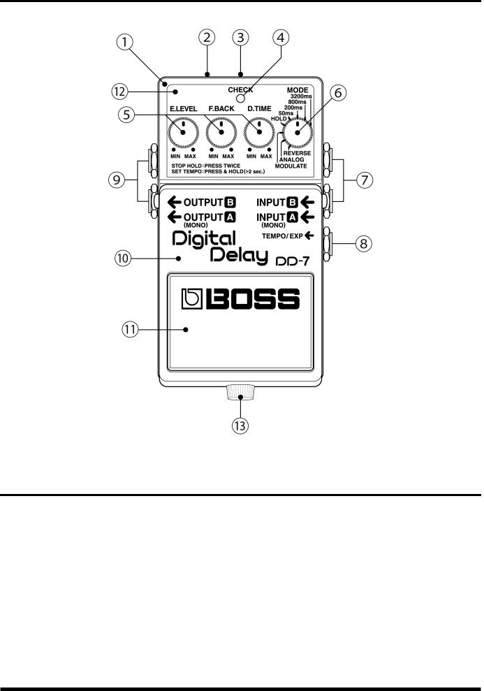
Location of Controls
Location of Controls Parts List
No. |
Part Code |
Part Name |
Description |
Q’ty |
1 |
75E593C0R0 |
CASE |
|
1 |
2 |
G2537516R0 |
PSA CAUTION |
CE 9V N225 |
1 |
3 |
13449717 |
ADAPTOR JACK |
HEC2392-01-150 |
1 |
4 |
F5029423R0 |
LED |
L-3VEGW |
1 |
5 |
G2477127R0 |
ROUND KNOB |
D-CUT (BLUE/BLACK) |
3 |
|
F3279852R0 |
POTENTIOMETER |
RD901-20-15FW-B54-006 |
3 |
6 |
G2477127R0 |
ROUND KNOB |
D-CUT (BLUE/BLACK) |
1 |
|
F3229206R0 |
POTENTIOMETER |
RD901-20-15FW-B50K-08Q7 8CLIC |
1 |
7 |
F3449150R0 |
JACK (STEREO+SW) |
2LJ-650NHW00 |
2 |
8 |
03344701 |
6.5MM JACK |
HTJ-064-12DS |
1 |
9 |
13449140R0 |
JACK(STEREO) |
HTJ-064-14D |
2 |
10 |
75E592T0R0 |
PEDAL |
|
1 |
11 |
22357304R0 |
PEDAL PLATE |
|
1 |
12 |
G2217798R0 |
PANEL PLATE |
|
1 |
13 |
40125101 |
THUMB SCREW |
M3X10 FE ZC |
1 |
4

May. 2008 |
DD-7 |
|
|
|
|
Exploded View
10
b
11
a
a
7 |
b |
|
|
|
|
|
|
6 |
|
2 |
d |
|
|
|
|
|
12 |
1 |
9 |
5 |
|
||
|
|
|
3
4
c
8
Exploded View Parts List
No. |
Part Code |
Part Name |
Description |
Q’ty |
1 |
13129710R0 |
SWITCH(PUSH) |
JM-0404 |
1 |
2 |
22267333R0 |
CUSHION |
|
1 |
3 |
F3419102R0 |
BATTERY CONNECTOR |
006P BATTERY SNAP |
1 |
4 |
G2537516R0 |
PSA CAUTION |
CE 9V N225 |
1 |
5 |
22357305R0 |
BOTTOM BASE |
|
1 |
6 |
22027851R0 |
BOTTOM COVER |
|
1 |
7 |
G2167301R0 |
INSULATING SHEET |
|
1 |
8 |
22157702R0 |
PEDAL GUIDE BUSH |
|
1 |
9 |
22177109R0 |
COIL SPRING |
|
1 |
10 |
22357304R0 |
PEDAL PLATE |
|
1 |
11 |
75E592T0R0 |
PEDAL |
|
1 |
12 |
75E593C0R0 |
CASE |
|
1 |
a |
40125134 |
NYLON WASHER 3X6X0.5 |
|
2 |
b |
H5019413R0 |
SCREW M3X10 |
BINDING MACHINE FEBC |
2 |
c |
H5029325R0 |
SCREW 3X6 |
B1FEBC |
4 |
d |
40125101 |
THUMB SCREW |
M3X10 FE ZC |
1 |
5

May. 2008 |
DD-7 |
|
|
|
|
Parts List
SAFETY PRECAUTIONS: The parts marked  have
have
safety-related characteristics. Use only listed parts for replacement.
Due to one or more of the following reasons,
parts with parts code ******** cannot be supplied as service parts.
•Part supplied only as a component in a complete assembly
•Copyright does not permit the part to be supplied
•Part is sold commercially
NOTE: The parts marked # are new. (initial parts) The description "Q'TY" means a necessary number of the parts per one product.
CASING
|
22357305R0 |
BOTTOM BASE |
|
1 |
|
22027851R0 |
BOTTOM COVER |
|
1 |
# |
75E593C0R0 |
CASE |
|
1 |
# |
G2217798R0 |
PANEL PLATE |
|
1 |
# |
75E592T0R0 |
PEDAL |
|
1 |
|
22357304R0 |
PEDAL PLATE |
|
1 |
KNOB, BUTTON |
|
|
|
|
|
|
|
|
|
# |
G2477127R0 |
ROUND KNOB |
D-CUT (BLUE/BLACK) |
4 |
JACK, EXT TERMINAL |
|
|
|
|
|
|
|
|
|
|
03344701 |
6.5MM JACK |
HTJ-064-12DS |
1 |
# |
F3449150R0 |
JACK (STEREO+SW) |
2LJ-650NHW00 |
2 |
|
13449140R0 |
JACK (STEREO) |
HTJ-064-14D |
2 |
|
13449717 |
ADAPTOR JACK |
HEC2392-01-150 |
1 |
SWITCH |
|
|
|
|
|
|
|
|
|
|
13129710R0 |
SWITCH(PUSH) |
JM-0404 |
1 |
PWB ASSY |
|
|
|
|
|
|
|
|
|
# |
75E593P0R1 |
MAIN SHEET ASSY |
|
1 |
|
* This unit includes the following parts. |
|
|
|
|
******** |
MAIN BOARD |
|
|
|
******** |
VR BOARD |
|
|
|
******** |
INPUT BOARD |
|
|
|
******** |
CTL BOARD |
|
|
|
******** |
LED BOARD |
|
|
DIODE |
|
|
|
|
|
|
|
|
|
|
F5029423R0 |
LED |
L-3VEGW |
1 |
RESISTOR |
|
|
|
|
|
|
|
|
|
|
F5399101R0 |
MTL.FILM RESISTOR |
0J (1608TYPE) |
12 |
# |
F5429516R0 |
MTL.FILM RESISTOR |
1R0 J(1608TYPE) |
12 |
POTENTIOMETER |
|
|
|
|
|
|
|
|
|
|
F3279852R0 |
POTENTIOMETER |
RD901-20-15FW-B54-006 |
3 |
# |
F3229206R0 |
POTENTIOMETER |
RD901-20-15FW-B50K-08Q7 |
1 |
|
|
|
8CLIC |
|
CONNECTOR |
|
|
|
|
|
|
|
|
|
|
F3419102R0 |
BATTERY CONNECTOR |
006P BATTERY SNAP |
1 |
WIRING, CABLE |
|
|
|
|
|
|
|
|
|
# |
F3487015R0 |
WIRING |
YELLOW 110X6EX6E (EXP) |
1 |
|
H4009408R0 |
WIRING 1007 |
WHITE 85X6X3 |
1 |
# |
F3477063R0 |
WIRING |
RIBBON CABLE 6P X80MM |
1 |
|
H4009498R1 |
WIRING 1P |
VIOLET L=160MM |
1 |
# |
H4009305R0 |
WIRING |
ORANGE 100X3X6 (OUTPUT) |
1 |
|
F3467053R0 |
WIRING 1007-26X3P |
L=65MM CONNECT X 1 |
1 |
# |
H4009610R0 |
WIRING |
GREY 100X3X6 (OUTPUT) |
1 |
|
H4009499R1 |
WIRING 1P |
GREEN L=160MM |
1 |
|
H4009597R0 |
WIRING 1007 |
BROWN 105X6X3 |
1 |
# |
H4009458R0 |
WIRING |
BLACK 45X6X6 (INPUT) |
1 |
# |
F3467058R1 |
INPUT WIRING |
BOARD IN CONNECTOR |
1 |
6

|
May. 2008 |
|
|
DD-7 |
|
|
|
|
|
|
|
|
|
|
|
|
|
|
SCREWS |
|
|
|
|
|
|
|
|
|
|
|
|
H5039158R0 |
WASHER M9X14X0.5T |
NI |
5 |
|
|
40125101 |
THUMB SCREW |
M3X10 FE ZC |
1 |
|
|
40125134 |
NYLON WASHER 3X6X0.5 |
|
2 |
|
|
22137709R0 |
WASHER 9.6X14X1.0 |
|
1 |
# |
G2137403R0 |
WASHER |
HALF MOON SHAPE |
1 |
|
|
|
H5019413R0 |
SCREW M3X10 |
BINDING MACHINE FEBC |
2 |
|
|
H5029325R0 |
SCREW 3X6 |
B1FEBC |
5 |
|
|
H5039205R0 |
TOOTH WASHER |
9.1X13 |
5 |
|
|
H5039510R0 |
NUT M9X12X2T NI |
|
5 |
|
|
H5039521R0 |
NUT M7 |
|
4 |
|
PACKING |
|
|
|
|
|
|
|
|
|
|
|
|
G2627738R0 |
INNER BOX |
|
1 |
# |
G2627793R0 |
PACKING CASE |
|
1 |
|
|
MISCELLANEOUS |
|
|
|
|
|
|
|
|
|
|
|
|
H2369451R0 |
LED SPACER |
LEDH-5 5MM 3P |
1 |
|
|
G2537516R0 |
PSA CAUTION |
CE 9V N225 |
1 |
|
|
22177109R0 |
COIL SPRING |
|
1 |
|
|
22267333R0 |
CUSHION |
|
1 |
|
|
G2167301R0 |
INSULATING SHEET |
|
1 |
|
|
22157702R0 |
PEDAL GUIDE BUSH |
|
1 |
|
|
22257257R0 |
EARTH TERMINAL |
|
2 |
|
ACCESSORIES (Standard) |
|
|
|
|
|
|
|
|
|
|
# |
G6017474R0 |
OWNER’S MANUAL |
JAPANESE |
1 |
|
# |
G2507366R0 |
OWNER’S MANUAL |
ENGLISH |
1 |
|
# |
G2547154R0 |
MODE LABEL |
|
1 |
|
# |
G2547160R0 |
APPLICATION LABEL |
|
1 |
|
7

May. 2008 |
DD-7 |
|
|
|
|
Verifying the Version
Number
1.Connect an AC adaptor.
2.Turn down all controls all the way counterclockwise.
3.Holding down the foot pedal and inserting a plug into the INPUT jack makes the CHECK LED light up.
*Continue holding down the pedal until the LED goes dark.
After approximately 2 seconds, the CHECK LED goes dark.
*The CPU and DSP checks are performed before the LED goes dark as just described. If a problem is found in the CPU, DSP, or the like, the LED may not go out.
After approximately 1 second the CHECK LED flashes, and the number of flashes indicates the version.
1 flash: |
Ver. 1.00 |
2 flashes: |
Ver. 1.01 |
3 flashes: |
Ver. 1.02 |
4.After the version display, execution shifts to the Test Mode.
Performing a Factory Reset
This product has no factory-reset feature.
Updating the System
A system update cannot be performed for this product. If an update is required, replace with an updated circuit board.
8
 Loading...