


 Loading...
Reference Manual
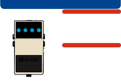
Panel Descriptions
1 2
3 


 4
4


 5
5
6
7
2
1 DC IN jack
Accepts connection of an AC Adaptor (PSA series; sold separately). By using an AC Adaptor, you can play without being concerned about how much battery power you have left.
*If there are batteries in the unit while an AC adaptor is being used, normal operation will continue should the line voltage be interrupted (power blackout or power cord disconnection).
*Use only the specified AC adaptor (PSA-series).
*If the AC adaptor is connected while power is on, the power supply is drawn from the AC adaptor.
2 CHECK indicator
This is a combination indicator, which indicates whether the effect is on or off, indicates the various functions, and functions as the battery check indicator.
The indicator lights when an effect is ON.
*If this indicator goes dim or no longer lights while an effect is ON, or when the functions are indicated, the battery is near exhaustion and should be replaced immediately. For instructions on changing the batteries, refer to “Changing the Battery” (p. 21).
*The CHECK indicator shows whether the effect is on or off, and indicates the different functions. It does not indicate whether the power to the device is on or not.

Panel Descriptions
3OUTPUT-A (MONO) jack, OUTPUT-B jack
The output jacks are used to connect the unit to an amplifier or another effects unit.
*The unit’s functions differ according to how it is connected. Refer to “Setting the Output Method” (p. 15).
4INPUT-A (MONO) jack, INPUT-B jack
These jacks accept input signals (coming from a guitar, some other musical instrument, or another effects unit).
*The unit’s functions differ according to how it is connected. Refer to “Setting the Output Method” (p. 15).
*The INPUT-A (MONO) and INPUT-B jacks double as power switches. Power to the unit is turned on when you plug into the INPUT-A (MONO) or INPUT-B jack; the power is turned off when the cable is unplugged. Be sure to disconnect any cord plugged into the INPUT-A (MONO) or INPUT-B jack when not using this effects device.
5 TEMPO/EXP jack
This jack is for connecting a footswitch (FS-5U, FS-6, FS-7; sold separately) or an expression pedal (Roland EV-5, FV-500H, FV-500L, EV-30; sold separately).
This jack lets you use a footswitch to set the tempo, control the loop, or turn TWIST on/off, or use an expression pedal to control various parameters.
*For details, refer to “Setting the Tempo Using a Footswitch” (p. 12),
“Using a footswitch to control the loop function” (p. 14), “Using the TWIST Function” (p. 14), or
“Control Using an Expression Pedal” (p. 19).
6 Pedal switch
This is used for switching the effect on and off, and for switching between the different functions.
7 Thumbscrew
When this screw is loosened, the pedal will open, allowing you to change the battery.
*For instructions on changing the battery, refer to “Changing the Battery” (p. 21).
3

Panel Descriptions
8 |
9 |
10 |
11 |
* This cannot be used in LOOP mode. |
* In GLT mode, this adjusts the depth of the GLT effect.
* Oscillation may occur when the knob is set at certain positions.
|
|
10 |
[TIME] knob |
|
|
|
This adjusts the delay time. Turning the knob clockwise |
|
|
|
lengthens the delay time. |
|
|
* |
This cannot be used in LOOP mode. |
|
|
* |
The delay times that can be set vary according to the |
|
|
|
position of the [MODE] knob. |
8 |
[E.LEVEL] knob |
11 |
[MODE] knob |
|
This adjusts the volume of the effect sound. Turn the knob |
|
This switches the delay effect. |
|
|
|
|
|
clockwise to increase the effect sound. When set at the three |
12 |
[CARRYOVER] switch |
|
o’clock position, the effect is played at the same volume as the |
||
|
direct sound. |
|
This selects whether the delay sound remains (ON) or does not |
|
* When the [E.LEVEL] knob is set to MAX while in REVERSE |
|
remain (OFF) when you turn off the effect. |
|
mode, only the effect sound is output, with the effect sound |
|
|
|
at the same level as the input sound. |
|
|
9 |
[FEEDBACK] knob |
|
12 |
|
This adjusts the feedback level. The number of times the delay |
|
|
|
|
|
|
|
sound is repeated increases as the knob is turned to the right. |
|
|
4

Panel Descriptions
Characteristics of each mode
MODE knob |
Explanation |
Delay time |
|
|
|
|
|
STANDARD |
Clear digital delay. |
20–800 ms |
|
|
|
|
|
ANALOG |
Mild analog delay. |
20–800 ms |
|
|
|
|
|
TAPE |
Sound with the modulation that is distinctive of a tape echo unit. |
20–800 ms |
|
WARM |
Mild digital delay. |
20–800 ms |
|
REVERSE |
Delay played backward. |
300–5000 ms |
|
|
|
|
|
+RV |
Delay with reverb. |
20–800 ms |
|
|
|
|
|
SHIM |
Delay with pitch-shifted sound added. |
200–800 ms |
|
MOD |
Digital delay with modulation. |
20–800 ms |
|
WARP |
Creates a dreamlike sound. |
20–800 ms |
|
|
|
|
|
GLT |
Creates a machine-gun-like sound. |
10–400 ms |
|
|
|
|
|
LOOP |
Records your performance, and repeatedly plays it back. |
40 sec. *1 |
|
For more information, refer to “Using the LOOP (Overdubbing) Function” (p. 13). |
|||
|
|
||
|
|
|
*1:In LOOP mode, the maximum recording time is 20 seconds for stereo input or 40 seconds for mono input.
* If you specify the long delay output setting, the delay time is doubled. For details, refer to “Setting the Output Method” (p. 15).
5

Connections
AC Adaptor (PSA series; sold separately)
Guitar Amplifier
Keyboard
Electric Guitar
Footswitch (FS-6 etc.)
Expression Pedal (Roland EV-5 etc.)
6 |
You can obtain a variety of different delay effects by changing how the connections are made. |
For more information, refer to “Setting the Output Method” (p. 15). |
Connections
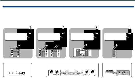
Footswitch connections
Refer to the diagrams for details on the appropriate cables to use and the setting of the polarity switch.
*When connecting a footswitch, you must turn off the power before connecting or disconnecting cables. Failure to observe this precaution will cause malfunctions.
Connect to TEMPO/EXP jack |
Connect to TEMPO/EXP jack |
Connect to TEMPO/EXP jack |
Connect to TEMPO/EXP jack |
|
Connecting one FS-5U unit |
Connecting two FS-5U units |
Connecting one FS-6 unit |
Connecting one FS-7 unit |
|
1/4” phone type, |
Stereo 1/4” phone type, |
|
Stereo 1/4” phone type, |
Stereo 1/4” phone type, |
1/4” phone type |
1/4” phone type × 2 |
|
Stereo 1/4” phone type |
Stereo 1/4” phone type |
|
RING |
TIP |
|
|
|
|
|
A&B |
A&B |
FS-5U POLARITY switch |
FS-6 MODE/POLARITY switch |
FS-7 MODE/POLARITY switch |
7
Loading...