


BV7200 |
Multi-Media Disc Player |
with 3.2-inch TFT LCD Display |
Congratulations on your purchase of a  Multi-Media Disc Player.
It has been designed, engineered and manufactured to bring you the highest level of performance and quality, and will afford you years of listening pleasure.
Thank you for making a your choice for mobile video entertainment.
USER’S MANUAL
page CONTENTS
2Safety Information
3Installation
5 Using the Detachable Front Panel
6Wiring Diagram
7Operation
7Features and Controls
8 Using the Remote Control
9 General Operation
10Radio Operation
11AV Menu Settings
15Disc Operation
19Data Disc Play Operation
19USB Playback
20Memory Card Play Operation
20AV IN Operation
21 Setup
21System Setup
22Language Setup
23Audio Setup
23 Digital Setup
23 More About This Player
25Specification
26Troubleshooting
BV7200 User’s Manual - page 1
Safety Information
CAUTION:
This mobile DVD player is a Class 1 laser product. However, this mobile DVD player uses a visible/invisible laser beam which could cause hazardous radiation exposure if directed. Be sure to operate the mobile DVD player correctly as described in this manual.
Use of controls or adjustments or performance of procedures other than those specifi ed herein may result in hazardous radiation exposure.
Do not open covers and do not attempt to repair this product yourself. Refer servicing to qualifi ed personnel.
WARNING:
-To reduce the risk of fi re or electric shock, do not expose this equipment to rain or moisture.
-To reduce the risk of fi re or electric shock, and annoying interference, use only the recommended accessories.
-This device is intended for continuous operation.
This product incorporates copyright protection technology that is protected by method claims of certain U.S. patents and other intellectual property rights owned by Macrovision Corporation and other rights owners. Use of this copyright protection technology must be authorized by Macrovision Corporation, and is
intended for home and other limited viewing uses only unless otherwise authorized
by Macrovision Corporation. Reverse engineering or disassembly is prohibited.
Region Management Information
This mobile DVD Player is designed and manufactured to respond to the Region Management Information that is recorded on a DVD disc. If the Region number described on the DVD disc does not corre-
spond to the Region number of this Mobile DVD Player, this Mobile DVD Player cannot play this disc.
DISC NOTES
You can playback the following discs: DVD VIDEO/DVD AUDIO
VIDEO CD/AUDIO CD
MP3/WMA/JPEG/MPEG4
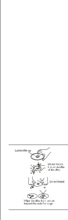
Handling and Cleaning
-Dirt, dust, scratches and warped discs will prevent proper operation.
-Do not place stickers or make scratches on discs.
-Do not bend discs.
-A disc should always be kept in its case when not in use to prevent damage.
-Do not place discs in the following places: 1.Direct sunlight.
2.Dirty, dusty and damp areas. 3.Near car heaters.
4.On the seats or dashboard.
Disc Cleaning
Use a dry soft cloth to wipe the surface. If the disc is quite dirty, use a soft cloth slightly moistened with isopropyl (rubbing) alcohol. Never use solvents such as benzene, thinner or conventional record cleaners as they may mar the surface of the disc.
BV7200 User’s Manual - page 2
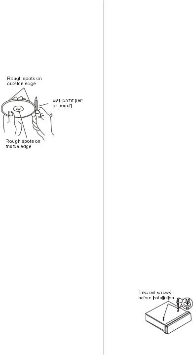
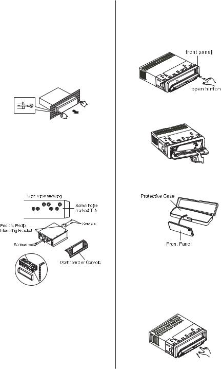
Preparing new discs with rough spots
A new disc may have rough edges on its inside and outside edges. If a disc with rough edges is used, the disc will not be properly seated and the player will not play the disc. Therefore, remove the rough edges in advance by using a ballpoint pen or pencil as shown on the right. Press the side of the pen or pencil against the inside and outside edges of the disc.
Installation
Notes:
-Choose a mounting location where the unit will not distract the driver.
-Before the installation of the unit, connect the wiring temporarily and make sure it is all connected properly and the unit and the system works.
-Use only the parts included with the unit
to ensure proper installation. The use of unauthorized parts can cause malfunctions.
-Consult with your dealer if installation requires the drilling of holes or other modifi cations of the vehicle.
-Install the unit where it does not get in the driver’s way and cannot injure the passenger if there is a sudden stop, like an emergency stop.
-If installation angle exceeds 30° from horizontal, the unit may not perform properly.
-Avoid installing the unit where it will be subject to high temperature, such as from direct sunlight, or from hot air, from the heater, or where it would be subject to dust, dirt or excessive vibration.
DIN mounting options
This unit can be installed either from the ‘Front’ (conventional DIN Front-mount) or the ‘Rear’ (DIN Rear-mount installation using the threaded holes on the sides of the chassis). For details, refer to the following illustrated installation methods.
Remove transit screws before installation
Before installing the unit, please remove the two transit screws.
BV7200 User’s Manual - page 3
1. DIN front-mount (method A)
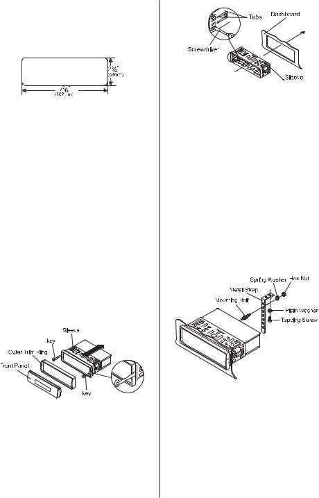
Installation opening
This unit can be installed in any dashboard opening with dimensions as shown below:
Installing the unit
Be sure to test all connections fi rst, then follow these steps to install the unit.
1. Make sure the ignition is turned off. Disconnect the cable from the vehicle battery negative (-) terminal.
2.Disconnect the wire harness and the antenna.
3.Press the RELEASE ( ) on the front panel and remove the control panel (for details, refer to ‘Using the Detachable Front Panel’).
4.Lift the top of the outer trim ring. Then pull it out to remove it.
5.The two supplied keys release tabs inside the unit’s sleeve so you can remove it. Insert the keys as far as they will go (with the notches facing up) into the appropriate slots at the center of the left and right sides of the unit. Then slide the sleeve off the back of the unit.
6. Mount the sleeve by inserting it into the opening of the dashboard and bend open the tabs located around the sleeve with a screwdriver. Not all tabs will be able to
make contact, so examine the opening to determine which tabs will be most effective. Bend open the appropriate tabs behind the dashboard to secure the sleeve in place.
7. Reconnect the wire harness and the antenna, being careful not to pinch any wires or cables.
8.Slide the unit into the sleeve until it locks into place.
9.To further secure the unit, use the supplied metal strap to secure the back of the unit in place. Use the supplied hardware (Hex Nut (M5mm) and Spring Washer) to attach one end of the strap to the mounting bolt on the back of the unit. If necessary, bend the metal strap to fi t your vehicle’s mounting surface. Then use the supplied hardware (Tapping Screw (5x25mm) and Plain Washer) to attach the other end of the metal strap to a solid metal part of the vehicle under the dashboard. This strap also helps ensure proper electrical grounding of the unit.
10. Reconnect the cable to the vehicle battery’s negative (-) terminal. Then replace the outer trim ring and install the unit’s front panel (see the steps of ‘to install the front panel’).
Removing the unit
1. Make sure the ignition is turned off, and
BV7200 User’s Manual - page 4
then disconnect the cable from the vehicle battery negative (-) terminal.
2.Remove the metal strap attached to the back of the unit (if present).
3.Press the release button to remove the front panel.
4.Lift the top of the outer trim ring then pull it out to remove it.
5.Insert both of the supplied keys into the slots at the middle left and right sides of the unit then pull the unit out of the dashboard.
2. DIN rear-mount (method B)
If your vehicle is a Nissan or Toyota, follow these mounting instructions: Use the screw holes marked T (Toyota) or N (Nissan) located on both sides of the unit to fasten the unit to the factory radio mounting brackets supplied with your car.
Fasten the unit to the factory radio mounting brackets. Align the screw holes on the bracket with the screw holes on the unit, and then tighten the screws (5x5mm) on each side.
Note: The outer trim ring, sleeve and the metal strap are not used for method B installation.
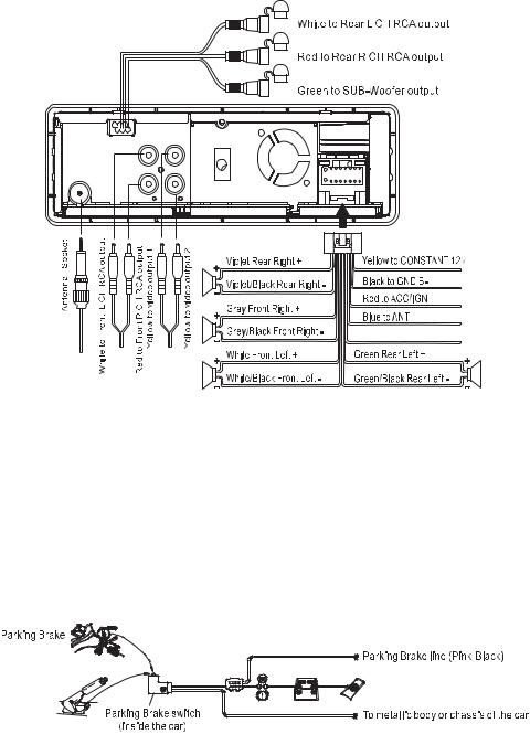
Using the Detachable Front Panel
Removing the front panel
1. Press the release  button (7) to fl ip down the front panel.
2. Pull off the front panel.
3. Store the front panel in its protective case.
Installing the front panel
To install the front panel, insert it as shown in the drawing below. Be sure it is fully inserted. If not, the display or some of the keys may not function properly.
BV7200 User’s Manual - page 5
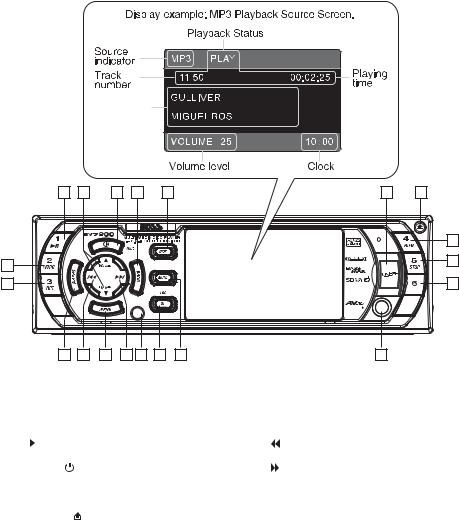
Wiring Diagram
Pink/Black to Parking Brake B-
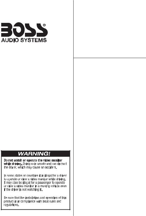
WATCHING THE VIDEO MONITOR IS FORBIDDEN WHILE DRIVING:
The “PARKING BRAKE” wire must be connected to the parking brake system of your car. The LCD screen will display video images ONLY when the parking brake is engaged.
If the parking brake is not engaged, the screen will display the message “DISABLED WHILE DRIVING”. This is a safety feature designed to prevent the driver from watching a video while driving. The video output of this unit is not affected by this.
Note: In Radio Mode or CD/MP3 Mode images will be displayed on the monitor whether or not the parking brake is engaged.
Connecting the Parking Brake line to the parking brake system built in the car
BV7200 User’s Manual - page 6
Operation
Features and Controls
Front Panel
Disc
Information
1 |
2 |
3 |
4 |
5 |
6 |
7 |
|
|
|
|
|
|
18 |
8 |
|
|
|
|
|
19 |
|
|
|
|
|
|
|
9 |
|
|
|
|
|
20 |
10 |
11 |
12 |
13 |
14 |
15 |
16 |
17 |
Front Panel Button Legend
1 |
1 |
|
|
|
11 |
|
|
(Fast Reverse), TUNE/TRACK Down |
|
|
|
|
|
||||
2 |
VOL+/- |
|
12 |
MENU |
||||
3 |
POWER ( |
) |
13 |
|
|
(Fast Forward), TUNE/TRACK Up |
||
4 |
BAND |
|
14 |
IR Sensor |
||||
5 |
DISP (Display) |
15 |
|
ST (Stereo/Mono select), |
||||
6 |
USB Port |
|
|
|
LOC (Local/Distance select) |
|||
7 |
RELEASE ( |
) |
16 |
|
MUTE (turns audio off) |
|||
8 |
2 |
INTRO (Intro Scan) |
17 |
|
A/V Input Connector |
|||
9 |
3 |
RPT (Repeat Mode select) |
18 |
4 |
RDM (Random Playback Mode select) |
|||
10 |
AS•PS (Automatic Search/Program |
19 |
5 |
STOP |
||||
|
Search) |
|
20 |
6 |
|
|||
BV7200 User’s Manual - page 7
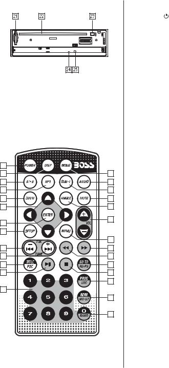
Back of front panel
21SD/MMC card slot
22Disc slot
23EJECT ( )
)
24LED Warning light
25RESET button
|
Remote Control |
1 |
|
2 |
14 |
3 |
15 |
4 |
16 |
5 |
17 |
6 |
18 |
7 |
19 |
|
|
8 |
|
|
20 |
9 |
21 |
10 |
22 |
11 |
23 |
12 |
24 |
|
25 |
13 |
|
|
26 |
|
27 |
Remote Control Button Legend
1 POWER ( )
2DISP (Display)
3 A > B (repeat section from A to B)
4RPT (Repeat Mode select)
5ZOOM
6Cursor (arrow) keys: UP/DOWN/RIGHT/LEFT
7ENTER
8SETUP
9 (TUNE/TRACK Down, Last Track)
10
 (TUNE/TRACK Up, Next Track)
11TITLE (DVD Title Menu),
PBC (Playback Control Mode)
12PLAY/PAUSE (
 )
)
13Numeric buttons 1-9
14MODE (Input Mode select)
15AUDIO (Audio Setup select)
16SUBT (Subtitle language select)
17MUTE (turns audio off)
18ANGLE (Camera angle selection for some DVDs)
19VOL +/-
20MENU
21 (Fast Forward)
22 (Fast Reverse)
23GO TO, AS•PS (Automatic Search / Program Search)
24STOP ( )
)
25PROG (Programmed Play mode) LOC (Local/Distance select)
26RDM (Random Playback mode) MO•ST (Stereo/Mono select)
27BAND, (Numeric button) 0
Using the Remote Control
Preparing The Remote Control
*Before using the remote control for the fi rst time, please remove the clear strip from the bottom of the remote control.
*This remote control is designed to be used within 6 feet of the remote sensor on the head unit, and within a range from 30° left to 30° right of the sensor.
*If direct sunlight is falling on the remote sensor, it may interfere with the ability of the remote to communicate with the head unit.
*This remote control is a precision device.
BV7200 User’s Manual - page 8
 Loading...