

Owner's Manual
DCAC
AC & BATTERY
POWERED
FET
1

Thank you, and congratulations on your choice of BOSS GEB-7 Bass Equalizer.
Before using this unit, carefully read the sections entitled: “USING THE UNIT SAFELY”
and “IMPORTANT NOTES” (separate sheet). These sections provide important information
concerning the proper operation of the unit. Additionally, in order to feel assured that you
have gained a good grasp of every feature provided by your new unit, this manual should
be read in its entirety. The manual should be saved and kept on hand as a convenient
reference.
©1995 BOSS Corporation
All right reserved. No part of this publication may be reproduced in any form without the
written permission of BOSS Corporation.
2

FEATURES
• The BOSS GEB-7 is a 7-band equalizer designed specifically for electric bass.
• Since it allows for a broad range of frequency settings, even five string basses can be
accommodated.
• The unit is designed to provide the optimum Q (equalizer's bandwidth) for bass for each
center frequency. While making it easy to obtain the most delicate of nuances, it also
allows for radically unique settings as well.
• The GEB-7 allows you to adjust the output level of the equalized sound so it matches
the level of the input sound.
3

PANEL DESCRIPTIONS
1
3
4
5
4
1. AC Adaptor Jack
2
Accepts connection of an AC Adaptor (optionally available BOSS PSA-Series). By
using an AC Adaptor, you can play without
being concerned about how much battery
power you have left.
* You may find that it is a good idea to keep a
battery installed in the unit even while using
6
an adaptor. That way your playing won’t be
disrupted even if the adaptor is accidentally
disconnected.-
* If you are going to use an AC adaptor, be sure
to use the specified unit (BOSS PSA-Series).
Use of any other adaptor may result in damage, malfunction or electric shock.
Also, if you are not going to be using it for an
extended period of time, disconnect the AC
adaptor from the AC outlet.

2. CHECK Indicator
This indicator shows whether an effect is
ON/OFF, and also doubles as the Battery
Check indicator.
The indicator lights when an effect is ON.
If this indicator goes dim or no longer lights
while an effect is ON, the battery is near
exhaustion and should be replaced immediately.
3. OUTPUT Jack
The output jacks are used to connect the
unit to amplifiers or other devices.
4. Pedal Switch
This switch turns the effects ON/OFF.
5. Thumbscrew
This thumbscrew is loosened to open the
pedal, allowing battery replacement. For
instructions on how to replace the battery,
please refer to “CHANGING THE BATTERY”.
6. INPUT Jack
This jack accepts input signals (coming
from a bass guitar, some other musical
instrument, or another effects unit).
* The INPUT jack also serves as the power
switch. Power is turned on whenever a plug is
inserted into the INPUT jack, and is turned off
when the plug is disconnected. When not
using the unit, you should disconnect any
cord connected to the INPUT jack.
5
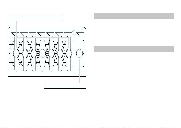
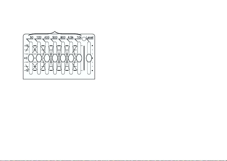
Equalizer Control Knobs
800 4.5k 10k50040012050 Level
+
15
Equalizer Control knobs
These knobs allow you to boost or cut the
center frequency of 50, 120, 400, 500,
800, 4.5 k or 10 kHz within +/-15 dB.
0
Level Control Knob
This knob allows you to adjust the output
level of the effect sound to minimize the
-
15
level difference between the effect and
direct sounds.
Level Control Knob
6
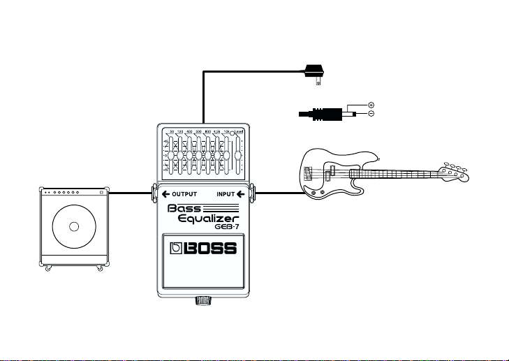
MAKING THE CONNECTIONS
Amplifier
AC Adaptor (PSA-Series ; Optional)
OUT 9V DC / 200mA
Electric Bass
7

* Inserting a plug into the INPUT Jack will automatically switch the unit on.
* To prevent malfunction and/or damage to speakers or other devices, always turn down the
volume, and turn off the power on all devices before making any connections.
* If there are batteries in the unit while an AC adaptor is being used, normal operation will continue
should the line voltage be interrupted (power blackout or power cord disconnection).
* Once the connections have been completed, turn on power to your various devices in the order
specified. By turning on devices in the wrong order, you risk causing malfunction and/or damage
to speakers and other devices.
When powering up: Turn on the power to your guitar amp last.
When powering down: Turn off the power to your guitar amp first.
* Always make sure to have the volume level turned down before switching on power. Even with
the volume all the way down, you may still hear some sound when the power is switched on, but
this is normal, and does not indicate a malfunction.
* When operating on battery power only, the unit’s indicator will become dim when battery power
gets too low. Replace the battery as soon as possible.
* The CHECK indicator shows whether the effect is being applied or not. It does not indicate
whether the power to the device is on or not.
8
OPERATING THE UNIT
3
When you have made the necessary
1.
4
connections, set the knobs as shown in
the illustration.
2. Depress the pedal switch to turn the
effect on. (Make sure that the CHECK
Indicator lights.)
3. Adjust the tone using the relevant Equal-
izer Control Knobs.
4. Adjust the output level using the Level
Control Knob, to minimize the level
difference between the effect and direct
sounds.
9

CHANGING THE BATTERY
When the indicator goes dim or no longer lights
while an effect is on, it means that the battery is
nearly dead and must be replaced.
Replace the battery following the steps below.
Thumbscrew
Pedal
Spring Base
Battery
Housing
Coil Spring
Guide
Bush
Hole
Battery Snap Cord
Battery Snap
9V Battery
10
1. Loosen the thumbscrew at the front of the
pedal, then lift the pedal upwards to open the
unit.
* The thumbscrew can be left in the pedal
while changing the battery.
2. Remove the old battery from the battery
housing, and remove the snap cord connected to it.
3. Connect the snap cord to the new battery, and
place the battery inside the battery housing.
* Be sure to carefully observe the battery+s
polarity (+ versus -).
4. Slip the coil spring onto the spring base on the
back of the pedal, then close the pedal.
* Carefully avoid getting the snap cord caught
in the coil spring.
5. Finally, insert the thumbscrew into the guide
bush hole and fasten it securely.

FREQUENCY RESPONSE
+
15
)
dB
(
0
LEVEL
-15
10
100 1k 10k
FREQUENCY(Hz
)
11

SAMPLE SETTING
Standard Rock
Heavy Metal
800 4.5k 10k50040012050 Level
+
15
0
-
15
+
15
0
-
15
800 4.5k 10k50040012050 Level
Slapping Play Bass Amplifier Simulation
800 4.5k 10k50040012050 Level
+
15
0
-
15
+
15
0
-
15
800 4.5k 10k50040012050 Level
12

SETTING MEMO
800 4.5k 10k50040012050 Level
+
15
0
-
15
800 4.5k 10k50040012050 Level
+
15
0
-
15
+
15
0
-
15
+
15
0
-
15
800 4.5k 10k50040012050 Level
800 4.5k 10k50040012050 Level
13

SPECIFICATIONS
GEB-7 : Bass Equalizer
Nominal Input Level ................. -20 dBu
Input Impedance ...................... 1 MΩ
Nominal Output Level .............. -20 dBu
Output Impedance ................... 1 kΩ
Recommended Load Impedance..
Residual Noise Level................. -100 dBu (IHF-A, Typ.)
Variable Range ......................... Equalizer Control : +/-15 dB
Controls.................................... Pedal Switch
Indicator................................... CHECK Indicator (serves also as battery check indicator)
Connectors ............................... INPUT Jack
Power Supply ........................... DC 9 V: Dry Battery 9 V type (6F22/9 V), AC Adaptor
Current Draw ........................... 16 mA (DC 9 V)
14
10 kΩ or greater
Level Control : +/-15 dB
Equalizer Control Knobs (50, 120, 400, 500, 800, 4.5 k, 10 kHz)
Level Control Knob
OUTPUT Jack
AC Adaptor Jack (DC 9 V)
* Expected battery life under continuous use :
Carbon : 12 hours
These figures will vary depending on the actual conditions of use.

Dimensions............................... 73 (W) x 129 (D) x 59 (H) mm
Weight...................................... 440 g / 1 lb (including battery)
Accessories ............................... Owner’s Manual
Options .................................... AC Adaptor PSA-Series
* 0 dBu = 0.775 V rms
* In the interest of product development, the specifications and/or appearance of this unit are
subject to change without prior notice.
2-7/8 (W) x 5-1/8 (D) x 2-3/8 (H) inches
Dry Battery 9 V type (6F22/9 V)
Leaflet
(“USING THE UNIT SAFELY,” “IMPORTANT NOTES,” and “Information”)
This product complies with the requirements of
For EU Countries
European Directive 89/336/EEC.
15

16
2601720402
 Loading...