


Tronic TR4500T 50 EB
Bosch Tronic TR4500T 50 EB, Tronic TR4500T 30 EB, Tronic TR4500T 80 EB, Tronic TR4500T 150 EB, Tronic TR4500T 100 EB Installation Manual
...
User and Installation manual
Electrical storage water tank
Tronic
TR4500T 30|50|80|100|120|150 EB
6 720 884 457 (2018/02) DK-(en)
2
Index
Tronic – 6 720 884 457 (2018/02)
Index
1 Key to symbols and safety instructions . . . . . . . . . . 3
1.1 Key to symbols . . . . . . . . . . . . . . . . . . . . . . . 3
1.2 Security Measures . . . . . . . . . . . . . . . . . . . . . 3
2 Technical Characteristics and dimensions . . . . . . . 6
2.1 Intended use . . . . . . . . . . . . . . . . . . . . . . . . . 6
2.2 Type overview . . . . . . . . . . . . . . . . . . . . . . . . 6
2.3 Appliance Description . . . . . . . . . . . . . . . . . . 6
2.4 Anticorrosion protection . . . . . . . . . . . . . . . . 6
2.5 Accessories (included in the appliance
packaging) . . . . . . . . . . . . . . . . . . . . . . . . . . .6
2.6 Technical specifications . . . . . . . . . . . . . . . . 7
2.7 Dimensions . . . . . . . . . . . . . . . . . . . . . . . . . . 8
2.8 Electrical wiring diagram . . . . . . . . . . . . . . . 9
3 Regulations . . . . . . . . . . . . . . . . . . . . . . . . . . . . . . . . . 10
4 Transport . . . . . . . . . . . . . . . . . . . . . . . . . . . . . . . . . . 10
4.1 Transport, storage and recycling
regulations . . . . . . . . . . . . . . . . . . . . . . . . . 10
5 Installation . . . . . . . . . . . . . . . . . . . . . . . . . . . . . . . . . 10
5.1 Important notes . . . . . . . . . . . . . . . . . . . . . . 10
5.2 Siting the appliance . . . . . . . . . . . . . . . . . . . 10
5.3 Wall mounting . . . . . . . . . . . . . . . . . . . . . . . 11
5.4 Water connection . . . . . . . . . . . . . . . . . . . . 11
5.5 Electrical connections . . . . . . . . . . . . . . . . . 13
5.6 Start-up . . . . . . . . . . . . . . . . . . . . . . . . . . . . 14
6 Use . . . . . . . . . . . . . . . . . . . . . . . . . . . . . . . . . . . . . . . . 15
6.1 Turning the appliance on/off . . . . . . . . . . . 15
6.2 Operating the heater – manual setting . . . 15
6.3 Operation of the heater in
the "BOOST" mode . . . . . . . . . . . . . . . . . . . 15
6.4 The Anti-Legionella Function . . . . . . . . . . . 15
6.5 Emptying the appliance . . . . . . . . . . . . . . . 16
7 Environment / disposal . . . . . . . . . . . . . . . . . . . . . . . 16
8 Inspection/Maintenance . . . . . . . . . . . . . . . . . . . . . 17
8.1 User information . . . . . . . . . . . . . . . . . . . . . 17
8.1.1 Cleaning . . . . . . . . . . . . . . . . . . . . . . . . . . . . 17
8.1.2 Safety valve verification . . . . . . . . . . . . . . . 17
8.1.3 Safety valve . . . . . . . . . . . . . . . . . . . . . . . . . 17
8.1.4 Maintenance and repair . . . . . . . . . . . . . . . 17
8.2 Periodic maintenance work . . . . . . . . . . . . 17
8.2.1 Functionality verification . . . . . . . . . . . . . . 17
8.2.2 Magnesium Anode . . . . . . . . . . . . . . . . . . . . 17
8.2.3 Periodic cleaning . . . . . . . . . . . . . . . . . . . . . 18
8.2.4 Long standing - non working
(more than 3 months) . . . . . . . . . . . . . . . . .18
8.3 Required actions after any maintenance
work has been carried out . . . . . . . . . . . . . .18
9 Problems . . . . . . . . . . . . . . . . . . . . . . . . . . . . . . . . . . . 19
9.1 Indication of errors . . . . . . . . . . . . . . . . . . . . . . . . . . . 19
3
Key to symbols and safety instructions
Tronic – 6 720 884 457 (2018/02)
1 Key to symbols and safety instructions
1.1 Key to symbols
Warnings
The following keywords are defined and can be used in this
document:
• NOTICE indicates a situation that could result in damage to
property or equipment.
• CAUTION indicates a situation that could result in minor to
medium injury.
• WARNING indicates a situation that could result in severe
injury or death.
• DANGER indicates a situation that will result in severe
injury or death.
Important information
Additional symbols
1.2 Security Measures
Installation
▶ Installation must only be carried out
by an authorised service.
▶ IEC 60364-7-701 must be observed
when installing the appliance and or
electrical accessories.
▶ The appliance must be installed in a
room free from the risk of frost.
▶ First connect the appliance
hydraulically and fill with water, then
connect the power supply.
▶ During the installation isolate the
appliance from the power supply.
▶ In a closed, pressurised system of
installation, it is obligatory to install a
safety valve on the inlet pipe with a
rated pressure of 0.6 MPa (6 bar),
0.9 MPa (9 bar) or 1.0 MPa (10 bar)
(see the label), which prevents the
elevation of pressure in the boiler by
more than 0.1 MPa (1 bar) above the
rated pressure.
▶ Water may drip from the outlet
opening of the safety valve, so the
outlet opening should be set to
atmospheric pressure.
▶ The outlet of the safety valve should
be installed facing downwards and in
a non-freezing area.
▶ To ensure proper functioning of the
safety valve, the user should perform
regular controls to remove limescale
and make sure the safety valve is not
blocked.
Warnings in this document are identified by
a warning triangle printed against a grey
background.
Keywords at the start of a warning indicate
the type and seriousness of the ensuing risk
if measures to prevent the risk are not taken.
This symbol indicates important information
where there is no risk to people or property.
Symbol Explanation
▶ Step in an action sequence
Cross-reference to another part of the document
•List entry
– List entry (second level)
Table 1

4
Key to symbols and safety instructions
Tronic – 6 720 884 457 (2018/02)
Installation and conversion
▶ Only permit an authorised service to
install this appliance.
▶ Do not install a stop valve between
the water heater and the safety valve,
because it will impair the pressure
protection of the heater!
▶ Before connecting it to the power
supply, the water heater must be
filled with water!
▶ The heater is equipped with an
additional thermal cut-off for
protection in case of failure of the
operating thermostat. In this case,
however, the temperature of the
water in the heater can reach up to
130 °C according to the safety
standards. During the water supply
installation, the possibility of
temperature overloads should be
taken into account.
▶ If the heater is to be disconnected
from the power supply, please drain
any water from the heater to prevent
freezing.
▶ Water can be drained from the heater
through the boiler inlet pipe. For this
purpose it is advisable to install a Telement with an outlet valve between
the inlet pipe and safety valve.
▶ Never obstruct the safety valve outlet.
▶ During the heat-up, water may be
expelled from the safety valve.
Maintenance
▶ Only authorised technicians are
permitted to service this appliance.
▶ Isolate the appliance from its power
supply before commencing any
maintenance work on the appliance.
▶ Customers are responsible for the
safety and environmental
compatibility of the appliance as well
as its maintenance.
▶ Use only original spare parts.
▶ To ensure compliance with all safety
requirements, a defective power
cable may only be replaced by an
authorised service.
▶ Please do not try to fix any defects of
the water heater on your own. Call the
nearest authorised service provider.
Instructing the customer (for the
installer)
▶ Instruct the customer in the function
and operation of this appliance.
▶ It is the responsibility of customers to
carry out regular maintenance and
inspections.
▶ The appliance must be serviced
annually.
▶ Inform customers that they must not
carry out any modifications or
repairs.
Safety of electrical appliances for
domestic use and similar purposes
The following requirements apply in
accordance with EN 60335-1 in order to
5
Key to symbols and safety instructions
Tronic – 6 720 884 457 (2018/02)
prevent hazards from occurring when
using electrical appliances:
“This appliance can be used by children
of 8 years and older, as well as by people
with reduced physical, sensory or
mental capabilities or lacking in
experience and knowledge, if they are
supervised and have been given
instruction in the safe use of the
appliance and understand the resulting
dangers. Children must not play with the
appliance. Cleaning and user
maintenance must not be performed by
children without supervision.”
“If the power cable is damaged, it must
be replaced by the manufacturer, its
customer service department or a
similarly qualified person, so that risks
are avoided.”
6
Technical Characteristics and dimensions
Tronic – 6 720 884 457 (2018/02)
2 Technical Characteristics and
dimensions
2.1 Intended use
The appliance was designed to heat and store DHW. Comply
with all regulations and standards related to drinking water
applicable in the country.
Using the appliance for any other purpose will be considered
incorrect use. Bosch accepts no liability for any damage
resulting from such use.
2.2 Type overview
[TR] Tronic
[4500] Version
[T] Tank
[30] Capacity (liters)
[E] Electronic
[B] Bottom connections
2.3 Appliance Description
• Steel-glassed tank in conformity with the European
regulations
• Tank designed and built to withstand high pressures
• Exterior material: steel sheeting and / or plastic
• Easy handling
• Insulating material: polyurethane without CFC
• Anticorrosion protection: magnesium anode.
2.4 Anticorrosion protection
The inside of the tank is lined with homogeneous glass enamel,
completely neutral with regards to compatibility and contact
with potable water. This lining is neutral with regard to the use
with potable water. The existence of a magnesium anode
provides additional anticorrosion protection.
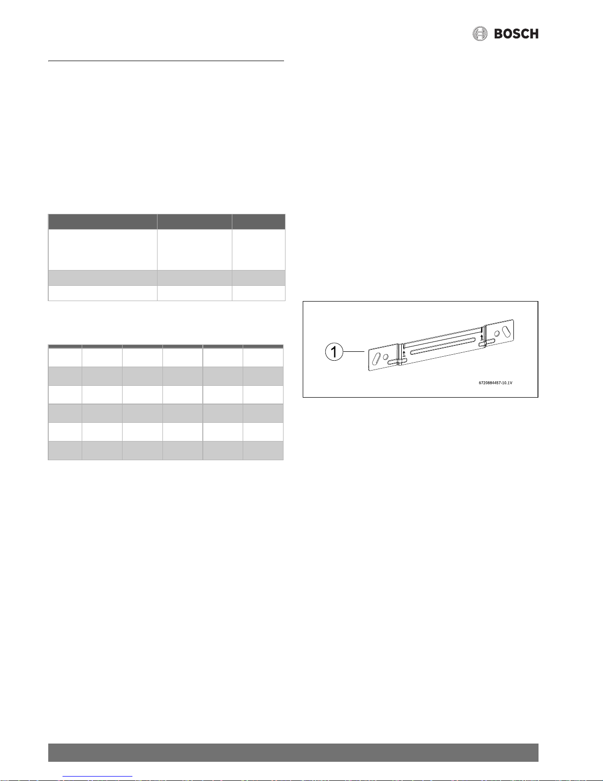
2.5 Accessories (included in the appliance
packaging)
Fig. 1
[1] Bracket
Water characteristics Unit
Water hardness, min. ppm
grain/US gallon
°dH
120
7.2
6.7
pH, min. – max. 6.5 – 9.5
Conductivity, min. – max. μS/cm 130 – 1500
Table 2 Water characteristics
TR 4500 T 30 E B
TR 4500 T 50 E B
TR 4500 T 80 E B
TR 4500 T 100 E B
TR 4500 T 120 E B
TR 4500 T 150 E B
Table 3
 Loading...