


TR5000R
Bosch TR5000R, TR7000R, TR5000R 18/21 EAB, TR7000R 24/27 DESOAB, TR5000R 24/27 EAB Installation Instructions Manual
...
TR5000R | TR7000R
TR5000R 18/21 EAB | TR5000R 24/27 EAB | TR7000R 18/21 DESOAB | TR7000R 24/27 DESOAB
[de] Montageanleitung 2
[en] Installation instructions 6
[fr] Notice de montage 10
[pl] Instrukcja montażu 15
6 720 891 048 (2019/01) DIV

Inhaltsverzeichnis
Inhaltsverzeichnis 1 Sicherheitshinweise
1 Sicherheitshinweise . . . . . . . . . . . . . . . . . . . . . . . . . . . . . . . . . . 2
2 Montageanleitung . . . . . . . . . . . . . . . . . . . . . . . . . . . . . . . . . . . . 3
2.1 Montage . . . . . . . . . . . . . . . . . . . . . . . . . . . . . . . . . . . . . . 3
3 Technische Daten . . . . . . . . . . . . . . . . . . . . . . . . . . . . . . . . . . . . . 5
3.1 Solarbetrieb . . . . . . . . . . . . . . . . . . . . . . . . . . . . . . . . . . . 5
4 Sonderzubehör. . . . . . . . . . . . . . . . . . . . . . . . . . . . . . . . . . . . . . . 5
Dieses Gerät ist nur für den privaten Haushalt und das
häusliche Umfeld bestimmt.
Die Montageanleitung bitte sorgfältig durchlesen,
danach handeln und aufbewahren! Bei Weitergabe
des Gerätes diese Montageanleitung beilegen.
• Das Gerät nur von einem Fachmann anschließen
und in Betrieb nehmen lassen.
• Das Gerät wie in Text und Bild beschrieben montie-
5 Umweltschutz/Entsorgung. . . . . . . . . . . . . . . . . . . . . . . . . . . . . 5
ren und bedienen. Wir übernehmen keine Haftung
für Schäden, die durch Nichtbeachtung dieser Anleitung entstehen.
• Beiliegende Wasseranschlussstutzen unbedingt
verwenden und wie im Beiblatt angegeben montieren. Sicherstellen, dass im Kaltwasserzulauf ein
Rückschlagventil eingebaut wird.
• Dieses Gerät ist für den Gebrauch bis zu einer Höhe
von 2 000 m über dem Meeresspiegel bestimmt.
• Das Gerät nur in einem frostfreien Raum installieren
und lagern (Restwasser).
WARNUNG:
Stromschlaggefahr!
Schalten Sie im Fehlerfall sofort die Netzspannung
ab!
Vor dem Öffnen des Gerätes die Stromzufuhr zum
Gerät unterbrechen.
Bei einer Undichtigkeit am Gerät sofort die Kaltwasserleitung schließen.
Diese Installationsanleitung richtet sich an Fachleute
für Wasserinstallationen, Heizungs- und Elektrotechnik. Die Anweisungen in allen Anleitungen müssen eingehalten werden. Bei Nichtbeachten können
Sachschäden und Personenschäden bis hin zur Lebensgefahr entstehen.
▶ Installationsanleitungen (Wärmeerzeuger, Hei-
zungsregler, usw.) vor der Installation lesen.
▶ Sicherheits- und Warnhinweise beachten (
kapitel 2).
▶ Nationale und regionale Vorschriften, technische
Regeln und Richtlinien beachten.
• Die gesetzlichen Vorschriften des jeweili-gen Landes, des örtlichen Elektrizitäts-Versorgungsunternehmens und des Wasserwerkes müssen
eingehalten werden.
• Der Durchlauferhitzer ist ein Gerät der Schutzklasse I und muss an den Schutzleiter angeschlossen
werden.
2
Product Name – 6 720 891 048 (2019/01)

Montageanleitung
• Vorsicht: Geerdete Wasserleitungen können das
Vorhandensein eines Schutzleiters vortäuschen.
• Das Gerät muss dauerhaft an festverlegte Leitungen
angeschlossen werden. Der Leitungsquerschnitt
muss der zu installierenden Leistung entsprechen.
• Zur Erfüllung der einschlägigen Sicherheitsvorschriften muss installationsseitig eine allpolige
Trennvorrichtung vorhanden sein ( kapitel 3).
Die Kontaktöffnung muss mindestens 3 mm betragen.
• Überprüfen Sie, ob der Wassereingangsdruck, maximum und minimum, mit den Herstelleranforderungen übereinstimmt ( kapitel 3).
• Für die Modelle TR 4000, TR 5000 und TR 5000R
darf der Kaltwasser Zulauf nicht von anderen WarmWasser Systemen erfolgen.
• Für die Modelle TR 6000R, TR 7000R und TR 7000
darf die Zulauftemperatur 55 °C nicht übersteigen.
• Das Gerät ist nur für den geschlossenen (druckfesten) Betrieb geeignet.
• Entsprechend der europäischen Norm EN603352-35:2016 müssen Durchlauferhitzer, die für Duschanwendungen eingesetzt werden, auf 55 °C begrenzt sein.
• Armaturen müssen für den Betrieb mit geschlossenen (druckfesten) Durchlauferhitzern zugelassen
sein.
• Der spezifische Wasserwiderstand darf nicht unter
1 300 Ωcm liegen. Den Wasserwiderstand beim
örtlichen Wasserversorger erfragen.
• Das Gerät ist für den Anschluss an DVGW-geprüfte
Kunststoffrohre geeignet.
• Das elektrische Anschlusskabel vor der Monta-
ge spannungslos machen und die Wasserzuleitung absperren!
• Den Elektroanschluss erst nach dem Wasseranschluss durchführen.
• In der Rückwand nur die Öffnungen herstellen, die
für die Montage benötigt werden. Bei erneuter Montage müssen die unbenutzten Öffnungen wasserdicht verschlossen werden.
• Spannungsführende Teile dürfen nach der Montage
nicht mehr berührbar sein.
• Keine Scheuermittel oder anlösende Reinigungsmittel verwenden.
• Keinen Dampfreiniger benutzen.
Sicherheit elektrischer Geräte für den Hausgebrauch und ähnliche Zwecke
Zur Vermeidung von Gefährdungen durch elektrische
Geräte gelten entsprechend EN 60335-2-35 folgende
Vorgaben:
„Dieses Gerät kann von Kindern ab 3 Jahren und darüber sowie von Personen mit verringerten physischen,
sensorischen oder mentalen Fähigkeiten oder Mangel
an Erfahrung und Wissen benutzt werden, wenn sie
beaufsichtigt oder bezüglich des sicheren Gebrauchs
des Gerätes unterwiesen wurden und die daraus resultierenden Gefahren verstehen. Kinder dürfen nicht mit
dem Gerät spielen. Reinigung und Benutzer-Wartung
dürfen nicht von Kindern ohne Beaufsichtigung durchgeführt werden.“
„Wenn die Netzanschlussleitung beschädigt wird,
muss sie durch den Hersteller oder seinen Kundendienst oder eine ähnlich qualifizierte Person ersetzt
werden, um Gefährdungen zu vermeiden.“
2 Montageanleitung
• Montieren Sie das Gerät wie im Bildteil beschrieben. Beachten Sie die
Hinweise im Text.
2.1 Montage
Auspacken/Haube abnehmen (Bild 1)
• Gerät auspacken und auf Transportschäden kontrollieren. Liegt ein
Schaden vor, Gerät nicht anschließen.
• Lieferumfang kontrollieren: Gerät, Montagesatz mit Beiblatt, Montageanleitung, Gebrauchsanleitung.
• Verpackung und Altgerät umweltgerecht entsorgen.
• Beim Abnehmen der Haube ist durch einen zentralen Verschluss hinter der Serviceklappe fixiert.
Montagevorbereitung (Bild 2)
Wichtig: Nur den beiliegenden Montagesatz verwenden. Die mitgelie-
ferten Wasseranschlussstutzen müssen unbedingt eingebaut werden!
• Wasserzuleitung absperren. Der elektrische Anschluss (Anschlusskabel) muss spannungsfrei sein. Sicherungen herausdrehen oder
ausschalten.
• Die Wasseranschlussstutzen nach der Anleitung auf dem Beiblatt
montieren.
• Die Anschlussleitung kann wahlweise oben (X) oder unten (Y) eingeführt werden.
• Die Rückwand muss an der vorgesehenen Stelle auf dem Kaltwasserstutzen aufliegen (8.).
Wandmontage (Bild 3)
• Die Tülle muss das Anschlusskabel eng umschließen. Wird sie bei
der Montage beschädigt, müssen die Löcher wasserdicht verschlossen werden.
• Die Netzanschlussklemme kann oben (X) oder unten (Y) montiert
werden. Die Ummantelung des Anschlusskabels muss mindestens
40 mm in das Gerät hineinragen.
• Der Wandabstand ist variabel. So können Unebenheiten der Wand
ausgeglichen werden. Bei einem Wandabstand von 8–16 mm
die Distanzhalter einsetzen und die Verlängerung montieren (3.–5.).
• Das Gerät muss fest an der Wand montiert werden. Befestigen Sie es
gegebenenfalls an den unteren Stellschrauben (6.).
6 720 891 048 (2019/01)
3
Montageanleitung
Wasseranschluss (Bild 4, 5)
▶ Vor dem Wasseranschluss das AquaStop Verbindungsrohr in die Tülle
einführen (Bild 5, [7.]). Die Tülle muss das Verbindungsrohr dicht
abschließen.
▶ Den Wasseranschluss vornehmen, anschließend die Kaltwasserzulei-
tung öffnen.
▶ Beim Verschrauben der Anschlüsse darauf achten, dass der AquaS-
top vertikal ausgerichtet ist.
▶ Die Grifflächen zusammendrücken und die Transportsicherung nach
rechts abziehen (Bild 5, [10.])
▶ Das Gerät muss entlüftet werden. Dazu Warmwasserhahn ganz
öffnen und das Gerät 1 Minute lang spülen.
Elektroanschluss/Montage (Bild 6)
Begrenzung der Auslauftemperatur auf 53 °C (Bild 10).
(Nur für die folgenden Geräte: TR 5000, TR7000, TR 5000R, TR 6000R
und TR 7000R.)
WARNUNG:
Stromschlaggefahr!
Wie Sie den Temperaturbegrenzungsschalter positionieren,
▶ Vor dem Öffnen des Gerätes die Stromzufuhr zum Gerät unterbre-
chen.
▶ Entfernen Sie die Gerätehaube.
▶ Bewegen Sie den Temperaturbegrenzungsschalter auf die 53°C posi-
tion ( Bild 10).
• Bei Betrieb mit dem Lastabwurfrelais muss die Regelungselektronik
kodiert werden. Die Kodiernase auf der Elektronik entfernen [4.].
Nur bei Geräten mit Leistungsumschaltung:
▶ Vor Anschluss der Leitungen an die Netzanschlussklemme die Leis-
tung mit dem Leistungsumschalter einstellen: nominale Leistung
links, reduzierte Leistung rechts [1.] und die eingestellte Leistung am
Typenschild markieren.
▶ Die Leitungen an der Netzanschlussklemme festschrauben [2.].
▶ Sicherheitsbegrenzer einschalten [3.].
▶ Haube montieren [4.–7.].
Installationshinweis
• Die Installation nicht-steckerfertiger Geräte ist vom jeweiligen
Netzbetreiber oder von einem eingetragenen Fachbetrieb vorzu-
nehmen, der Ihnen auch bei der Einholung der Zustimmung
des jeweiligen Netzbetreibers für die Installation des Gerätes
behilflich ist.
Inbetriebnahme (Bild 7)
Das Gerät stimmt mit IEC 61000-3-12 überein.
Erstinbetriebnahme
▶ Sicherungen einschalten.
▶ Temperatur einstellen.
▶ Startspülung: Warmwasserhahn ganz öffnen und mindestens
1 Minute lang Wasser beziehen. Aus Sicherheitsgründen beginnt das
Gerät erst danach mit dem Heizen.
Tipp: Startet das Gerät aufgrund von zu geringem Durchfluss nicht, Per-
lator, Brausekopf oder Ähnliches zum Starten entfernen und Vorgang
wiederholen.
• Erklären Sie dem Benutzer die Bedienung des Gerätes.
Zusatzinformationen (Bild 8)
• Erreicht das Gerät aufgrund von zu geringem Wasser-leitungsdruck in
Ihrer Hausinstallation keinen genügen-den Durchfluss, entfernen Sie
den Durchflussbegrenzer [1.–3.].
• Vorrangschaltung für die Kombination mit Elektro-Speicherheizgeräten:
Für den Betrieb mit Vorrangschaltung ist ein spezielles Lastabwurfrelais
BZ 45L21 (Sonderzubehör) erforderlich. Andere, bereits vorhandene
Lastabwurfrelais, ausgenommen elektronische Lastabwurfrelais,
können Fehlfunktionen aufweisen (Schaltplan).
4
6 720 891 048 (2019/01)
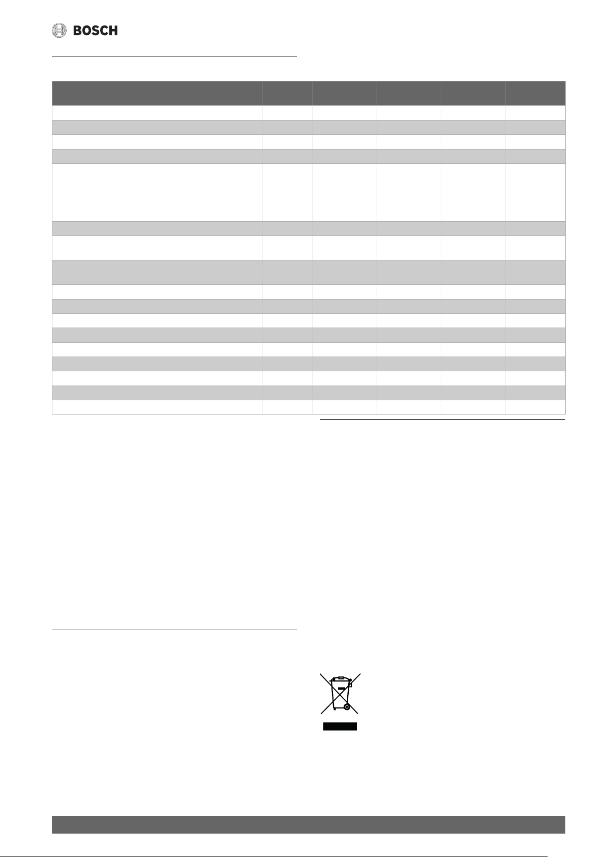
3 Technische Daten
Technische Daten
TR5000R 18/21
EAB
Nennleistung [kW] 15/21 21/27 15/21 21/27
Nennspannung [V] 400 400 400 400
Absicherung [A] 32 40 32 40
Mindestens Leitungsquerschnitt* [mm2] 4 6 4 6
Warmwassermenge bei Nennleistung
bei Temperaturerhöhung von
12 °C auf 38 °C (ohne Durchflussmengenbegrenzer)
12 °C auf 38 °C (mit Durchflussmengenbegrenzer)
12 °C auf 60 °C
Einschaltmenge [l/min] 2,5 2,5 2,5 2,5
Einschaltfließdruck** [MPa (bar)]
Einsatzbereich in Wässern
Spezifischer elektrischer Widerstand bei 15 °C
Nenndruck [MPa (bar)] 1,0 (10) 1,0 (10) 1,0 (10) 1,0 (10)
Maximal zulässige Zulauf-Temperatur [°C] 20 20 55 55
Maximale Netzimpedanz am Anschlussort [Ω] 0,067/0,104 0,067/0,104 0,067/0,104 0,067/0,104
Energieeffizienzklasse A A A A
Lastprofil SSSS
Jahresenergieverbrauch [kWh] 479 479 479 479
Täglicher Stromverbrauch [kWh] 2,203 2,207 2,203 2,207
Schallleistungspegel [dB] 15 15 15 15
Warmwasserbereitungs-Energieeffizienz [%] 38,5 38,5 38,5 38,5
* In Abhängigkeit von der Verlegeart können auch größere Leitungsquer-
schnitte erforderlich sein.
** Hierzu kommt noch der Druckabfall an der Mischbatterie.
3.1 Solarbetrieb
Nur für Geräte, die für Solarbetrieb geeignet sind:
Das Gerät erwärmt bereits vorgewärmtes Wasser auf max.
60 °C. Überschreitet der Kaltwasserzulauf die Temperatur von 55 °C,
wird das Wasser nicht weiter erwärmt.
Wichtig: Die Kaltwasser-Zulauftemperatur darf nicht höher als 55 °C sein!
Wird die Kaltwasser-Zulauftemperatur von 60 °C überschritten, löst das
Gerät eine Sicherheitsabschaltung aus. Deshalb muss in der Hausinstal-
lation ein Thermostatvormischer (z. B. Son-derzubehör BZ 45T20) ein-
gebaut sein, der die Kaltwasser-Zulauftemperatur auf max. 55 °C durch
Zumischung von Kalt-wasser begrenzt.
Abmessungen (Bild 9)
[l/min]
[l/min]
[l/min]
[Ωcm] ≥ 1 300 ≥ 1 300 ≥ 1 300 ≥ 1 300
9,8/11,6
7,6
5,3/6,2
0,04
0,4
Zum Schutz der Umwelt setzen wir unter Berücksichtigung wirtschaftlicher Gesichtspunkte bestmögliche Technik und Materialien ein.
Verpackung
Bei der Verpackung sind wir an den länderspezifischen Verwertungssystemen beteiligt, die ein optimales Recycling gewährleisten.
Alle verwendeten Verpackungsmaterialien sind umweltverträglich und
wiederverwertbar.
Altgerät
Altgeräte enthalten Wertstoffe, die wiederverwertet werden können.
Die Baugruppen sind leicht zu trennen. Kunststoffe sind gekennzeichnet.
Somit können die verschiedenen Baugruppen sortiert und wiederverwertet oder entsorgt werden.
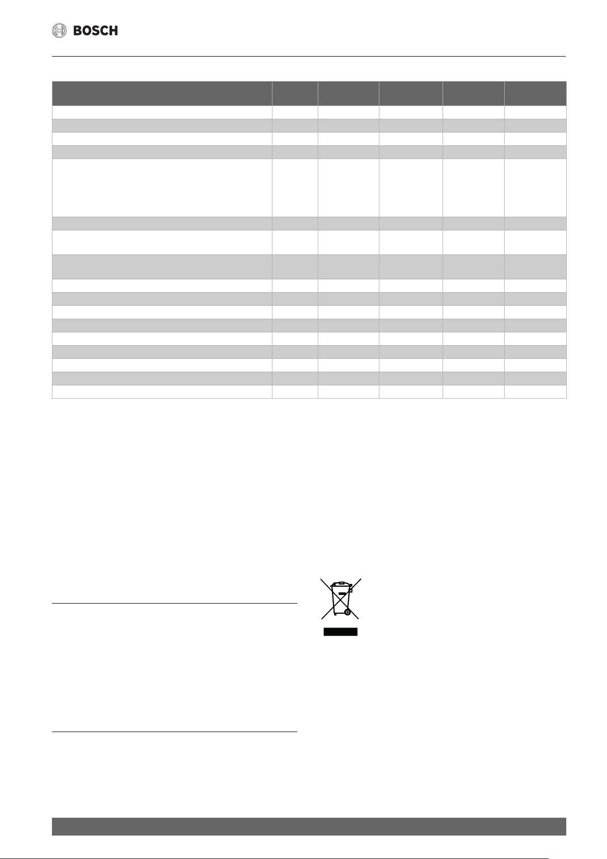
Elektro- und Elektronik-Altgeräte
4 Sonderzubehör
• Rohrbausatz BZ 45U20 zur Verwendung des Gerätes als Untertischgerät
• Vorrangschalter (Lastabwurfrelais) BZ 45L21 für den Betrieb mit
Vorrangschaltung
• Montageset BZ 45K23 für Aufputzinstallation
• Nur für Geräte, die für Solarbetrieb geeignet sind:
Thermostatvormischer BZ 45T20 für den Einbau in die Hausinstallation bei Nutzung von vorgewärmtem Wasser.
Batterien dürfen nicht im Hausmüll entsorgt werden. Verbrauchte Batterien müssen in den örtlichen Sammelsystemen entsorgt werden.
Änderungen vorbehalten.
TR5000R 24/27
EAB
13,0/14,6
9,3
7,1/7,9
0,04
0,4
Nicht mehr gebrauchsfähige Elektro- oder Elektronikgeräte müssen getrennt gesammelt und einer umweltgerechten Verwertung zugeführt werden (Europäische Richtlinie
über Elektro- und Elektronik-Altgeräte).
Nutzen Sie zur Entsorgung von Elektro- oder ElektronikAltgeräten die länderspezifischen Rückgabe- und Sammelsysteme.
TR7000R 18/21
DESOAB
9,8/11,6
7,6
5,3/6,2
0,04
0,4
TR7000R 24/27
DESOAB
13,0/14,6
9,3
7,1/7,9
0,04
0,4
5 Umweltschutz/Entsorgung
Der Umweltschutz ist ein Unternehmensgrundsatz der Bosch-Gruppe.
Qualität der Produkte, Wirtschaftlichkeit und Umweltschutz sind für uns
gleichrangige Ziele. Gesetze und Vorschriften zum Umweltschutz
werden strikt eingehalten.
6 720 891 048 (2019/01)
Änderungen vorbehalten.
5
Table of Contents
Table of Contents 1 Safety information
This appliance is intended for domestic use and the
1 Safety information. . . . . . . . . . . . . . . . . . . . . . . . . . . . . . . . . . . . 6
2 Installation instructions . . . . . . . . . . . . . . . . . . . . . . . . . . . . . . . 7
2.1 Installation . . . . . . . . . . . . . . . . . . . . . . . . . . . . . . . . . . . . 7
3 Technical data. . . . . . . . . . . . . . . . . . . . . . . . . . . . . . . . . . . . . . . . 9
3.1 Solar heated . . . . . . . . . . . . . . . . . . . . . . . . . . . . . . . . . . . 9
household environment only.
Please read this installation instruction manual
carefully, then act accordingly! Store for future
reference. These installation instructions must be
included when transferring this appliance to a new
owner.
4 Special accessories . . . . . . . . . . . . . . . . . . . . . . . . . . . . . . . . . . . 9
5 Environmental protection/disposal. . . . . . . . . . . . . . . . . . . . . . 9
• The appliance may only be connected and put
into operation by a qualified professional.
• Install and operate the appliance as described in
the text and illustrations. We do not accept liability
for damage resulting from failure to heed these
instructions.
• The supplied water connection nozzles must be
used and installed as shown in the supplementary
sheets. Make sure that a check valve is installed in
the cold water supply line.
• This appliance is intended for use up to an altitude
of 2000 m above sea level.
• The appliance may only be installed and stored in a
frost-free room (due to residual water).
WARNING:
Risk of electric shock!
Switch off the mains voltage supply immediately if
a fault occurs.
Disconnect the power supply before opening the
appliance.
Immediately shut off the cold water supply to the
appliance should it leak.
These installation instructions are intended for
plumbers, heating engineers and electricians. All
instructions must be observed. Failure to comply with
instructions may result in material damage and
personal injury, including possible loss of life.
▶ Read the installation instructions (heat source,
heating controller, etc.) before installation (
chapter 2).
▶ Observe the safety instructions and warnings.
▶ Observe national and regional regulations,
technical rules and guidelines.
• The statutory regulations of the respective country,
as well as those of the local electricity and water
suppliers, must be adhered to.
• The continuous-flow heater is a Class I appliance
and must be connected to the protective earth.
6
6 720 891 048 (2019/01)
Installation instructions
• The appliance must be permanently connected to
installed pipes. The conductor cross-section
must comply with the installed appliance power.
CAUTION:
Earthed water pipes may give the appearance of
a connected protective earth.
• To guarantee compliance to relevant safety
regulations, an all-pole separator must be fitted
during installation, according to chapter 3. The
contact opening must be at least 3 mm.
• Ensure that the inlet water pressure, maximum and
minimum, is according with the value specified by
the manufacturer ( chapter 3).
• For TR 5000R the water inlet shall not be connected
to inlet water obtained from any water heating
system.
• For TR 7000R appliances the cold water supply
temperature must not be higher than 55 °C.
• In accordance with EN60335-2-35, when the
appliance is intended to supply water for
showering, the output temperature must be limited
to 55 °C.
• The continuous-flow heater is only suitable for
closed (pressurised) operation.
• The tap and outlet fittings must be approved for
operation with closed (pressurised) continuousflow heater systems.
• The water’s specific electrical resistivity must not
be less than 1 300 Ωcm. Ask the local water utility
company regarding the electrical resistivity of the
water.
• The continuous-flow heater is suitable for
connection to DVGW-tested plastic pipes.
• Disconnect the electrical connection cable from
the supply and shut off the water supply before
connecting the appliance!
• Connect the water supply and then connect the
electrical supply.
• Only make the openings which are required for
installation on the rear of the appliance. If the
appliance is reinstalled, the unused openings must
be provided with watertight sealing.
• Do not touch electrically live parts after installation.
• Do not use aggressive or abrasive cleaning
detergents!
• Do not use a steam cleaner.
Safety of electrical devices for domestic use and
similar purposes
The following requirements apply in accordance with
EN 60335-2-35 in order to prevent hazards from
occurring when using electrical appliances:
“This appliance can be used by children of 3 years and
older, as well as by people with reduced physical,
sensory or mental capabilities or lacking in experience
and knowledge, if they are supervised and have been
given instruction in the safe use of the appliance and
understand the resulting dangers. Children shall not
play with the appliance. Cleaning and user
maintenance must not be performed by children
without supervision.”
“If the power cable is damaged, it must be replaced by
the manufacturer, its customer service department or
a similarly qualified person, so that risks are avoided.”
2 Installation instructions
• Install the appliance as shown in the illustrations. Observe the
instructions in the text.
2.1 Installation
Unpacking/Removing the cover (Fig. 1)
• Unpack the appliance and check for transport damage. If any
components are damaged, then do not connect the appliance.
• Check that your appliance contains all components included in the
scope of delivery: appliance, installation set with supplementary
sheets, installation instructions, operating instructions.
• Please dispose of the packaging and the old appliance in an
environmentally-friendly manner.
• When removing the cover from the appliance, please note the
following:
The cover is fastened by a central closure behind the service flap.
Preparations for installation (Fig. 2)
Important: Only use the supplied installation set.
The supplied water connection nozzles must be installed!
• Shut off water supply. The electrical connection (connection cable)
must be disconnected from the power supply. Unscrew the fuse
or switch off the circuit breaker.
• Install the water connection nozzles according to the instructions
on the supplementary sheet.
• The electrical connection cable can either be guided in at the top (X)
or bottom (Y).
• The rear panel must lie against the cold water connection nozzle
in the position provided for such [8.].
Wall mounting (Fig. 3)
• The grommet must tightly surround the connection cable. If it is
damaged during mounting, the openings must be provided with
watertight sealing.
• The electrical supply terminal can be fitted at the top (X) or
bottom (Y). The sheath of the connection cable must extend for
at least 40 mm into the appliance.
• The distance to the wall is variable. You can compensate for
any unevenness of the wall’s surface. With a distance to the wall of
8–16 mm, insert the spacer and install the extender [3.–5.].
• The appliance must be mounted securely on the wall. If necessary,
attach it at the lower adjustable screws [6.].
6 720 891 048 (2019/01)
7
Installation instructions
Water connection (Fig. 4, 5)
▶ Before connecting the water, guide the AquaStop connection pipe
into the grommet (Fig. 5, [7.]). The grommet must tightly surround
the connection pipe.
▶ Connect the water supply, then open the cold water supply.
▶ When tightening the connections, make sure that the AquaStop is
positioned vertically.
▶ Press the grip surfaces together and pull out the transport protection
attachment to the right (Fig. 5, [10.]).
▶ The appliance must be vented. To do so, open the warm water tap
fully and flush out the appliance thoroughly for 1 minute.
Electrical connection/Mounting (Fig. 6)
Limiting the outlet temperature to 53 °C (Fig. 10).
(Only for the following appliances; TR 5000R and TR 7000R.)
WARNING:
Risk of electric shock!
How to move the temperature limiting switch,
▶ Disconnect the power supply before opening the appliance.
▶ Remove the cover.
▶ Move the temperature limiting switch to the 53°C position (
Fig. 10).
Only for appliances with power selector switches:
▶ Set the power using the power selector switch before connecting the
wires to the mains connection terminal: Nominal output power left,
reduced output right [1.] and the set output marked on the ratings
plate.
▶ Screw the wires tightly into the mains connection terminal [2.].
▶ Switch on the safety limiter [3.].
▶ Install the cover (4.–7.).
Installation note
• The installation of non plug-in ready appliances must be
undertaken by the respective utility operator or by a qualified
specialist company, who can also assist you when you are
requesting the approval of the utility company for installation
of the appliance.
Startup (Fig. 7)
The device is compliant to IEC 61000-3-12.
First start-up
▶ Switch on the fuses
▶ Setting the temperature.
▶ Initial rinsing: Open the warm water tap fully and allow water to flow
for at least 1 minute. Only then (for safety reasons) will the appliance
begin to heat.
Tip: Should the appliance not start because of a reduced flow-rate,
remove the perlator, shower head or similar before start and repeat
the process.
• Explain the operation of the appliance to the user.
Additional information (Fig. 8)
• If the appliance does not have sufficient water flow due to low water
line pressure in your domestic plumbing system, remove the flow-
rate limiter [1.–3.].
• Priority circuit for the combination with electrical storage heaters:
For operation with a priority circuit, a special load shedding relay
BZ 45L21 (special accessory) is required. Other existing load
shedding relays, with the exception of electronic load shedding
relays, may malfunction (Wiring diagram).
• The control electronics must be coded when operated with
a load shedding relay. Remove the keying nose on the electronics
[4.].
8
6 720 891 048 (2019/01)
3 Technical data
Technical data
TR5000R 18/21
EAB
Rated output [kW] 15/21 21/27 15/21 21/27
Rated voltage [V] 400 400 400 400
Fuse protection [A] 32 40 32 40
Minimum conductor cross-section* [mm2] 4 6 4 6
Warm water flow at rated output
with temperature increase from
12 °C to 38 °C (without flow-rate limiter)
12 °C to 38 °C (with flow-rate limiter)
12 °C to 60 °C
Start-up flow [l/min] 2.5 2.5 2.5 2.5
Start-up flow pressure** [MPa (bar)]
Application area in water
specific electric resistance at 15 °C
Rated pressure [MPa (bar)] 1.0 (10) 1.0 (10) 1.0 (10) 1.0 (10)
Maximum permissible supply temperature [°C] 20 20 55 55
Maximum mains impedance at connection point [Ω] 0.067/0.104 0.067/0.104 0.067/0.104 0.067/0.104
Energy efficiency class A A A A
Load profile SSSS
Annual energy consumption [kWh] 479 479 479 479
Daily energy consumption [kWh] 2.203 2.207 2.203 2.207
Sound power level [dB] 15 15 15 15
Hot water heating energy efficiency [%] 38.5 38.5 38.5 38.5
* Larger cable cross-sections may be required depending on the
connection configuration.
** The pressure loss on the mixer must also be added.
3.1 Solar heated
Only for appliances that are suitable for solar heating systems:
The appliance can only heat prewarmed water to a max. of 60 °C.
If the cold water supply exceeds a temperature of 55 °C, the water will
not be warmed any further.
Important: The cold water supply temperature must not be higher
than 55 °C!
If the cold water supply exceeds a temperature of 60 °C, a circuit breaker
will trigger and shut the appliance off. Therefore, the residential
plumbing must be equipped with a thermostatic premixer (e. g. special
accessory BZ 45T20) that will limit the cold water supply temperature
to a max. of 55 °C by appropriately mixing in cold water.
Dimensions (Fig. 9)
4 Special accessories
• Pipe kit BZ 45U20 for use of the appliance as an under-sink
appliance
• Priority switch (load shedding relay) BZ 45L21:
for operation with a priority circuit
• Mounting kit BZ 45K23: for surface mount installation
• Only for appliances that are suitable for solar heating systems:
Thermostatic premixer BZ 45T20: for installation in the domestic
plumbing when using preheated water
[l/min]
[l/min]
[l/min]
[Ωcm] ≥ 1 300 ≥ 1 300 ≥ 1 300 ≥ 1 300
9.8/11.6
7.6
5.3/6.2
0.04
0.4
5 Environmental protection/disposal
Environmental protection is a fundamental corporate strategy of the
Bosch Group.
The quality of our products, their economy and environmental safety are
all of equal importance to us and all environmental protection legislation
and regulations are strictly observed.
We use the best possible technology and materials for protecting the
environment taking account of economic considerations.
Packaging
Where packaging is concerned, we participate in country-specific
recycling processes that ensure optimum recycling.
All of our packaging materials are environmentally compatible and can be
recycled.
Used appliances
Used appliances contain valuable materials that can be recycled.
The various assemblies can be easily dismantled. Synthetic materials are
marked accordingly. Assemblies can therefore be sorted by composition
and passed on for recycling or disposal.
Used electrical and electronic appliances
should use the return and collection systems put in place in the country
concerned.
Batteries must not be disposed together with your household waste.
Used batteries must be disposed of in local collection systems.
TR5000R 24/27
EAB
13.0/14.6
9.3
7.1/7.9
0.04
0.4
Electrical or electronic devices that are no longer
serviceable must be collected separately and sent for
environmentally compatible recycling (in accordance with
the European Waste Electrical and Electronic Equipment
Directive).
To dispose of old electrical or electronic devices, you
TR7000R 18/21
DESOAB
9.8/11.6
7.6
5.3/6.2
0.04
0.4
TR7000R 24/27
DESOAB
13.0/14.6
9.3
7.1/7.9
0.04
0.4
6 720 891 048 (2019/01)
9
 Loading...